2003 MERCEDES-BENZ E320 4MATIC WAGON spare tire
[x] Cancel search: spare tirePage 7 of 354

4 Contents
BRAKE FLUID .............................254
PARKING BRAKE .......................255
ENGINE FAN ...............................255
COOLANT (coolant level) ..........256
COOLANT TEMP. ........................257
LIGHTING SYSTEM ....................258
LIGHT SENSOR ...........................259
REMOVE KEY .............................259
STEERING GEAR OIL .................260
ENGINE OIL LEVEL ................... 261
WASHER FLUID ..........................262
ELEC. STABIL. PROG. (Electronic
stability program) ......................263
TELE AID .....................................263
Practical hintsFirst aid kit .....................................266
Fuses ................................................267
Electrical outlet ..............................269
Hood .................................................270
Checking engine oil level .............273
Automatic transmission fluid
level ............................................. 274Coolant level ....................................274
Adding coolant ........................... 275
Windshield and headlamp washer
system .........................................276
Windshield and headlamp washer
fluid mixing ratio .......................276
Spare wheel, vehicle tools, storage
compartment ............................. 277
Vehicle jack .................................... 278
Wheels ............................................ 279
Tire replacement ....................... 279
Rotating wheels ......................... 280
Spare wheel .................................... 281
Spare wheel bolts ...................... 281
Changing wheels ........................... 282
Tire inflation pressure ................. 287
Battery ............................................. 289
Jump starting ................................. 291
Towing the vehicle ........................ 294
Transmission selector lever,
manually unlocking ................. 296
Exterior lamps ............................... 297
Headlamp assembly .................. 298
Taillamp assemblies .................. 301Changing batteries in the
electronic key ............................304
Synchronizing remote control .306
Emergency engine shut-down .....306
Emergency operation of sliding /
pop-up roof .................................307
Manual release for fuel
filler flap ....................................308
Replacing wiper blade insert .......308
Roof rack ..........................................311
Vehicle careCleaning and care of the vehicle . 314
Power washer .............................. 315
Tar stains ..................................... 315
Paintwork, painted body
components ................................. 315
Engine cleaning .......................... 316
Vehicle washing ......................... 316
Ornamental moldings ................ 316
Headlamps, taillamps, turn signal
lenses ........................................... 316
Cleaning the parktronic system
sensors ......................................... 317
Page 195 of 354
192 Tele Aid
Te ch n i c a l
data Instruments
and controlsOperationDrivingInstrument
cluster displayPractical hints Car care Index
Roadside Assistance button •
Located below the center armrest cover is the Roadside
Assistance button•. Pressing and holding the
button (for longer than 2 seconds) will initiate a call to a
Mercedes-Benz Roadside Assistance dispatcher. The
button will flash while the call is in progress. The
message “ROADSIDE ASSISTANCE – CONNECTING
CALL” will appear in the multifunction display. When
the connection is established, the message “ROADSIDE
ASSISTANCE – CALL CONNECTED” appears in the
multifunction display. The Tele Aid system will transmit
data generating the vehicle identification number,
model, color and location (subject to availability of
cellular and GPS signals).
A voice connection between the Roadside Assistance
dispatcher and the occupants of the vehicle will be
established. When a voice connection is established the
audio system mutes and the message “TELE AID –
ROADSIDE ASSISTANCE CALL ACTIVE” appears in the
multifunction display. The nature of the need for
assistance can then be described. The Mercedes-Benz
Roadside assistance dispatcher will either dispatch a
qualified Mercedes-Benz technician or arrange to tow
your vehicle to the nearest Mercedes-Benz Center. For services such as labor and/or towing charges may
apply. Refer to the Roadside Assistance manual for more
information.
These programs are only available in the USA:
•Sign and Drive services: Services such as jump start,
a few gallons of fuel or the replacement of a flat tire
with the vehicle spare tire are obtainable,
•Remote Vehicle Diagnostics: This function permits
the Mercedes-Benz Roadside Assistance dispatcher
to download malfunction codes and actual vehicle
data.
Notes:
The indicator lamp in the Roadside Assistance
button• remains illuminated in red for approx.
10 seconds during the system self-check after turning
electronic key in steering lock to position 2 (together
with the SOS button and the Information button¡).
See system self-check on page 189 when the indicator
lamp does not light up in red or stays on longer than
approximately 10 seconds.
Page 234 of 354
231 Driving systems
Te ch n i c a l
data Instruments
and controlsOperationDrivingInstrument
cluster displayPractical hints Car care Index Notes:
The malfunction indicator lamp for the ESP is combined
with that of the BAS.
The yellow BAS / ESP malfunction indicator lamp in the
instrument cluster and the yellow ESP warning
lampv in the speedometer dial come on with the
electronic key in steering lock position 2. They should
go out with the engine running.
If the BAS / ESP malfunction indicator lamp comes on
continuously with the engine running, a malfunction
has been detected in either system. Only partial engine
output will be available.
If the BAS malfunctions, the brake system functions in
the usual manner, but without BAS.
If the ESP warning message is displayed, have the BAS
or ESP checked at your authorized Mercedes-Benz
Center as soon as possible.
With the ABS malfunctioning, the ESP is also switched
off.Driving the vehicle with varied size tires will cause the
wheels to rotate at different speeds, therefore the ESP
may activate (yellow ESP warning lamp in speedometer
dial comes on). For this reason, all wheels, including the
spare wheel, must have the same tire size.
When testing the parking brake on a brake test
dynamometer, the engine must be shut off. Otherwise,
the ESP will immediately be engaged and will apply the
rear wheel brakes.
In winter operation, the maximum effectiveness of the
ESP is only achieved with Mercedes-Benz recommended
M+S rated radial-ply tires and / or snow chains.
Synchronizing ESP
If the power supply was interrupted (battery
disconnected or empty), the BAS / ESP malfunction
indicator lamp may be illuminated with the engine
running.
Turn steering wheel completely to the left and then to
the right. The BAS / ESP malfunction indicator lamp
should go out.
Page 268 of 354
265 Contents – Practical hints
Te ch n i c a l
data Instruments
and controlsOperation DrivingInstrument
cluster displayPractical hintsCar care Index
Practical hintsFirst aid kit .....................................266
Fuses ................................................267
Electrical outlet ..............................269
Hood .................................................270
Checking engine oil level .............273
Automatic transmission fluid
level ............................................. 274
Coolant level ................................... 274
Adding coolant ...........................275
Windshield and headlamp washer
system ......................................... 276
Windshield and headlamp washer
fluid mixing ratio ....................... 276Spare wheel, vehicle tools, storage
compartment ............................. 277
Vehicle jack .................................... 278
Wheels ............................................ 279
Tire replacement ....................... 279
Rotating wheels ......................... 280
Spare wheel .................................... 281
Spare wheel bolts ...................... 281
Changing wheels ........................... 282
Tire inflation pressure ................. 287
Battery ............................................. 289
Jump starting ................................. 291
Towing the vehicle ........................ 294
Transmission selector lever,
manually unlocking ................. 296Exterior lamps ................................297
Headlamp assembly ...................298
Taillamp assemblies .................. 301
Changing batteries in the
electronic key ............................304
Synchronizing remote control .306
Emergency engine shut-down .....306
Emergency operation of sliding /
pop-up roof .................................307
Manual release for fuel
filler flap ....................................308
Replacing wiper blade insert .......308
Roof rack ..........................................311
Page 282 of 354
279 Tires, Wheels
Te ch n i c a l
data Instruments
and controlsOperation DrivingInstrument
cluster displayPractical hintsCar care Index Wheels
Replace rims or tires with the same designation,
manufacturer and type as shown on the original part.
See your authorized Mercedes-Benz Center for further
information.
See your authorized Mercedes-Benz Center for
information on tested and recommended rims and tires
for summer and winter operation. They can also offer
advice concerning tire service and purchase.
Tire replacement
Front tires should be replaced in sets. Rims and tires
must be of the correct size and type. For dimensions,
see page 326.
We recommend that you break in new tires for
approximately 60 miles (100 km) at moderate speed.
It is imperative that the wheel mounting bolts be
fastened to a tightening torque of 80 ft.lb. (110 Nm)
whenever wheels are mounted.
For rim and tire specifications, see page 326.
Wa r n i n g !
Worn, old tires can cause accidents. If the tire tread
is badly worn, or if the tires have sustained
damage, replace them.Tires and spare wheel should be replaced after six
years, independently of the remaining tread.When replacing rims, use only genuine
Mercedes-Benz wheel bolts specified for the
particular rim type. Failure to do so can result in
the bolts loosening and possibly an accident.
Page 284 of 354
281 Tires, Wheels
Te ch n i c a l
data Instruments
and controlsOperation DrivingInstrument
cluster displayPractical hintsCar care Index Spare wheel
Important!
Unidirectional tires must always be mounted with arrow
on tire sidewall pointing in direction of vehicle forward
movement.
If the arrow on tire side wall does not point in direction
of vehicle forward movement when using the spare
wheel, observe the following restrictions:
•Drive to the nearest tire repair facility as soon as
possible.
For rim and tire specifications, see page 326.
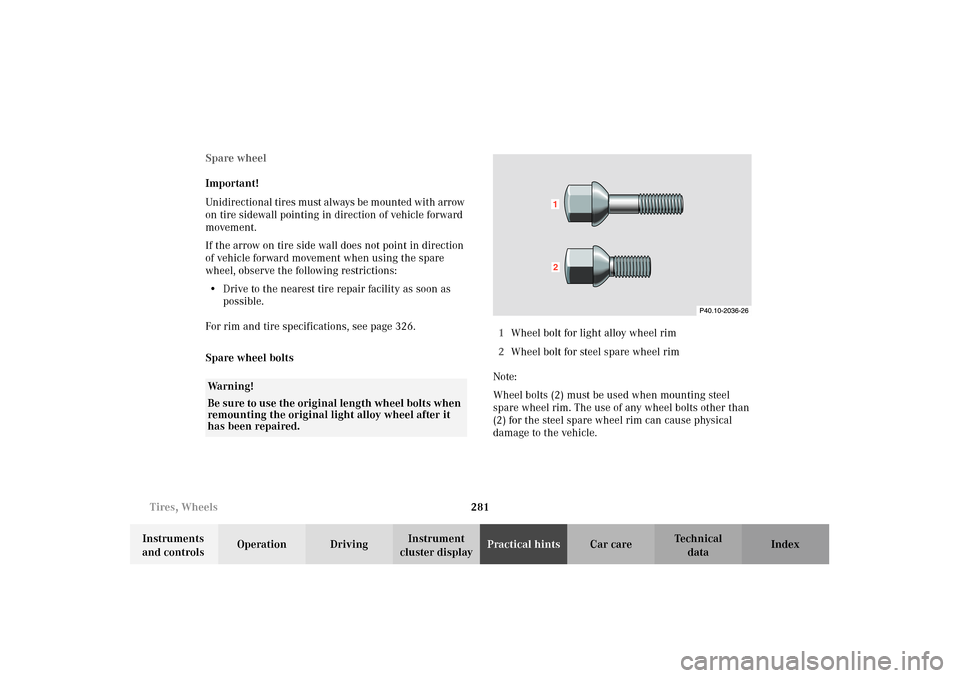
Spare wheel bolts1Wheel bolt for light alloy wheel rim
2Wheel bolt for steel spare wheel rim
Note:
Wheel bolts (2) must be used when mounting steel
spare wheel rim. The use of any wheel bolts other than
(2) for the steel spare wheel rim can cause physical
damage to the vehicle.
Wa r n i n g !
Be sure to use the original length wheel bolts when
remounting the original light alloy wheel after it
has been repaired.
12
Page 288 of 354
285 Tires, Wheels
Te ch n i c a l
data Instruments
and controlsOperation DrivingInstrument
cluster displayPractical hintsCar care Index Important!
When installing steel spare wheel rim, make certain to
use the correct wheel bolts, supplied in the vehicle tool
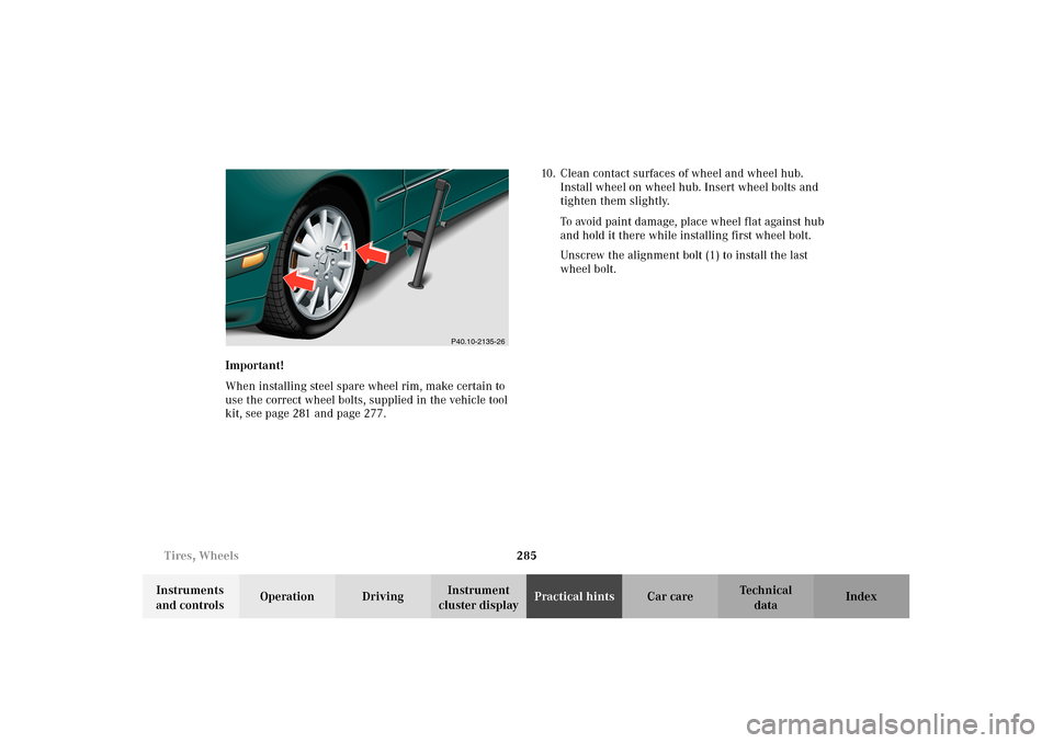
kit, see page 281 and page 277.10. Clean contact surfaces of wheel and wheel hub.
Install wheel on wheel hub. Insert wheel bolts and
tighten them slightly.
To avoid paint damage, place wheel flat against hub
and hold it there while installing first wheel bolt.
Unscrew the alignment bolt (1) to install the last
wheel bolt.
P40.10-2135-26
1
Page 290 of 354
287 Tires, Wheels
Te ch n i c a l
data Instruments
and controlsOperation DrivingInstrument
cluster displayPractical hintsCar care Index Tire inflation pressure
A table (see fuel filler flap) lists the tire inflation
pressures specified for Mercedes-Benz recommended
tires as well as for the varying operating conditions.
Important!
Tire pressure changes by approximately 1.5 psi (0.1 bar)
per 18
°F (10
°C) of air temperature change. Keep this in
mind when checking tire pressure inside a garage -
especially in the winter.
Example:
If garage temperature = approximately +68
°F (+20
°C)
and ambient temperature = approximately +32
°F (0
°C)
then the adjusted air pressure = specified air pressure
+3 psi (+0.2 bar).The pressures listed for light loads are minimum values
offering high driving comfort.
Increased inflation pressures listed for heavier loads
may also be used for light loads. These higher pressures
produce favorable handling characteristics. The ride of
the vehicle, however, will be somewhat harder. Never
exceed the max. values or inflate tires below the min.
values listed in the fuel filler flap.
Tire temperature and pressure increase with the vehicle
speed. Tire pressure should therefore only be checked
and corrected on cold tires. Correct tire pressure in
warm tires only if pressure has dropped below the
pressure listed in the table and the respective operating
conditions are taken into consideration.
An underinflated tire due to a slow leak (e.g. due to a
nail in the tire) may cause damage such as tread
separation, bulging etc.. Regular tire pressure checks
(including the spare tire) at intervals of no more than
14 days are therefore essential.