2003 MERCEDES-BENZ E320 4MATIC WAGON fuel
[x] Cancel search: fuelPage 243 of 354
240 What you should know at the gas station
Te ch n i c a l
data Instruments
and controlsOperationDrivingInstrument
cluster displayPractical hints Car care Index
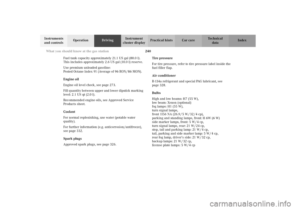
Fuel tank capacity approximately 21.1 US gal (80.0 l).
This includes approximately 2.6 US gal (10.0 l) reserve.
Use premium unleaded gasoline:
Posted Octane Index 91 (Average of 96 RON / 86 MON).
Engine oil
Engine oil level check, see page 273.
Fill quantity between upper and lower dipstick marking
level: 2.1 US qt (2.0 l).
Recommended engine oils, see Approved Service
Products sheet.
Coolant
For normal replenishing, use water (potable water
quality).
For further information (e.g. anticorrosion /antifreeze),
see page 332.
Spark plugs
Approved spark plugs, see page 326.Tire pressure
For tire pressure, refer to tire pressure label inside the
fuel filler flap.
Air conditioner
R-134a refrigerant and special PAG lubricant, see
page 328.
Bulbs
High and low beams: H7 (55 W),
low beam: Xenon (optional)
fog lamps: H1 (55 W),
turn signal lamps,
front 1156 NA (26.9 / 5 W / 32 / 4 cp),
parking and standing lamps, front: H 6W (6 W)
side marker lamps, front: 5 W / 4 cp,
turn signal lamps, rear: 21 W / 24 cp,
stop, tail and parking lamp: 21 W / 4 cp,
tail, parking and side marker lamp: 5 W / 4 cp,
rear fog lamp, driver’s side: 21 W / 32 cp,
backup lamps: 21 W / 32 cp,
license plate lamps: 5 W / 4 cp
Page 246 of 354

243 Contents – Instrument cluster display
Te ch n i c a l
data Instruments
and controlsOperation DrivingInstrument
cluster displayPractical hints Car care Index
Instrument cluster displayMalfunction and indicator lamps in
the instrument cluster .............244
On-board diagnostic system .....244
Check engine malfunction
indicator lamp .............................244
Brake warning lamp ..................245
Supplemental restraint system
(SRS) indicator lamp ..................246
Fuel reserve and fuel cap
placement warning ....................246
Electronic stability program (ESP)
— warning lamp ..........................247
BAS / ESP malfunction indicator
lamp ..............................................247ABS malfunction
indicator lamp ............................ 248
Seat belt warning lamp ............. 248
Malfunction and indicator lamp in
the center console .................... 249
AIRBAG OFF indicator lamp .... 249
Malfunction and warning
messages in the multifunction
display ........................................ 250
DISPLAY DEFECTIVE................ 251
BATTERY / ALTERNATOR ........ 252
ABS-SYSTEM .............................. 253
BRAKE ASSIST........................... 253
BRAKE LINING WEAR .............. 254
BRAKE FLUID ............................ 254PARKING BRAKE .......................255
ENGINE FAN ...............................255
COOLANT (coolant level) ..........256
COOLANT TEMP. ........................257
LIGHTING SYSTEM ....................258
LIGHT SENSOR ...........................259
REMOVE KEY .............................259
STEERING GEAR OIL................. 260
ENGINE OIL LEVEL ................... 261
WASHER FLUID .........................262
ELEC. STABIL. PROG. (Electronic
stability program) ......................263
TELE AID ..................................... 263
Page 247 of 354
244 Malfunction and indicator lamps
Te ch n i c a l
data Instruments
and controlsOperation DrivingInstrument
cluster displayPractical hints Car care Index
Malfunction and indicator lamps
in the instrument cluster
General information:
If a bulb in the instrument cluster fails to light up
during the bulb self-check when turning the electronic
key in steering lock to position 2, have it checked and
replaced if necessary.
On-board diagnostic system
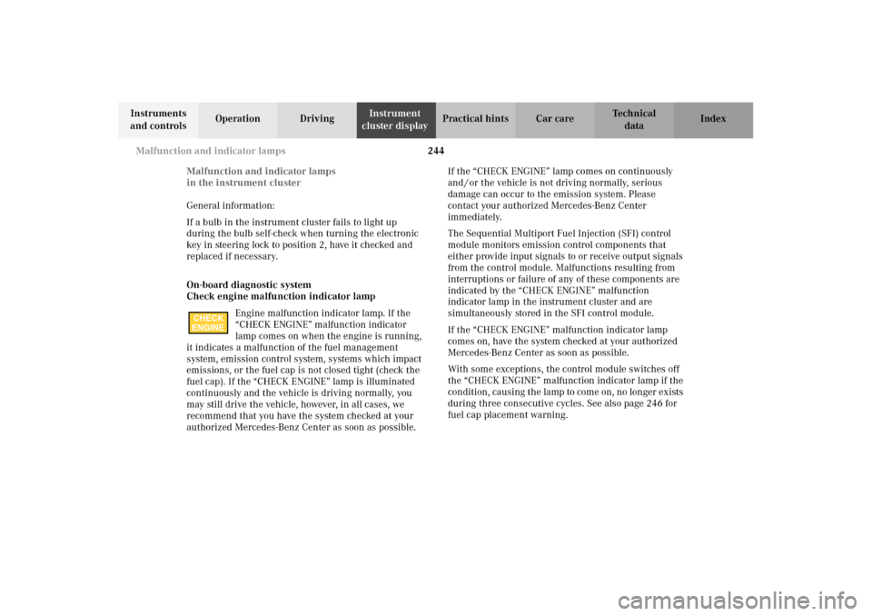
Check engine malfunction indicator lamp
Engine malfunction indicator lamp. If the
“CHECK ENGINE” malfunction indicator
lamp comes on when the engine is running,
it indicates a malfunction of the fuel management
system, emission control system, systems which impact
emissions, or the fuel cap is not closed tight (check the
fuel cap). If the “CHECK ENGINE” lamp is illuminated
continuously and the vehicle is driving normally, you
may still drive the vehicle, however, in all cases, we
recommend that you have the system checked at your
authorized Mercedes-Benz Center as soon as possible. If the “CHECK ENGINE” lamp comes on continuously
and / or the vehicle is not driving normally, serious
damage can occur to the emission system. Please
contact your authorized Mercedes-Benz Center
immediately.
The Sequential Multiport Fuel Injection (SFI) control
module monitors emission control components that
either provide input signals to or receive output signals
from the control module. Malfunctions resulting from
interruptions or failure of any of these components are
indicated by the “CHECK ENGINE” malfunction
indicator lamp in the instrument cluster and are
simultaneously stored in the SFI control module.
If the “CHECK ENGINE” malfunction indicator lamp
comes on, have the system checked at your authorized
Mercedes-Benz Center as soon as possible.
With some exceptions, the control module switches off
the “CHECK ENGINE” malfunction indicator lamp if the
condition, causing the lamp to come on, no longer exists
during three consecutive cycles. See also page 246 for
fuel cap placement warning.
CHECK
ENGINE
Page 249 of 354
246 Malfunction and indicator lamps
Te ch n i c a l
data Instruments
and controlsOperation DrivingInstrument
cluster displayPractical hints Car care Index
Supplemental restraint system (SRS) indicator lamp
The operational readiness of the airbag
system is verified by the indicator lamp SRS
in the instrument cluster when turning the
electronic key in steering lock to position 1 or 2. If no
malfunction is detected, the lamp will go out after
approximately 4 seconds; after the lamp goes out, the
system continues to monitor the components and
circuitry of the airbag system and will indicate a
malfunction by coming on again.
See page 68 for notes on airbags, see page 67 for belt
tensioners and page 57 for infant and child seat
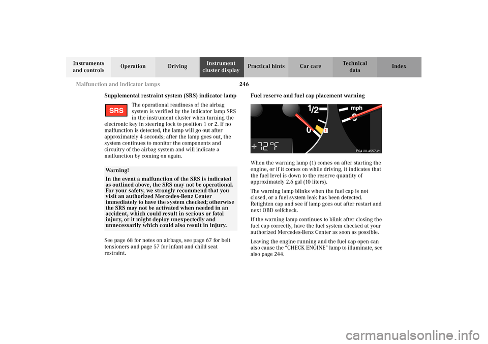
restraint.Fuel reserve and fuel cap placement warning
When the warning lamp (1) comes on after starting the
engine, or if it comes on while driving, it indicates that
the fuel level is down to the reserve quantity of
approximately 2.6 gal (10 liters).
The warning lamp blinks when the fuel cap is not
closed, or a fuel system leak has been detected.
Retighten cap and see if lamp goes out after restart and
next OBD selfcheck.
If the warning lamp continues to blink after closing the
fuel cap correctly, have the fuel system checked at your
authorized Mercedes-Benz Center as soon as possible.
Leaving the engine running and the fuel cap open can
also cause the “CHECK ENGINE” lamp to illuminate, see
also page 244.
Wa r n i n g !
In the event a malfunction of the SRS is indicated
as outlined above, the SRS may not be operational.
For your safety, we strongly recommend that you
visit an authorized Mercedes-Benz Center
immediately to have the system checked; otherwise
the SRS may not be activated when needed in an
accident, which could result in serious or fatal
injury, or it might deploy unexpectedly and
unnecessarily which could also result in injury.SRS
1
P54.30-4557-21
Page 268 of 354
265 Contents – Practical hints
Te ch n i c a l
data Instruments
and controlsOperation DrivingInstrument
cluster displayPractical hintsCar care Index
Practical hintsFirst aid kit .....................................266
Fuses ................................................267
Electrical outlet ..............................269
Hood .................................................270
Checking engine oil level .............273
Automatic transmission fluid
level ............................................. 274
Coolant level ................................... 274
Adding coolant ...........................275
Windshield and headlamp washer
system ......................................... 276
Windshield and headlamp washer
fluid mixing ratio ....................... 276Spare wheel, vehicle tools, storage
compartment ............................. 277
Vehicle jack .................................... 278
Wheels ............................................ 279
Tire replacement ....................... 279
Rotating wheels ......................... 280
Spare wheel .................................... 281
Spare wheel bolts ...................... 281
Changing wheels ........................... 282
Tire inflation pressure ................. 287
Battery ............................................. 289
Jump starting ................................. 291
Towing the vehicle ........................ 294
Transmission selector lever,
manually unlocking ................. 296Exterior lamps ................................297
Headlamp assembly ...................298
Taillamp assemblies .................. 301
Changing batteries in the
electronic key ............................304
Synchronizing remote control .306
Emergency engine shut-down .....306
Emergency operation of sliding /
pop-up roof .................................307
Manual release for fuel
filler flap ....................................308
Replacing wiper blade insert .......308
Roof rack ..........................................311
Page 290 of 354
287 Tires, Wheels
Te ch n i c a l
data Instruments
and controlsOperation DrivingInstrument
cluster displayPractical hintsCar care Index Tire inflation pressure
A table (see fuel filler flap) lists the tire inflation
pressures specified for Mercedes-Benz recommended
tires as well as for the varying operating conditions.
Important!
Tire pressure changes by approximately 1.5 psi (0.1 bar)
per 18
°F (10
°C) of air temperature change. Keep this in
mind when checking tire pressure inside a garage -
especially in the winter.
Example:
If garage temperature = approximately +68
°F (+20
°C)
and ambient temperature = approximately +32
°F (0
°C)
then the adjusted air pressure = specified air pressure
+3 psi (+0.2 bar).The pressures listed for light loads are minimum values
offering high driving comfort.
Increased inflation pressures listed for heavier loads
may also be used for light loads. These higher pressures
produce favorable handling characteristics. The ride of
the vehicle, however, will be somewhat harder. Never
exceed the max. values or inflate tires below the min.
values listed in the fuel filler flap.
Tire temperature and pressure increase with the vehicle
speed. Tire pressure should therefore only be checked
and corrected on cold tires. Correct tire pressure in
warm tires only if pressure has dropped below the
pressure listed in the table and the respective operating
conditions are taken into consideration.
An underinflated tire due to a slow leak (e.g. due to a
nail in the tire) may cause damage such as tread
separation, bulging etc.. Regular tire pressure checks
(including the spare tire) at intervals of no more than
14 days are therefore essential.
Page 291 of 354
288 Tires, Wheels
Te ch n i c a l
data Instruments
and controlsOperation DrivingInstrument
cluster displayPractical hintsCar care Index
If a tire constantly loses air, it should be inspected for
damage.
The spare tire should be checked periodically for
condition and inflation. Spare tire will age and become
worn over time even if never used, and thus should be
inspected and replaced when necessary.
Wa r n i n g !
Follow recommended inflation pressures.
Do not overinflate tires. Overinflated tires can
result in sudden deflation (blowout) because they
are more likely to become punctured or damaged
by road debris, potholes etc.
Do not underinflate tires. Underinflated tires wear
unevenly, adversely affect handling and fuel
economy, and are more likely to fail from being
overheated.Do not overload the tires by exceeding the specified
vehicle capacity weight (as indicated by the label
on the driver’s door latch post). Overloading the
tires can overheat them, possibly causing a
blowout.
Page 296 of 354
293 Jump starting
Te ch n i c a l
data Instruments
and controlsOperation DrivingInstrument
cluster displayPractical hintsCar care Index 4. Clamp one end of the second jumper cable to the
grounded negative (–) terminal of the charged
battery and the final connection to the negative (–)
under hood terminal (3) of the disabled vehicle.
Important!
5. Start engine of the vehicle with the charged battery
and run at high idle. Make sure the cables are not
on or near pulleys, fans, or other parts that move
when the engine is started. Allow the discharged
battery to charge for a few minutes. Start engine of
the disabled vehicle in the usual manner.6. After the engine has started, remove jumper cables
by exactly reversing the above installation
sequence, starting with the last connection made
first. When removing each clamp, make sure that it
does not touch any other metal while the other end
is still attached to a battery.
Note:
If engine does not run after several unsuccessful
starting attempts, have it checked at the nearest
authorized Mercedes-Benz Center.
Excessive unburned fuel generated by repeated failed
starting attempts may damage the catalytic converter.