2003 MERCEDES-BENZ CLK-CLASS lights
[x] Cancel search: lightsPage 30 of 330

27 Central locking system
Technical
data Instruments
and controlsOperationDrivingInstrument
cluster displayPractical hints Car care Index Central locking system
Radio frequency and infrared remote control
The electronic key has an integrated radio frequency
and infrared remote control.
Due to the extended operational range of the remote
control, it could be possible to unintentionally lock or
unlock the vehicle by pressing the transmit button. If
one of the transmit buttons is pressed, the battery check
lamp lights up briefly – indicating that the batteries are
in order. See page 283 for checking batteries.
The vehicle doors, trunk and fuel filler flap can be
centrally locked and unlocked via remote control.
Opening and closing the windows and sliding/pop-up
roof remotely can only be done with the infrared portion
of the remote control. Aim transmitter eye at a
receiver (6 or 7), press and hold transmit button Œ
or ‹.
With vehicle centrally locked, the trunk can also be
opened by using the remote control.
If the electronic key is inserted in steering lock, the
vehicle cannot be locked or unlocked, and the trunk lid
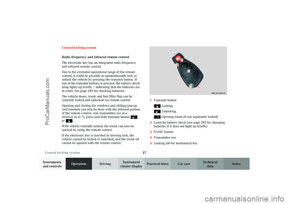
cannot be opened with the remote control.1Transmit button
‹ Locking
ΠUnlocking
Š Opening trunk (if not separately locked)
2Lamp for battery check (see page 283 for changing
batteries if it does not light up briefly)
3PANIC button
4Transmitter eye
5Locking tab for mechanical key
P80.35-2032-26
24
3
5
1
J_C208_II.book Seite 27 Donnerstag, 31. Mai 2001 10:13 10
ProCarManuals.com
Page 59 of 330

56 Seats
Technical
data Instruments
and controlsOperationDrivingInstrument
cluster displayPractical hints Car care Index
Heated seats (front)
(optional on model CLK 430)
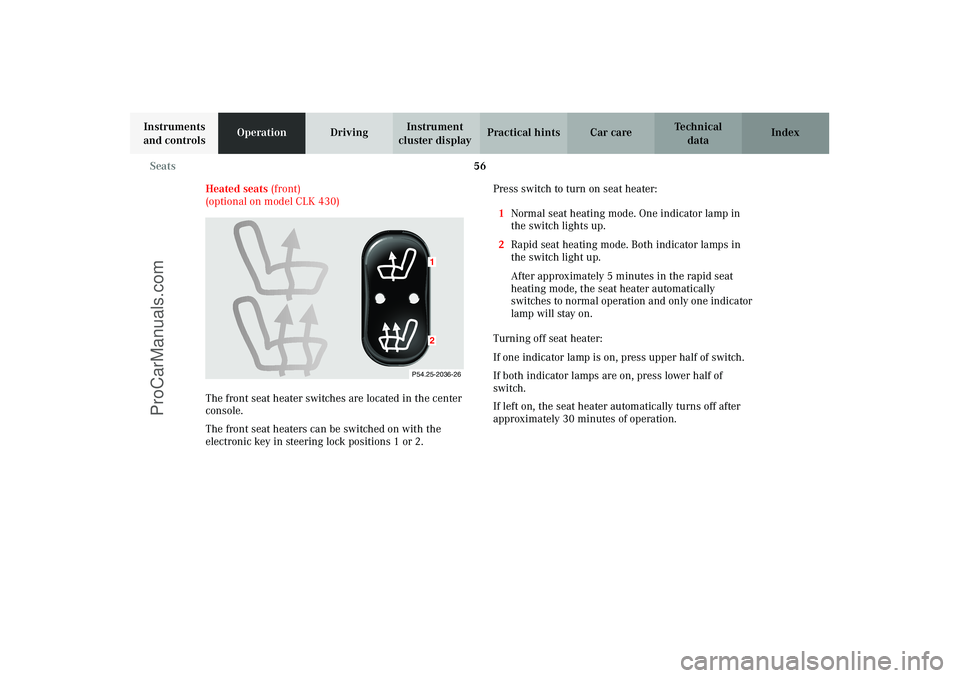
The front seat heater switches are located in the center
console.
The front seat heaters can be switched on with the
electronic key in steering lock positions 1 or 2.Press switch to turn on seat heater:
1Normal seat heating mode. One indicator lamp in
the switch lights up.
2Rapid seat heating mode. Both indicator lamps in
the switch light up.
After approximately 5 minutes in the rapid seat
heating mode, the seat heater automatically
switches to normal operation and only one indicator
lamp will stay on.
Turning off seat heater:
If one indicator lamp is on, press upper half of switch.
If both indicator lamps are on, press lower half of
switch.
If left on, the seat heater automatically turns off after
approximately 30 minutes of operation.
P54.25-2036-26
12
J_C208_II.book Seite 56 Donnerstag, 31. Mai 2001 10:13 10
ProCarManuals.com
Page 120 of 330

117 Exterior lamp switch
Technical
data Instruments
and controlsOperationDrivingInstrument
cluster displayPractical hints Car care Index Notes:
With the electronic key removed and the driver’s door
open, a warning sounds and the message “SWITCH OFF
LIGHTS” in the multifunction indicator appears if the
vehicle’s exterior lamps (except standing lamps) are not
switched off.
Fog lamps will operate with the parking lamps and / or
the low beam headlamps on. Fog lamps should only be
used in conjunction with low beam headlamps. Consult
your State or Province Motor Vehicle Regulations
regarding allowable lamp operation.
Fog lamps are automatically switched off when the
exterior lamp switch is turned to position D.Daytime running lamps (Canada only)
When the engine is running and the selector lever is in
a driving position, the low beam headlamps (includes
parking lamps, side marker lamps, taillamps and
license plate lamps) are automatically switched on.
When shifting from a driving position to position “N”
or “P”, the low beam switches off (2 seconds delay).
For nighttime driving the exterior lamp switch should
be turned to position B to permit activation of the
high beam headlamps.
Night security illumination
When exiting the vehicle after driving with the exterior
lamps on, they switch on again for added illumination
for approximately 30 seconds after closing the last door.
The lamp-on time period can be changed at your
Mercedes-Benz Center.
J_C208_II.book Seite 117 Donnerstag, 31. Mai 2001 10:13 10
ProCarManuals.com
Page 198 of 330

195 Automatic transmission
Technical
data Instruments
and controlsOperationDrivingInstrument
cluster displayPractical hints Car care Index Stopping
For brief stops, e.g. at traffic lights, leave the
transmission in gear and hold vehicle with the service
brake.
For longer stops with the engine idling, shift into “N”
or “P” and hold the vehicle with the service brake.
When stopping the vehicle on an uphill gradient, do not
hold it with the accelerator, use the brake. This avoids
unnecessary transmission heat build up.
Maneuvering
To maneuver in tight areas, e.g. when pulling into a
parking space, control the vehicle speed by gradually
releasing the brakes. Accelerate gently and never
abruptly step on the accelerator.
To rock a vehicle out of soft ground (mud or snow),
alternately shift from forward to reverse, while applying
slight partial throttle.Rocking a vehicle free in this manner may cause the
ABS or traction system malfunction indicator lamp to
come on. Turn off and restart the engine to clear the
malfunction indication.
Wa r n i n g !
Getting out of your vehicle with the selector lever
not fully engaged in position “P” is dangerous.
Also, when parked on an incline, position “P” alone
may not prevent your vehicle from moving,
possibly hitting people or objects.Always set the parking brake in addition to shifting
to position “P”, see page 202 for parking brake. When parked on an incline, also turn front wheel
against curb.Wa r n i n g !
When leaving the vehicle, always remove the
electronic key from the steering lock, and lock the
vehicle. Do not leave children unattended in the
vehicle, or with access to an unlocked vehicle.
Children could move the gear selector lever from
position “P”, which could result in an accident or
serious personal injury.
J_C208_II.book Seite 195 Donnerstag, 31. Mai 2001 10:13 10
ProCarManuals.com
Page 232 of 330

229 Malfunction and indicator lamps
Technical
data Instruments
and controlsOperation DrivingInstrument
cluster displayPractical hints Car care Index Electronic stability program (ESP) — warning lamp
The yellow ESP warning lamp in the
speedometer dial comes on with the
electronic key in steering lock position 2.
It should go out with engine running.
See page 218 if the warning lamp lights up or flashes
when the vehicle is moving.
BAS / ESP malfunction indicator lamp
The malfunction indicator lamp for the ESP
is combined with that of the BAS.
The yellow BAS/ESP malfunction indicator
lamp in the instrument cluster comes on with the
electronic key in steering lock position 2. It should go
out with the engine running.
If the BAS/ESP malfunction indicator lamp remains
illuminated with the engine running, see page 214 for
notes on the brake assist (BAS) and page 218 for notes
on the electronic stability program (ESP).ABS malfunction indicator lamp
The ABS malfunction indicator lamp in the
instrument cluster comes on with the
electronic key in steering lock position 2 and
should go out with the engine running.
When the ABS malfunction indicator lamp and the
malfunction message in the instrument cluster remains
illuminated while the engine is running, it indicates
that the ABS has detected a malfunction and has
switched off. In this case, the brake system functions in
the usual manner, but without antilock assistance.
With the ABS malfunctioning, the BAS and ESP are also
switched off. Both malfunction indicator lamps and the
ABS malfunction message in the multifunction display
come on with the engine running.
If the charging voltage falls below 10 volts, the
malfunction indicator lamp comes on and the ABS is
switched off. When the voltage is above this value again,
the malfunction indicator lamp should go out and the
ABS is operational.
Have the system checked at your authorized
Mercedes-Benz Center as soon as possible.
See page 216 for notes on the antilock brake system
(ABS).
BAS
ESP
ABS
J_C208_II.book Seite 229 Donnerstag, 31. Mai 2001 10:13 10
ProCarManuals.com
Page 235 of 330

232 Malfunction and warning messages
Technical
data Instruments
and controlsOperation DrivingInstrument
cluster displayPractical hints Car care Index
Malfunction and warning messages in the
multifunction display
Malfunction and warning messages for the following
systems will be displayed immediately in the
multifunction display.
These messages can be cleared from the instrument
cluster by:
•using the J button on the instrument cluster, or
•pressing buttonj, k, è or ÿ on the
multifunction steering wheel.
They are then stored in the malfunction message
memory. See page 106.Notes:
Certain malfunction and warning messages are
accompanied by an audible signal.
Malfunction and warning messages in red are always
accompanied by an audible signal.
Temporary messages such as “SWITCH OFF LIGHTS”
will not be stored in the malfunction message memory.
Wa r n i n g !
All messages contain important information which
should be taken note of and, where malfunction
indicated, addressed as soon as possible at an
authorized Mercedes-Benz Center.Failure to repair condition noted may cause
damage not covered by the Mercedes-Benz Limited
Warranty, or result in property damage or personal
injury.
J_C208_II.book Seite 232 Donnerstag, 31. Mai 2001 10:13 10
ProCarManuals.com
Page 244 of 330

241 Malfunction and warning messages
Technical
data Instruments
and controlsOperation DrivingInstrument
cluster displayPractical hints Car care Index LIGHT SENSOR
With the electronic key removed and the driver’s door
open, a warning sounds and the message “SWITCH OFF
LIGHTS!” appears in the multifunction indicator if the
vehicle’s exterior lamps (except standing lamps) are not
switched off.STEER. WHEEL ADJUST.
For locking the adjustable telescoping steering column,
see page 79.
Line 1 Line 2
STEER. WHEEL ADJUST.
J_C208_II.book Seite 241 Donnerstag, 31. Mai 2001 10:13 10
ProCarManuals.com
Page 274 of 330

271 Jump starting
Technical
data Instruments
and controlsOperation DrivingInstrument
cluster displayPractical hintsCar care Index Proceed as follows:
1. Position the vehicle with the charged battery so that
the jumper cables will reach, but never let the
vehicles touch. Make sure the jumper cables do not
have loose or missing insulation.
2. On both vehicles:
•Turn off engine and all lights and accessories,
except hazard warning flashers or work lights.
•Apply parking brake and shift selector lever to
position “P”.
Important!
3. Clamp one end of the first jumper cable to the
positive (+) under hood terminal of the discharged
battery and the other end to the positive (+) terminal
of the charged battery. Make sure the cable clamps
do not touch any other metal parts.
4. Clamp one end of the second jumper cable to the
grounded negative (–) terminal of the charged
battery and the final connection to the negative (–)
terminal (2) of the discharged battery.Important!
5. Start engine of the vehicle with the charged battery
and run at high idle. Make sure the cables are not
on or near pulleys, fans, or other parts that move
when the engine is started. Allow the discharged
battery to charge for a few minutes. Start engine of
the disabled vehicle in the usual manner.
6. After the engine has started, remove jumper cables
by exactly reversing the above installation
sequence, starting with the last connection made
first. When removing each clamp, make sure that it
does not touch any other metal while the other end
is still attached.
Notes:
If engine does not run after several unsuccessful
starting attempts, have it checked at the nearest
authorized Mercedes-Benz Center.
Excessive unburned fuel may damage the catalytic
converter.
J_C208_II.book Seite 271 Donnerstag, 31. Mai 2001 10:13 10
ProCarManuals.com