Page 17 of 370

23 At a glance
Instrument cluster
Item
Page
1
Left turn signal indicator
lamp
2
Speedometer
3
Right turn signal indicator
lamp
4
Fuel gauge with:Fuel reserve warning lamp
258
5
<
Seat belt nonusage
warning lamp
258
1
Supplemental re-
straint system indi-
cator lamp
56,
256
6
Multifunction display
with:Trip odometer
105
Main odometer
Item
Page
Selector lever position
44,
138
Program mode
139
Outside temperature
display
106
Digital clock
118
7
?
Engine malfunction
indicator lamp
258
v
Electronic Stability
Program (ESP)
warning lamp
75,
254
A
High beam head-
lamp indicator
47,
101
E
Indicator lamp with-
out function
1
1The indicator lamp illuminates briefly when you
turn the key in the starter switch to position2.
DTRIndicator lamp with-
out function
1
Item
Page
8
-
Antilock Brake Sys-
tem (ABS) malfunc-
tion indicator lamp
73,
255
;
Brake warning
lamp, except Cana-
da
46,
257
3
Brake warning
lamp, Canada only
9
Tachometer
10
Reset knob:�
Resetting trip odome-
ter
105
�
Resetting individual
settings
116
�
Instrument cluster illu-
mination
104
S203 MY03_A.book Page 23 Tuesday, January 28, 2003 2:22 PM
Page 98 of 370
.
The instrument")
104 Controls in detailInstrument cluster
Instrument clusterA full view illustration of the instrument
cluster can be found in the “At a glance”
section of this manual (
�page 22).
The instrument cluster is activated when
you:
�
open a door
�
turn on the ignition
�
press the reset knob (
�page 22)
�
switch on the exterior lamps
You can change the instrument cluster set-
tings in the Instrument cluster submenu of
the control system (
�page 118).
Instrument cluster illumination
Use the reset knob (
�page 22) to adjust
the illumination brightness for the instru-
ment cluster.
To brighten illumination
�
Turn the reset knob in the instrument
cluster (
�page 22) clockwise.
The instrument cluster illumination will
brighten.To dim illumination
�
Turn the reset knob in the instrument
cluster (
�page 22) counterclockwise.
The instrument cluster illumination will
dim.
Coolant temperature display
iThe instrument cluster illumination is
dimmed or brightened automatically to
suit ambient light conditions.
The instrument cluster illumination will
also be adjusted automatically when
you switch on the vehicle’s exterior
lamps.
Warning!
G
�
Driving when your engine is badly over-
heated can cause some fluids which
may have leaked into the engine com-
partment to catch fire. You could be se-
riously burned.
�
Steam from an overheated engine can
cause serious burns and can occur just
by opening the engine hood. Stay away
f r o m t h e e n g i n e i f y o u s e e o r h e a r s t e a m
coming from it.
Turn off the engine, get out of the vehicle
and do not stand near the vehicle until it
cools down.
S203 MY03_A.book Page 104 Tuesday, January 28, 2003 2:22 PM
Page 101 of 370

107 Controls in detail
Control system
Control system
The control system is activated as soon as
the key in the starter switch is turned to
position1. The control system enables you
to�
call up information about your vehicle
�
change vehicle settings
For example, you can use the control sys-
tem to find out when your vehicle is next
due for service, to set the language for
messages in the instrument cluster dis-
play, and much more.
The control system relays information to
the multifunction display.
Multifunction display
1Outside temperature
2Main odometer
3Trip odometer
4Automatic transmission program mode
5Current gear selector lever position
6Digital clock
iThe displays for the audio systems (ra-
dio, CD player, cassette player) will ap-
pear in English, regardless of the
language selected.
Warning!
G
A driver’s attention to the road and traffic
conditions must always be his /her primary
focus when driving.
For your safety and the safety of others, se-
lecting features through the multifunction
steering wheel should only be done by the
driver when traffic and road conditions per-
mit it to be done safely.
Bear in mind that at a speed of just 30 mph
(approximately 50 km/h), your vehicle is
covering a distance of 44 feet (approximate-
ly 13.5 m) every second.
S203 MY03_A.book Page 107 Tuesday, January 28, 2003 2:22 PM
Page 274 of 370
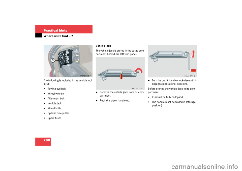
280 Practical hintsWhere will I find ...?The following is included in the vehicle tool
kit3:�
Towing eye bolt
�
Wheel wrench
�
Alignment bolt
�
Vehicle jack
�
Wheel bolts
�
Special fuse puller
�
Spare fusesVehicle jack
The vehicle jack is stored in the cargo com-
partment behind the left trim panel.
�
Remove the vehicle jack from its com-
partment.
�
Push the crank handle up.
�
Turn the crank handle clockwise until it
engages (operational position).
Before storing the vehicle jack in its com-
partment:
�
It should be fully collapsed
�
The handle must be folded in (storage
position)
S203 MY03_A.book Page 280 Tuesday, January 28, 2003 2:22 PM
Page 275 of 370

281 Practical hints
Where will I find ...?
Spare wheel
Your vehicle is equipped with either a
spare wheel with full size tire or a Mini-
spare wheel. Full size spare tire has mark-
ing “205/55 R16” on sidewall. Minispare
has marking “T125/90 R16” on sidewall.
Identify the spare tire in your vehicle and
follow appropriate instructions.
Vehicles with full size tire spare wheel
The spare wheel is located under the cargo
floor.�
Open storage compartment under car-
go floor (
�page 197).1Spare wheel
2Luggage bowl
Removing the spare wheel
�
Turn luggage bowl2 counterclockwise.
�
Remove spare wheel1.
Storing the spare wheel
�
Place spare wheel1 in wheel well.
�
Turn luggage bowl2 clockwise to its
stop to secure the spare wheel.
Warning!
G
The jack is designed exclusively for jacking
up the vehicle at the jack take-up brackets
built into both sides of the vehicle. To help
avoid personal injury, use the jack only to lift
the vehicle during a wheel change. Never
get beneath the vehicle while it is supported
by the jack. Keep hands and feet away from
the area under the lifted vehicle. Always
firmly set parking brake and block wheels
before raising vehicle with jack.
Do not disengage parking brake while the
vehicle is raised. Be certain that the jack is
always vertical (plumb line) when in use, es-
pecially on hills. Always try to use the jack
on level surface. Make sure that the jack
arm is fully seated in the jack take-up brack-
et. Always lower the vehicle onto sufficient
capacity jackstands before working under
the vehicle.
S203 MY03_A.book Page 281 Tuesday, January 28, 2003 2:22 PM
Page 277 of 370

283 Practical hints
Where will I find ...?
3Arrow
4Minispare wheel
5Luggage bowl�
Remove luggage bowl5.
�
Remove Minispare wheel4.Storing the Minispare wheel
�
Place Minispare wheel4 in wheel well.
�
Place luggage bowl5 in Minispare
wheel.
�
Place storage well casing2 and turn
the retaining screw1 clockwise as far
as it will go to secure the Minispare
wheel.
In the case of a flat tire, you may tempo-
rarily use the Minispare wheel when ob-
serving the following restrictions:
�
Do not exceed a vehicle speed of
50 mph (80 km/h).
�
Drive to the nearest tire repair facility
to have the flat tire repaired or re-
placed as appropriate.
�
Do not operate vehicle with more than
one Minispare wheel mounted.
More information can be found in the
“Technical data” section (
�page 317).
iThe arrow3 on luggage bowl5 must
point in the direction of travel, other-
wise you cannot place the storage well
casing on top and secure the Minispare
wheel with the retaining screw.
Warning!
G
The dimensions of the Minispare wheel are
different from those of the road wheels. As
a result, the vehicle handling characteristics
change when driving with a Minispare wheel
mounted.
The spare wheel should only be used tempo-
rarily, and replaced with a regular road
wheel as quick as possible.
S203 MY03_A.book Page 283 Tuesday, January 28, 2003 2:22 PM
Page 282 of 370
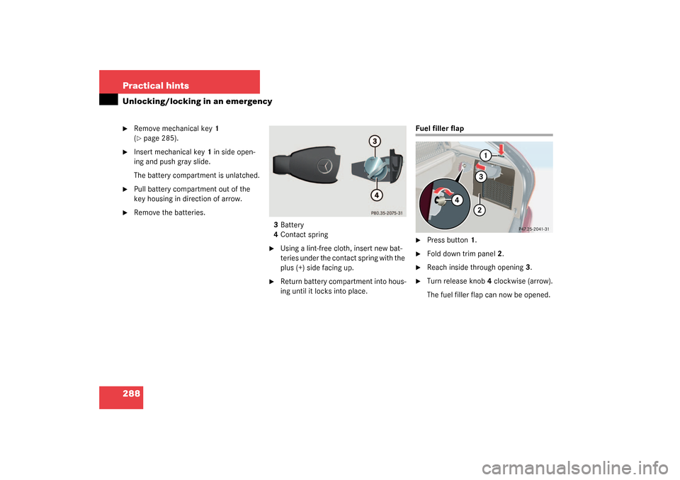
288 Practical hintsUnlocking/locking in an emergency�
Remove mechanical key1
(�page 285).
�
Insert mechanical key1 in side open-
ing and push gray slide.
The battery compartment is unlatched.
�
Pull battery compartment out of the
key housing in direction of arrow.
�
Remove the batteries.
3Battery
4Contact spring
�
Using a lint-free cloth, insert new bat-
teries under the contact spring with the
plus (+) side facing up.
�
Return battery compartment into hous-
ing until it locks into place.
Fuel filler flap�
Press button1.
�
Fold down trim panel2.
�
Reach inside through opening3.
�
Turn release knob4 clockwise (arrow).
The fuel filler flap can now be opened.
S203 MY03_A.book Page 288 Tuesday, January 28, 2003 2:22 PM
Page 284 of 370
290 Practical hintsOpening/closing in an emergency
Opening/closing in an emergencySliding/pop-up roof
The sliding/pop-up roof drive is located
behind the lens of the interior overhead
light.
You can open or close the sliding/pop-up
roof manually should an electrical malfunc-
tion occur.�
Pry off lens1 using a flat blade screw-
driver.
�
Slide both locking tabs2 in direction of
arrow.
�
Lower rear of cover and remove.
�
Remove cover.
�
Obtain crank3.
�
Insert crank3 through hole.
�
Turn crank3 clockwise to:�
slide roof closed
�
raise roof at the rear
iDo not disconnect electrical connec-
tors.
S203 MY03_A.book Page 290 Tuesday, January 28, 2003 2:22 PM