Page 23 of 356

23
At a glance
Instrument cluster
Item
Page
1
Reset knob for:�
Resetting trip odome-
ter
103
�
Instrument cluster illu-
mination
102
�
Resetting individual
settings
114
2
Tachometer with:?
Engine malfunction
indicator lamp
250
-
Antilock Brake Sys-
tem (ABS) malfunc-
tion indicator lamp
247
;
Brake warning
lamp, except Cana-
da
249
3
Brake warning
lamp, Canada only
249
Item
Page
3
Speedometer with:L
Left turn signal indi-
cator lamp
K
Right turn signal in-
dicator lamp
v
Electronic Stability
Program (ESP)
warning lamp
246
A
High beam head-
lamp indicator
99
E
Indicator lamp with-
out function
1
1The indicator lamp illuminates briefly when you
turn the key in the starter switch to position
2
DTRIndicator lamp with-
out function
1
Item
Page
4
Multifunction display
with:Trip odometer
103
Main odometerOutside temperature dis-
play
104
Digital clock
116
5
Display for program
mode and selector lever
position
135
136
6
Fuel gauge with:Fuel reserve warning lamp
250
<
Seat belt nonusage
warning lamp
250
1
Supplemental re-
straint system indi-
cator lamp
248
Page 102 of 356
.
The instrument")
102 Controls in detailInstrument cluster
Instrument clusterA full view illustration of the instrument
cluster can be found in the “At a glance”
section of this manual (
�page 22).
The instrument cluster is activated when
you:
�
open a door
�
turn on the ignition
�
press the reset knob (
�page 22)
�
switch on the exterior lamps
You can change the instrument cluster set-
tings in the Instrument cluster submenu of
the control system (
�page 116).
Instrument cluster illumination
Use the reset knob (
�page 22) to adjust
the illumination brigh tness for the instru-
ment cluster.
To brighten illumination
�
Turn the reset knob in the instrument
cluster (
�page 22) clockwise.
The instrument cluster illumination will
brighten. To dim illumination
�
Turn the reset knob
in the instrument
cluster (
�page 22) counterclockwise.
The instrument cluster illumination will
dim.
Coolant temperature gauge
iThe instrument cluster illumination is
dimmed or brightened automatically to
suit ambient light conditions.
The instrument cluster illumination will
also be adjusted automatically when
you switch on the vehicle’s exterior
lamps.
Warning!
G
�
Driving when your engine is badly over-
heated can cause some fluids which
may have leaked into the engine com-
partment to catch fire. You could be se-
riously burned.
�
Steam from an overheated engine can
cause serious burns and can occur just
by opening the engine hood. Stay away
f r o m t h e e n g i n e i f y o u s e e o r h e a r s t e a m
coming from it.
Turn off the engine, get out of the vehicle
and do not stand near the vehicle until it
cools down.
Page 105 of 356

105
Controls in detail
Control system
Control system
The control system is activated as soon as
the key in the starter switch is turned to
position 1. The control system enables you
to�
call up information about your vehicle
�
change vehicle settings
For example, you can use the control sys-
tem to find out when your vehicle is next
due for service, to set the language for
messages in the instrument cluster dis-
play, and much more.
The control system relays information to
the multifunction display.
Multifunction display
1 Main odometer
2 Trip odometer
3 Automatic transmission program mode
4 Current gear selector lever position
5 Digital clock
6 Outside temperature
iThe displays for the audio systems (ra-
dio, CD player, cassette player) will ap-
pear in English, regardless of the
language selected.
Warning!
G
A driver’s attention to the road and traffic
conditions must always be his /her primary
focus when driving.
For your safety and the safety of others, se-
lecting features through the multifunction
steering wheel should only be done by the
driver when traffic and road conditions per-
mit it to be done safely.
Bear in mind that at a speed of just 30 mph
(approximately 50 km/h), your vehicle is
covering a distance of 44 feet (approximate-
ly 13.5 m) every second.
Page 271 of 356
271
Practical hints
Where will I find ...?
Where will I find ...?
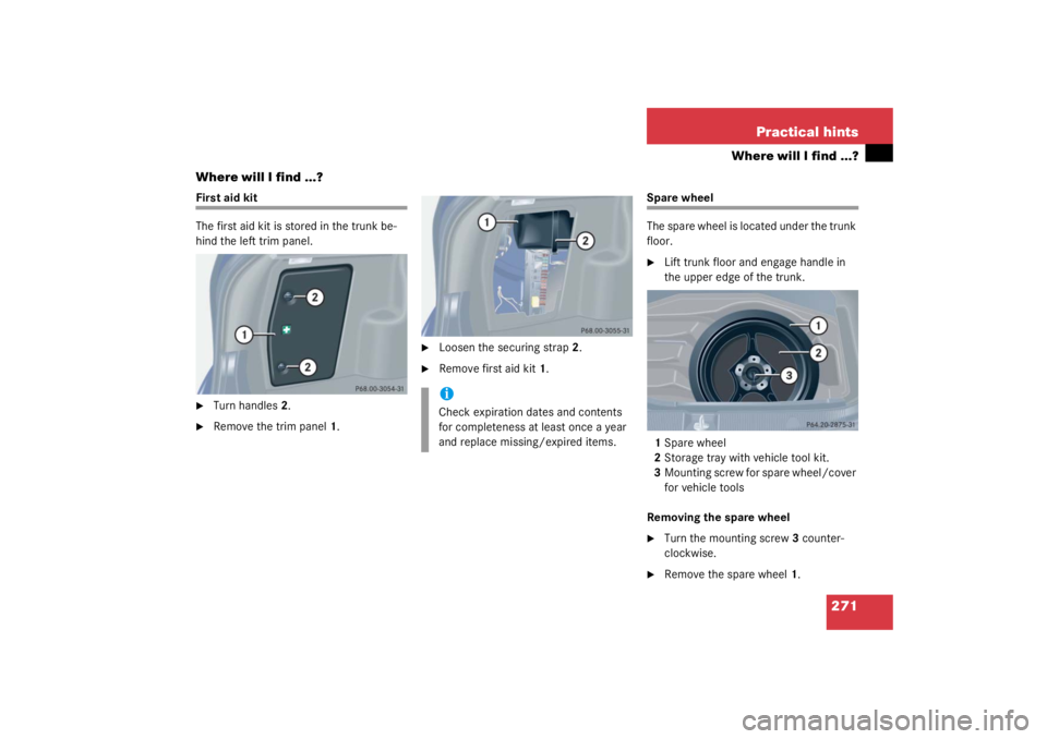
First aid kit
The first aid kit is stored in the trunk be-
hind the left trim panel.�
Turn handles 2.
�
Remove the trim panel 1.
�
Loosen the securing strap 2.
�
Remove first aid kit 1.
Spare wheel
The spare wheel is located under the trunk
floor.�
Lift trunk floor and engage handle in
the upper edge of the trunk.
1 Spare wheel
2 Storage tray with vehicle tool kit.
3 Mounting screw for spare wheel/cover
for vehicle tools
Removing the spare wheel
�
Turn the mounting screw 3 counter-
clockwise.
�
Remove the spare wheel 1.
iCheck expiration dates and contents
for completeness at least once a year
and replace missing/expired items.
Page 272 of 356
272 Practical hintsWhere will I find ...?Storing the spare wheel�
Place spare wheel1 in wheel well.
�
Turn mounting screw 3 clockwise to its
stop to secure the spare wheel.
�
Lower the trunk floor before closing the
trunk lid.
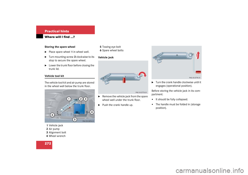
Vehicle tool kit
The vehicle tool kit and air pump are stored
in the wheel well below the trunk floor.
1 Vehicle jack
2 Air pump
3 Alignment bolt
4 Wheel wrench 5
Towing eye bolt
6 Spare wheel bolts
Vehicle jack
�
Remove the vehicle jack from the spare
wheel well under the trunk floor.
�
Push the crank handle up.
�
Turn the crank handle clockwise until it
engages (operational position).
Before storing the vehicle jack in its com-
partment:
�
It should be fully collapsed.
�
The handle must be folded in (storage
position).
Page 277 of 356
277
Practical hints
Unlocking/locking in an emergency
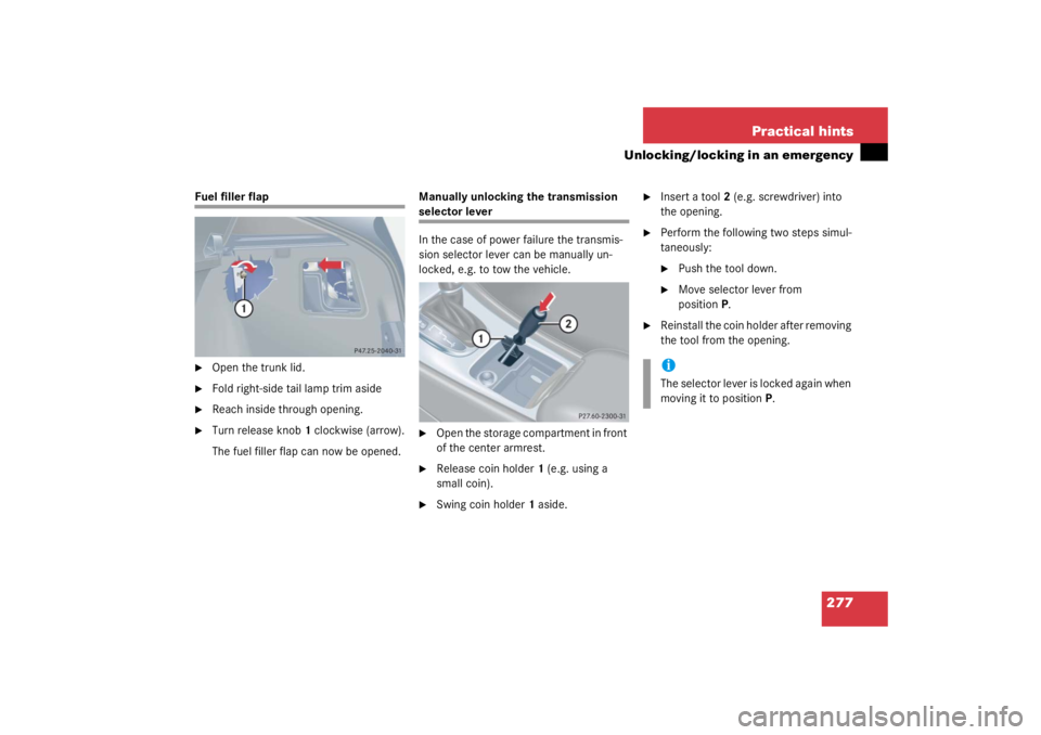
Fuel filler flap�
Open the trunk lid.
�
Fold right-side tail lamp trim aside
�
Reach inside through opening.
�
Turn release knob
1 clockwise (arrow).
The fuel filler flap can now be opened. Manually unlocking the transmission
selector lever
In the case of power failure the transmis-
sion selector lever can be manually un-
locked, e.g. to tow the vehicle.�
Open the storage compartment in front
of the center armrest.
�
Release coin holder
1 (e.g. using a
small coin).
�
Swing coin holder 1 aside.
�
Insert a tool 2 (e.g. screwdriver) into
the opening.
�
Perform the following two steps simul-
taneously:�
Push the tool down.
�
Move selector lever from
position P.
�
Reinstall the coin holder after removing
the tool from the opening.iThe selector lever is locked again when
moving it to position P.
Page 278 of 356
278 Practical hintsOpening/closing in an emergency
Opening/closing in an emergencyPanorama sliding/pop-up roof
The panorama sliding/pop-up roof drive is
located behind the lens of the interior over-
head light.
You can open or close the panorama slid-
ing/pop-up roof manually should an elec-
trical malfunction occur.�
Pry off lens1 using a screwdriver.
�
Slide both locking tabs 2 in direction of
arrow.
�
Lower rear of cover and remove.
�
Remove cover.
�
Obtain crank 3.
�
Insert crank 3 through left hand side
motor hole 4.
�
Turn crank 3 clockwise to:�
slide roof closed
�
raise roof at the rear
�
Turn crank 3 counterclockwise to:�
slide roof open
�
lower roof at the rear
The panorama sliding/pop-up roof must be
resynchronized after being operated man-
ually.
iDo not disconnect electrical connec-
tors.
Page 285 of 356
285
Practical hints
Replacing bulbs
Side marker lamp bulb�
Switch off the lights.
�
Carefully slide lamp towards rear.
�
Remove front end first.
�
Twist bulb socket counterclockwise
and pull out.
�
Pull bulb out of the bulb socket.
�
Insert new bulb in socket.
�
Reinstall bulb socket, push in and twist
clockwise.
�
To reinstall lamp, set rear end in
bumper and let front end snap into
place.
Replacing bulbs for rear lamps
Tail lamp assemblies�
Switch off the lights.
�
Open the trunk lid (
�page 85).
�
Turn handles
2.
�
Remove the trim panel 1.
�
Press together the latches 1.
�
Remove bulb holder.
�
Gently push bulb into socket, turn
counterclockwise and remove.
�
Insert new bulb and reinstall bulb sock-
et.
�
Reinstall trim panel.