Page 8 of 288
These are some of the symbols you may see on your vehicle.
Vehicle Symbol Glossary
Safety Alert
See Owner’s Guide
Fasten Safety BeltAir Bag-Front
Air Bag-SideChild Seat
Child Seat Installation
WarningChild Seat Lower
Anchor
Child Seat Tether
AnchorBrake System
Anti-Lock Brake SystemBrake Fluid -
Non-Petroleum Based
Traction ControlAdvanceTrac
Master Lighting SwitchHazard Warning Flasher
Fog Lamps-FrontFuse Compartment
Fuel Pump ResetWindshield Wash/Wipe
Windshield
Defrost/DemistRear Window
Defrost/Demist
Introduction
8
Page 9 of 288
Vehicle Symbol Glossary
Power Windows
Front/Rear
Power Window Lockout
Child Safety Door
Lock/UnlockInterior Luggage
Compartment Release
Symbol
Panic AlarmEngine Oil
Engine CoolantEngine Coolant
Temperature
Do Not Open When HotBattery
Avoid Smoking, Flames,
or SparksBattery Acid
Explosive GasFan Warning
Power Steering FluidMaintain Correct Fluid
LevelMAX
MIN
Emission SystemEngine Air Filter
Passenger Compartment
Air FilterJack
Check fuel capLow tire warning
Introduction
9
Page 83 of 288

Replacing headlamp bulbs - lowbeam
1. Remove the headlamp assembly
as described under theReplacing
exterior bulbheader.
2. Remove the four T20 torx head
screws holding the bulb retaining
cover on.
3. Turn the bulb counterclockwise
and remove it by pulling the bulb
straight out.
4. Disconnect the electrical
connector.
Handle a halogen headlamp bulb carefully and keep out of
children’s reach. Grasp the bulb only by its plastic base and do
not touch the glass. The oil from your hand could cause the bulb to
break the next time the headlamps are operated.
Install the new bulb in reverse order, while also replacing the seal on the
bulb retaining cover. The kits for replacement seals are avaliable at
Lincoln or Ford dealers.
Replacing HID headlamp bulb (if equipped)
The low beam headlamps on your vehicle use a“high intensity discharge”
source. These lamps operate at a high voltage. The bulb is NOT
replaceable. When the bulb is burned out, the lamp assembly must be
replaced by your dealer or a qualified technician.
Replacing headlamp bulbs - highbeam
1. Remove the headlamp assembly
as described under theReplacing
exterior bulbheader.
2. Remove the four T20 torx head
screws holding the bulb retaining
cover on.
3. Turn the bulb counterclockwise
and remove it by pulling the bulb
straight out.
4. Disconnect the electrical
connector.
Lights
83
Page 102 of 288

•To close from the vent, intermediate and full open positions, push the
rear portion of the control forward.
Do not let children play with the moon roof. They may seriously
hurt themselves.
When closing the moon roof, you should verify they are free of
obstructions and ensure that children and/or pets are not in the
proximity of the window openings.
Bounce Back
When an obstacle has been detected in the moon roof opening as the
moon roof is closing, the moon roof will automatically open and stop at a
prescribed position.
Bounce Back Override
To override Bounce Back, within 2 seconds after reaching Bounce Back
position, if the switch is moved from the Neutral to the auto close
positionthe moon roof will close with no bounce back protection.
If the switch is released before the moon roof reaches fully closed
position, the moon roof will stop. For example: Bounce Back Override
can be used to overcome the resistance of ice on the moon roof or seals.
HOMELINK�UNIVERSAL TRANSCEIVER (IF EQUIPPED)
The HomeLink�Universal Transceiver, located on the driver’s visor,
provides a convenient way to replace up to three hand-held transmitters
with a single built-in device. This feature will learn the radio frequency
codes of most current transmitters to operate garage doors, entry gate
operators, security systems, entry door locks, and home or office lighting.
When programming your HomeLink�Universal Transceiver to a
garage door or gate, be sure that people and objects are out of
the way to prevent potential harm or damage.
Do not use the HomeLink�Universal Transceiver with any garage door
opener that lacks safety stop and reverse features as required by U.S.
federal safety standards (this includes any garage door opener model
manufactured before April 1, 1982). A garage door which cannot detect
an object, signaling the door to stop and reverse, does not meet current
U.S. federal safety standards. For more information, contact HomeLink�
at:www.homelink.comor1–800–355–3515.
Driver Controls
102
Page 121 of 288

Note:The ignition must be in the OFF position and the accessory delay
feature must not be activated in order for this feature to operate.
Closing all windows and moonroof (if equipped)
Note:This operation is only available using the door key.
You can close the vehicle’s windows and moonroof (if equipped) by using
the door key.
Turn the key toward the back of the vehicle and hold it for more than
two seconds to begin to close all the windows and moonroof. Releasing
the key to the center position will stop all motion.
Note:The ignition must be in the OFF position and the accessory delay
feature must not be activated in order for this feature to operate.
The rear windows do not have bounce-back protection. If an
obstruction occurs, turn the key toward the front of the vehicle
and hold for more than two seconds in order to reopen all the windows
and moonroof.
Before operating power windows and moonroofs, you should
verify that they are free of obstructions and ensure that children
and/or pets are not in the proximity of window openings.
Central locking/Two stage unlocking
When unlocking the driver door with the key, turn it once toward the
front of the vehicle to unlock that door only, if the two-stage unlocking is
enabled. Turn the key a second time to unlock all doors. When locking,
turn the key toward the back of the vehicle to lock all doors.
Two stage unlocking may be disabled (and the vehicle may be
programmed for all vehicle doors to unlock by pressing the
control or
by turning the key inside the driver’s door key cylinder once toward the
front of the vehicle) by simultaneously pressing the
andcontrols
on the remote entry transmitter for four seconds.
Note:The turn lamps will flash twice to confirm that a change to the
feature has occurred.
Locks and Security
121
Page 122 of 288

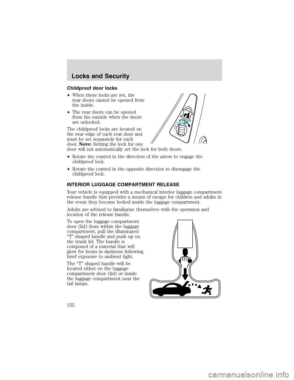
Childproof door locks
•When these locks are set, the
rear doors cannot be opened from
the inside.
•The rear doors can be opened
from the outside when the doors
are unlocked.
The childproof locks are located on
the rear edge of each rear door and
must be set separately for each
door.Note:Setting the lock for one
door will not automatically set the lock for both doors.
•Rotate the control in the direction of the arrow to engage the
childproof lock.
•Rotate the control in the opposite direction to disengage the
childproof lock.
INTERIOR LUGGAGE COMPARTMENT RELEASE
Your vehicle is equipped with a mechanical interior luggage compartment
release handle that provides a means of escape for children and adults in
the event they become locked inside the luggage compartment.
Adults are advised to familiarize themselves with the operation and
location of the release handle.
To open the luggage compartment
door (lid) from within the luggage
compartment, pull the illuminated
“T”shaped handle and push up on
the trunk lid. The handle is
composed of a material that will
glow for hours in darkness following
brief exposure to ambient light.
The“T”shaped handle will be
located either on the luggage
compartment door (lid) or inside
the luggage compartment near the
tail lamps.
Locks and Security
122
Page 123 of 288

Keep vehicle doors and
luggage compartment
locked and keep keys and remote
transmitters out of a child’s reach.
Unsupervised children could lock
themselves in the trunk and risk
injury. Children should be taught
not to play in vehicles.
On hot days, the temperature in the trunk or vehicle interior can
rise very quickly. Exposure of people or animals to these high
temperatures for even a short time can cause death or serious
heat-related injuries, including brain damage. Small children are
particularly at risk.
REMOTE ENTRY SYSTEM
This device complies with part 15 of the FCC rules and with RS-210 of
Industry Canada. Operation is subject to the following two conditions:
(1) This device may not cause harmful interference, and (2) This device
must accept any interference received, including interference that may
cause undesired operation.
Changes or modifications not expressly approved by the party
responsible for compliance could void the user’s authority to
operate the equipment.
The remote entry system allows you to perform the following tasks using
the remote entry transmitter:
•unlock the vehicle doors.
•lock all the vehicle doors.
•open the trunk.
•activate the personal alarm.
•open all windows and moonroof
(if equipped).
•arm and disarm the perimeter
anti-theft system.
•operate the illuminated entry
feature.
Locks and Security
123
Page 148 of 288

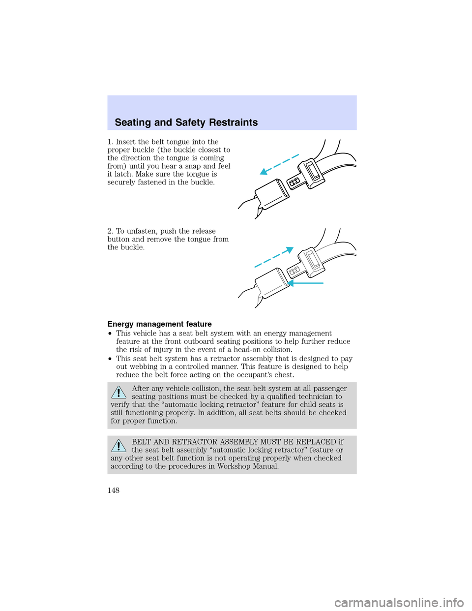
1. Insert the belt tongue into the
proper buckle (the buckle closest to
the direction the tongue is coming
from) until you hear a snap and feel
it latch. Make sure the tongue is
securely fastened in the buckle.
2. To unfasten, push the release
button and remove the tongue from
the buckle.
Energy management feature
•This vehicle has a seat belt system with an energy management
feature at the front outboard seating positions to help further reduce
the risk of injury in the event of a head-on collision.
•This seat belt system has a retractor assembly that is designed to pay
out webbing in a controlled manner. This feature is designed to help
reduce the belt force acting on the occupant’s chest.
After any vehicle collision, the seat belt system at all passenger
seating positions must be checked by a qualified technician to
verify that the“automatic locking retractor”feature for child seats is
still functioning properly. In addition, all seat belts should be checked
for proper function.
BELT AND RETRACTOR ASSEMBLY MUST BE REPLACED if
the seat belt assembly“automatic locking retractor”feature or
any other seat belt function is not operating properly when checked
according to the procedures in Workshop Manual.
Seating and Safety Restraints
148