Page 55 of 280
TILT STEERING WHEEL (IF EQUIPPED)
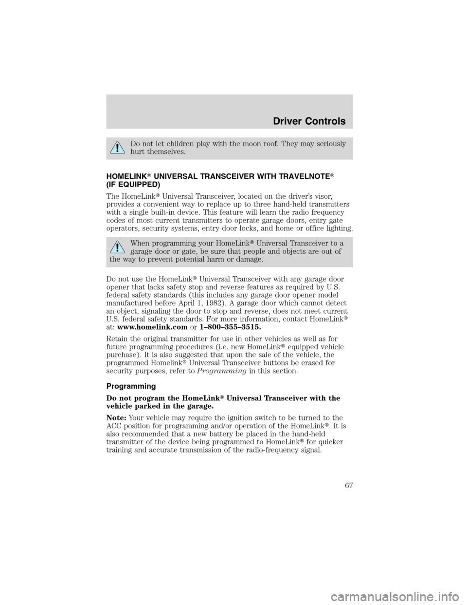
To adjust the steering wheel:
1. Pull and hold the steering wheel
release control toward you.
2. Move the steering wheel up or
down until you find the desired
location.
3. Release the steering wheel
release control. This will lock the
steering wheel in position.
Never adjust the steering wheel when the vehicle is moving.
ILLUMINATED VISOR MIRROR (IF EQUIPPED)
Lift the mirror cover to turn on the
visor mirror lamps.
OVERHEAD CONSOLE (IF EQUIPPED)
The appearance of your vehicle’s overhead console will vary according to
your option package.
Driver Controls
55
Page 61 of 280

One touch down
Allows the driver’s window to open
fully without holding the control
down. Press completely down on
AUTO and release quickly. Press
again to stop.
Accessory delay (if equipped)
With accessory delay, the window switches may be used for up to ten
minutes after the ignition switch is turned to the OFF position or until
any door is opened.
MIRRORS
Automatic dimming rear view mirrors (if equipped)
Your vehicle is equipped with an inside rear view mirror with an
auto-dimming function. The electronic day/night mirror will change from
the normal state to the non-glare state when bright lights (glare) reach
the inside rear view mirror. When the inside rear view mirror detects
bright light from behind the vehicle, the inside rear view mirror will
automatically adjust (darken) to minimize glare.
Do not block the sensor on the backside of the inside rear view mirror
since this may impair proper system performance.
Press the control to turn the mirror
OFF or AUTO.
The mirror will automatically return
to the normal state whenever the
vehicle is placed in R
(Reverse)(when the mirror is on) to ensure a bright clear view when
backing up.
OFF AUTO
Driver Controls
61
Page 67 of 280

Do not let children play with the moon roof. They may seriously
hurt themselves.
HOMELINK�UNIVERSAL TRANSCEIVER WITH TRAVELNOTE�
(IF EQUIPPED)
The HomeLink�Universal Transceiver, located on the driver’s visor,
provides a convenient way to replace up to three hand-held transmitters
with a single built-in device. This feature will learn the radio frequency
codes of most current transmitters to operate garage doors, entry gate
operators, security systems, entry door locks, and home or office lighting.
When programming your HomeLink�Universal Transceiver to a
garage door or gate, be sure that people and objects are out of
the way to prevent potential harm or damage.
Do not use the HomeLink�Universal Transceiver with any garage door
opener that lacks safety stop and reverse features as required by U.S.
federal safety standards (this includes any garage door opener model
manufactured before April 1, 1982). A garage door which cannot detect
an object, signaling the door to stop and reverse, does not meet current
U.S. federal safety standards. For more information, contact HomeLink�
at:www.homelink.comor1–800–355–3515.
Retain the original transmitter for use in other vehicles as well as for
future programming procedures (i.e. new HomeLink�equipped vehicle
purchase). It is also suggested that upon the sale of the vehicle, the
programmed Homelink�Universal Transceiver buttons be erased for
security purposes, refer toProgrammingin this section.
Programming
Do not program the HomeLink�Universal Transceiver with the
vehicle parked in the garage.
Note:Your vehicle may require the ignition switch to be turned to the
ACC position for programming and/or operation of the HomeLink�.Itis
also recommended that a new battery be placed in the hand-held
transmitter of the device being programmed to HomeLink�for quicker
training and accurate transmission of the radio-frequency signal.
Driver Controls
67
Page 69 of 280

8. Return to the vehicle and firmly press, hold for two seconds and
release the HomeLink�button. Repeat the press/hold/release sequence
again, and, depending on the brand of the garage door opener (or other
rolling code equipped device), repeat this sequence a third time to
complete the programming.
HomeLink�should now activate your rolling code equipped device. To
program additional HomeLink�buttons begin with step 2 in the
“Programming”section. For questions or comments, please contact
HomeLink atwww.homelink.comor1–800–355–3515.
Operating the HomeLink�Universal Transceiver
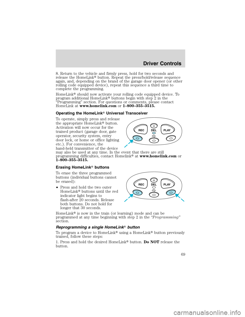
To operate, simply press and release
the appropriate HomeLink�button.
Activation will now occur for the
trained product (garage door, gate
operator, security system, entry
door lock, or home or office lighting
etc.). For convenience, the
hand-held transmitter of the device
may also be used at any time. In the event that there are still
programming difficulties, contact Homelink�atwww.homelink.comor
1–800–355–3515.
Erasing HomeLink�buttons
To erase the three programmed
buttons (individual buttons cannot
be erased):
•Press and hold the two outer
HomeLink�buttons until the red
indicator light begins to
flash-after 20 seconds. Release
both buttons. Do not hold for
longer that 30 seconds.
HomeLink�is now in the train (or learning) mode and can be
programmed at any time beginning with step 2 in the“Programming”
section.
Reprogramming a single HomeLink�button
To program a device to HomeLink�using a HomeLink�button previously
trained, follow these steps:
1. Press and hold the desired HomeLink�button.Do NOTrelease the
button.
REC DEL PLAY
REC DEL PLAY
Driver Controls
69
Page 72 of 280
If theDELbutton is inadvertently pressed or the time allotted (five
seconds) has passed, the indicator light will flash amber and an“error”
tone will sound.
POSITIVE RETENTION FLOOR MAT (IF EQUIPPED)
Position the floor mat so that the
eyelet is over the pointed end of the
retention post and rotate forward to
lock in. Make sure that the mat does
not interfere with the operation of
the accelerator or the brake pedal.
To remove the floor mat, reverse the
installation procedure.
TAILGATE LOCK (IF EQUIPPED)
Your vehicle may be equipped with a
tailgate lock designed to prevent
theft of the tailgate.
•Insert ignition key and turn to the
right to engage lock.
•Turn ignition key to the left to
unlock.
Driver Controls
72
Page 73 of 280

TAILGATE REMOVAL
Your tailgate is removable to allow
more room for loading.
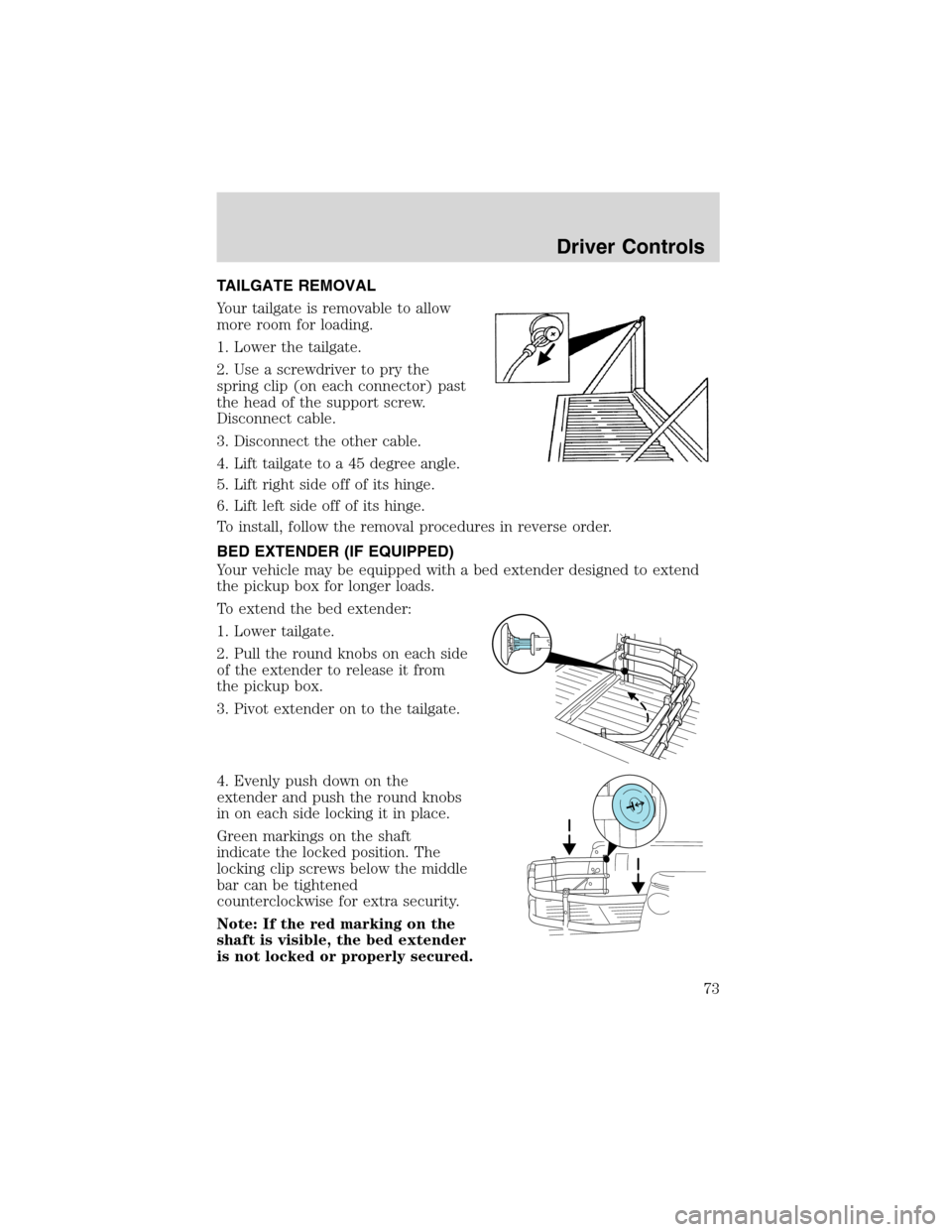
1. Lower the tailgate.
2. Use a screwdriver to pry the
spring clip (on each connector) past
the head of the support screw.
Disconnect cable.
3. Disconnect the other cable.
4. Lift tailgate to a 45 degree angle.
5. Lift right side off of its hinge.
6. Lift left side off of its hinge.
To install, follow the removal procedures in reverse order.
BED EXTENDER (IF EQUIPPED)
Your vehicle may be equipped with a bed extender designed to extend
the pickup box for longer loads.
To extend the bed extender:
1. Lower tailgate.
2. Pull the round knobs on each side
of the extender to release it from
the pickup box.
3. Pivot extender on to the tailgate.
4. Evenly push down on the
extender and push the round knobs
in on each side locking it in place.
Green markings on the shaft
indicate the locked position. The
locking clip screws below the middle
bar can be tightened
counterclockwise for extra security.
Note: If the red marking on the
shaft is visible, the bed extender
is not locked or properly secured.
Driver Controls
73
Page 74 of 280

To stow the bed extender, follow steps one through four in reverse order.
The bed extender may be used to secure a load of up to 46 kg (100 lbs.)
on the tailgate.
The bed extender should always be kept in the stowed position
with the tailgate closed when not in use.
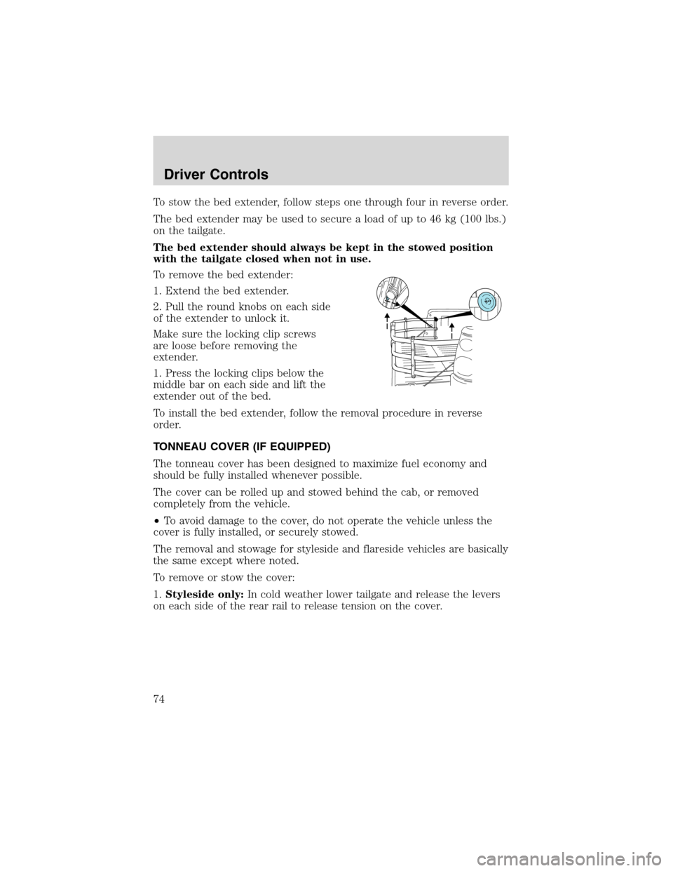
To remove the bed extender:
1. Extend the bed extender.
2. Pull the round knobs on each side
of the extender to unlock it.
Make sure the locking clip screws
are loose before removing the
extender.
1. Press the locking clips below the
middle bar on each side and lift the
extender out of the bed.
To install the bed extender, follow the removal procedure in reverse
order.
TONNEAU COVER (IF EQUIPPED)
The tonneau cover has been designed to maximize fuel economy and
should be fully installed whenever possible.
The cover can be rolled up and stowed behind the cab, or removed
completely from the vehicle.
•To avoid damage to the cover, do not operate the vehicle unless the
cover is fully installed, or securely stowed.
The removal and stowage for styleside and flareside vehicles are basically
the same except where noted.
To remove or stow the cover:
1.Styleside only:In cold weather lower tailgate and release the levers
on each side of the rear rail to release tension on the cover.
Driver Controls
74
Page 76 of 280
Flareside only:
•Remove two cross bars from pickup box by pushing towards either
side to release tension.
•Lower tailgate, depress the levers on each side of the rear rail and
remove rear rail from pickup box.
Styleside only:
•Remove three cross bars from
pickup box by pushing towards
either side to release tension.
Stow the cross bars in the
notches behind the rolled cover
in the pickup box.
•Lower tailgate, depress the levers
on each side of the rear rail and
push rear rail towards the front of
the pickup box securing it behind
the cross bars and cover.
For installation of the cover, follow the removal procedure in reverse
order.
Make sure the crossbows are locked in the notches in the side rails and
the rear rails are locked in position prior to cover installation.
Driver Controls
76