Page 2416 of 4500

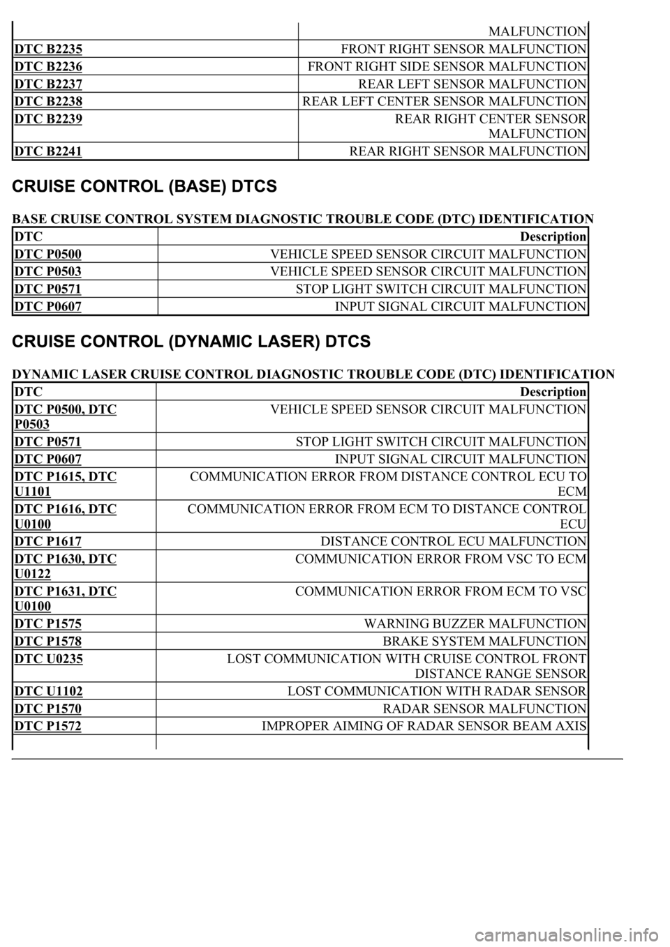
BASE CRUISE CONTROL SYSTEM DIAGNOSTIC TROUBLE CODE (DTC) IDENTIFICATION
DYNAMIC LASER CRUISE CONTROL DIAGNOSTIC TROUBLE CODE (DTC) IDENTIFICATION
MALFUNCTION
DTC B2235 FRONT RIGHT SENSOR MALFUNCTION
DTC B2236 FRONT RIGHT SIDE SENSOR MALFUNCTION
DTC B2237 REAR LEFT SENSOR MALFUNCTION
DTC B2238 REAR LEFT CENTER SENSOR MALFUNCTION
DTC B2239 REAR RIGHT CENTER SENSOR
MALFUNCTION
DTC B2241 REAR RIGHT SENSOR MALFUNCTION
DTCDescription
DTC P0500 VEHICLE SPEED SENSOR CIRCUIT MALFUNCTION
DTC P0503 VEHICLE SPEED SENSOR CIRCUIT MALFUNCTION
DTC P0571 STOP LIGHT SWITCH CIRCUIT MALFUNCTION
DTC P0607 INPUT SIGNAL CIRCUIT MALFUNCTION
DTCDescription
DTC P0500, DTC
P0503
VEHICLE SPEED SENSOR CIRCUIT MALFUNCTION
DTC P0571 STOP LIGHT SWITCH CIRCUIT MALFUNCTION
DTC P0607 INPUT SIGNAL CIRCUIT MALFUNCTION
DTC P1615, DTC
U1101
COMMUNICATION ERROR FROM DISTANCE CONTROL ECU TO
ECM
DTC P1616, DTC
U0100
COMMUNICATION ERROR FROM ECM TO DISTANCE CONTROL
ECU
DTC P1617 DISTANCE CONTROL ECU MALFUNCTION
DTC P1630, DTC
U0122
COMMUNICATION ERROR FROM VSC TO ECM
DTC P1631, DTC
U0100
COMMUNICATION ERROR FROM ECM TO VSC
DTC P1575 WARNING BUZZER MALFUNCTION
DTC P1578 BRAKE SYSTEM MALFUNCTION
DTC U0235 LOST COMMUNICATION WITH CRUISE CONTROL FRONT
DISTANCE RANGE SENSOR
DTC U1102 LOST COMMUNICATION WITH RADAR SENSOR
DTC P1570 RADAR SENSOR MALFUNCTION
DTC P1572 IMPROPER AIMING OF RADAR SENSOR BEAM AXIS
Page 2417 of 4500

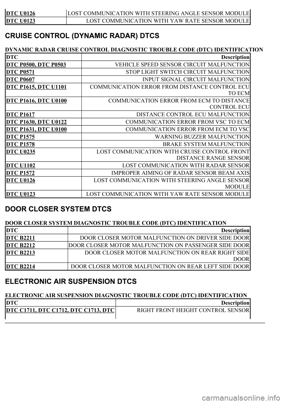
DYNAMIC RADAR CRUISE CONTROL DIAGNOSTIC TROUBLE CODE (DTC) IDENTIFICATION
DOOR CLOSER SYSTEM DIAGNOSTIC TROUBLE CODE (DTC) IDENTIFICATION
ELECTRONIC AIR SUSPENSION DIAGNOSTIC TROUBLE CODE (DTC) IDENTIFICATION
DTC U0126 LOST COMMUNICATION WITH STEERING ANGLE SENSOR MODULE
DTC U0123 LOST COMMUNICATION WITH YAW RATE SENSOR MODULE
DTCDescription
DTC P0500, DTC P0503 VEHICLE SPEED SENSOR CIRCUIT MALFUNCTION
DTC P0571 STOP LIGHT SWITCH CIRCUIT MALFUNCTION
DTC P0607 INPUT SIGNAL CIRCUIT MALFUNCTION
DTC P1615, DTC U1101 COMMUNICATION ERROR FROM DISTANCE CONTROL ECU
TO ECM
DTC P1616, DTC U0100 COMMUNICATION ERROR FROM ECM TO DISTANCE
CONTROL ECU
DTC P1617 DISTANCE CONTROL ECU MALFUNCTION
DTC P1630, DTC U0122 COMMUNICATION ERROR FROM VSC TO ECM
DTC P1631, DTC U0100 COMMUNICATION ERROR FROM ECM TO VSC
DTC P1575 WARNING BUZZER MALFUNCTION
DTC P1578 BRAKE SYSTEM MALFUNCTION
DTC U0235 LOST COMMUNICATION WITH CRUISE CONTROL FRONT
DISTANCE RANGE SENSOR
DTC U1102 LOST COMMUNICATION WITH RADAR SENSOR
DTC P1572 IMPROPER AIMING OF RADAR SENSOR BEAM AXIS
DTC U0126 LOST COMMUNICATION WITH STEERING ANGLE SENSOR
MODULE
DTC U0123 LOST COMMUNICATION WITH YAW RATE SENSOR MODULE
DTCDescription
DTC B2211 DOOR CLOSER MOTOR MALFUNCTION ON DRIVER SIDE DOOR
DTC B2212 DOOR CLOSER MOTOR MALFUNCTION ON PASSENGER SIDE DOOR
DTC B2213 DOOR CLOSER MOTOR MALFUNCTION ON REAR RIGHT SIDE
DOOR
DTC B2214 DOOR CLOSER MOTOR MALFUNCTION ON REAR LEFT SIDE DOOR
DTCDescription
DTC C1711, DTC C1712, DTC C1713, DTC RIGHT FRONT HEIGHT CONTROL SENSOR
Page 2426 of 4500

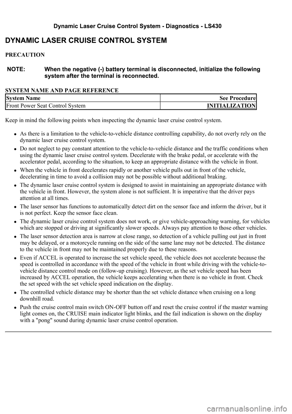
PRECAUTION
SYSTEM NAME AND PAGE REFERENCE
Keep in mind the following points when inspecting the dynamic laser cruise control system.
As there is a limitation to the vehicle-to-vehicle distance controlling capability, do not overly rely on the
dynamic laser cruise control system.
Do not neglect to pay constant attention to the vehicle-to-vehicle distance and the traffic conditions when
using the dynamic laser cruise control system. Decelerate with the brake pedal, or accelerate with the
accelerator pedal, according to the situation, to keep an appropriate distance with the vehicle in front.
When the vehicle in front decelerates rapidly or another vehicle pulls out in front of the vehicle,
decelerating in time to avoid a collision may not be possible without additional braking.
The dynamic laser cruise control system is designed to assist in maintaining an appropriate distance with
the vehicle in front. However, the system alone is not sufficient. It is imperative that the driver pays
attention at all times.
The laser sensor has functions to automatically detect dirt on the sensor face and inform the driver, but it
is not perfect. Keep the sensor face clean.
The dynamic laser cruise control system does not work, or give vehicle-approaching warning, for vehicles
which are stopped or driving at significantly slower speeds. Always pay attention to those other vehicles.
The laser sensor detection area is narrow at close range, so detection of a vehicle pulling out just in front
may be delayed, or a motorcycle running on the side of the same lane may not be detected. The distance
to the vehicle in front may not be maintained properly due to these reasons.
Even if ACCEL is operated to increase the set vehicle speed, the vehicle does not accelerate because the
speed is controlled in accordance with the speed of the vehicle in front while driving with the vehicle-to-
vehicle distance control mode on (follow-up cruising). However, as the set vehicle speed has been
increased by ACCEL operation, the vehicle keeps accelerating when there is no vehicle in front. Check
the set speed with the set vehicle speed indication on the display.
The controlled vehicle distance may be shorter than the set vehicle distance when cruising on a long
downhill road.
Push the cruise control main switch ON-OFF button off and reset the cruise control if the master warning
light comes on, the CRUISE main indicator light blinks, and the fail indication is shown on the display
with a "pong" sound during dynamic laser cruise control operation.
System NameSee Procedure
Front Power Seat Control SystemINITIALIZATION
Page 2427 of 4500
The vehicle-approaching warning buzzer does not sound in the constant speed control mode because the
existence of the vehicle in front and the distance to it are not judged as in the vehicle-to-vehicle distance
control mode. Pay attention to the distance to the vehicle in front.
The dynamic laser cruise control system has two cruise control modes: the constant speed control mode
and vehicle-to-vehicle distance control mode. Confirm which mode is selected when using the dynamic
laser cruise control system.
Page 2428 of 4500
Fig. 1: Identifying Dynamic Laser Cruise Control System Electrical Location (1 Of 2)
Courtesy of TOYOTA MOTOR SALES, U.S.A., INC.
Page 2429 of 4500
Fig. 2: Identifying Dynamic Laser Cruise Control System Electrical Location (2 Of 2)
Courtesy of TOYOTA MOTOR SALES, U.S.A., INC.
Page 2430 of 4500
Fig. 3: Wiring Diagram - Dynamic Laser Cruise Control System
Courtesy of TOYOTA MOTOR SALES, U.S.A., INC.
Input and output signals of each ECU.
Page 2432 of 4500
Fig. 5: ECU Input And Output Signals Chart (2 Of 2)
Courtesy of TOYOTA MOTOR SALES, U.S.A., INC.
1.GENERAL
a. The dynamic laser cruise control system has two cruise control modes: the constant speed control
mode and vehicle-to-vehicle distance control mode.
The vehicle-to-vehicle distance control mode is always selected when starting up the