Page 2927 of 4500
Fig. 21: Blowing Air From Intake Manifold Side Of Engine
Courtesy of TOYOTA MOTOR SALES, U.S.A., INC.
4.INSPECT FUEL TANK CAP ASSY
a. Visually check if cap and/or gasket are deformed or damaged.
If necessar
y, repair or replace the cap.
Page 2928 of 4500
Fig. 22: Inspecting Fuel Tank Cap Assy
Courtesy of TOYOTA MOTOR SALES, U.S.A., INC.
5.INSPECT PURGE VSV
a. Measure the purge VSV resistance.
Standard:
RESISTANCE CONDITION
If the result is not as specified, replace the pur
ge VSV.
Tester ConnectionSpecified Condition
1 - 226 to 30 ohms at 20°C (68°F)
1 - Body ground
2 - Body ground10 Mohms or higher
Page 2961 of 4500
REPLACEMENT
1.DRAIN ENGINE COOLANT (See ENGINE COOLANT
)
2.WORK FOR PREVENTING GASOLINE FROM SPILLING OUT (See PRECAUTION
)
3.DISCONNECT BATTERY NEGATIVE TERMINAL
4.REMOVE V-BANK COVER
5.REMOVE INTAKE AIR CONNECTOR PIPE
6.REMOVE THROTTLE BODY ASSY (See REPLACEMENT
)
7.REMOVE INTAKE MANIFOLD ASSY
Fig. 20: Disconnecting VSV Connector For EVAP
Courtesy of TOYOTA MOTOR SALES, U.S.A., INC.
a. Disconnect the fuel pipe sub-assy No. 2 from the fuel main tube (see PRECAUTION
).
b. Disconnect the VSV connector for EVAP.
c. Disconnect the EVAP hose from the VSV for EVAP.
d. Remove the bolt, disconnect the VSV for EVAP from the upper intake manifold.
e. Remove the bolt and V-bank cover bracket No. 2.
f. Remove the bolt and V-
bank cover bracket No. 3.
Page 2971 of 4500
Fig. 30: Connecting VSV Connector For EVAP
Courtesy of TOYOTA MOTOR SALES, U.S.A., INC.
Torque: 7.5 N.m (76.5 kgf.cm, 66 in..lbf)
k. Install the V-bank cover bracket No. 2 with bolt.
Torque: 7.5 N.m (76.5 kgf.cm, 66 in..lbf)
l. Install the VSV for EVAP to the intake manifold with the bolt.
Torque: 7.5 N.m (76.5 kgf.cm, 66 in..lbf)
m. Connect the EVAP hose to the VSV for EVAP.
n. Connect the VSV connector for EVAP.
11.INSTALL THROTTLE BODY ASSY (See REPLACEMENT
)
12.INSTALL INTAKE AIR CONNECTOR PIPE
13.INSPECT FUEL PUMP OPERATION AND CHECK FOR FUEL LEAKS (See ON
-VEHICLE
INSPECTION )
14.INSTALL V-BANK COVER
Torque: 5.0 N.m (51 kgf.cm, 44 in..lbf)
15.CONNECT BATTERY NEGATIVE TERMINAL
Page 3166 of 4500

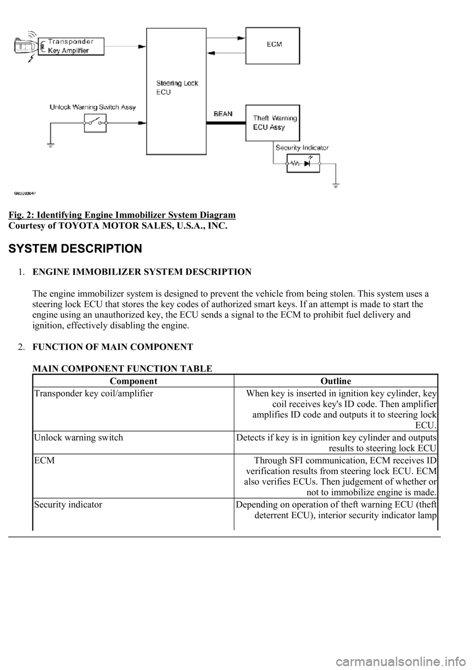
Fig. 2: Identifying Engine Immobilizer System Diagram
Courtesy of TOYOTA MOTOR SALES, U.S.A., INC.
1.ENGINE IMMOBILIZER SYSTEM DESCRIPTION
The engine immobilizer system is designed to prevent the vehicle from being stolen. This system uses a
steering lock ECU that stores the key codes of authorized smart keys. If an attempt is made to start the
engine using an unauthorized key, the ECU sends a signal to the ECM to prohibit fuel delivery and
ignition, effectively disabling the engine.
2.FUNCTION OF MAIN COMPONENT
MAIN COMPONENT FUNCTION TABLE
ComponentOutline
Transponder key coil/amplifierWhen key is inserted in ignition key cylinder, key
coil receives key's ID code. Then amplifier
amplifies ID code and outputs it to steering lock
ECU.
Unlock warning switchDetects if key is in ignition key cylinder and outputs
results to steering lock ECU
ECMThrough SFI communication, ECM receives ID
verification results from steering lock ECU. ECM
also verifies ECUs. Then judgement of whether or
not to immobilize engine is made.
Security indicatorDepending on operation of theft warning ECU (theft
deterrent ECU), interior security indicator lamp
Page 3167 of 4500

3.SYSTEM FUNCTION
When the steering lock ECU detects that the unlock warning switch is ON, the ECU provides current to
the transponder key coil and produces a faint electric wave. A transponder chip in the key and receives
the faint electric wave. Upon receiving the faint electric wave, the transponder chip outputs a key ID code
signal. The transponder key coil receives this signal, the transponder key amplifier amplifies it, and then
the signal is transmitted to the ECU.
The ECU matches the key's ID code with the vehicle's ID code, which was previously registered in the
ECU and then communicates the results to the ECM using SFI communication.
After the identification results show that the key's ID code matches the vehicle's ID code and the ECU has
confirmed their match: 1) the immobilizer system does not immobilize the engine and the engine starting
controls (fuel injection control and ignition control) enter standby mode; and 2) the ECU transmits a
security indicator signal that communicates "indicator off" to the theft warning ECU (theft deterrent
ECU). Then, the theft warning ECU turns off the security indicator lamp.
HINT:
Use this procedure to troubleshoot the engine immobilizer system.
The hand-held tester should be used in steps 4, 5 and 7.
1.VEHICLE BROUGHT TO WORKSHOP
2.CUSTOMER PROBLEM ANALYSIS CHECK AND SYMPTOM CHECK (See CUSTOMER
PROBLEM ANALYSIS CHECK )
3.CRANK ENGINE FOR MORE THAN 10 SECONDS
4.CHECK FOR DTCS
a. Check for DTCs and note any codes that are output.
b. Delete the DTC.
c. Recheck for DTCs. Based on the DTC output in (a), try to force output of the same SFI system
DTC or engine immobilizer system DTC by simulating the operation indicated by the DTC.
1. If the DTC does not reoccur, proceed to A.
2. If the SFI system DTC reoccurs, proceed to B.
3. If the engine immobilizer system DTC reoccurs, proceed to C.
B: Go to SFI SYSTEM (See HOW TO PROCEED WITH TROUBLESHOOTING
)
C: Go to step 8
illuminates or starts blinking.
Page 3226 of 4500

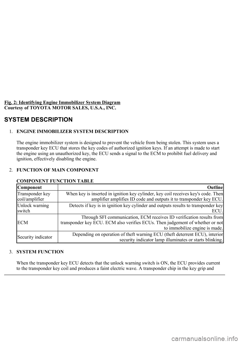
Fig. 2: Identifying Engine Immobilizer System Diagram
Courtesy of TOYOTA MOTOR SALES, U.S.A., INC.
1.ENGINE IMMOBILIZER SYSTEM DESCRIPTION
The engine immobilizer system is designed to prevent the vehicle from being stolen. This system uses a
transponder key ECU that stores the key codes of authorized ignition keys. If an attempt is made to start
the engine using an unauthorized key, the ECU sends a signal to the ECM to prohibit fuel delivery and
ignition, effectively disabling the engine.
2.FUNCTION OF MAIN COMPONENT
COMPONENT FUNCTION TABLE
3.SYSTEM FUNCTION
When the transponder key ECU detects that the unlock warning switch is ON, the ECU provides current
to the transponder ke
y coil and produces a faint electric wave. A transponder chip in the key grip and
ComponentOutline
Transponder key
coil/amplifierWhen key is inserted in ignition key cylinder, key coil receives key's code. Then
amplifier amplifies ID code and outputs it to transponder key ECU.
Unlock warning
switchDetects if key is in ignition key cylinder and outputs results to transponder key
ECU.
ECM
Through SFI communication, ECM receives ID verification results from
transponder key ECU. ECM also verifies ECUs. Then judgement of whether or not
to immobilize engine is made.
Security indicatorDepending on operation of theft warning ECU (theft deterrent ECU), interior
security indicator lamp illuminates or starts blinking.
Page 3227 of 4500

receives the faint electric wave. Upon receiving the faint electric wave, the transponder chip outputs a key
ID code signal. The transponder key coil receives this signal, the transponder key amplifier amplifies it,
and then the signal is transmitted to the ECU.
The ECU matches the key's ID code with the vehicle's ID code, which was previously registered in the
ECU, and then communicates the results to the ECM using SFI communication.
After the identification results show that the key's ID code matches the vehicle's ID code and the ECU has
confirmed their match: 1) the immobilizer system does not immobilize the engine and the engine starting
controls (fuel injection control and ignition control) enter standby mode; and 2) the ECU transmits a
security indicator signal that communicates "indicator off" to the theft warning ECU (theft deterrent
ECU). Then, the theft warning ECU turns off the security indicator lamp.
HINT:
<00380056004800030057004b004c00560003005300550052004600480047005800550048000300570052000300570055005200580045004f00480056004b00520052005700030057004b0048000300480051004a004c005100480003004c00500050005200
45004c004f004c005d0048005500030056005c005600570048[m. The hand-held tester should be used in steps
4, 5 and 7.
1.VEHICLE BROUGHT TO WORKSHOP
2.CUSTOMER PROBLEM ANALYSIS CHECK AND SYMPTOM CHECK (See CUSTOMER
PROBLEM ANALYSIS CHECK )
3.CRANK ENGINE FOR MORE THAN 10 SECONDS
4.CHECK FOR DTCS
a. Check for DTCs and note any codes that are output.
b. Delete the DTC.
c. Recheck for DTCs. Based on the DTC output in (a), try to force output of the same SFI system
DTC or engine immobilizer system DTC by simulating the operation indicated by the DTC.
1. If the DTC does not reoccur, proceed to A.
2. If the SFI system DTC reoccurs, proceed to B.
3. If the engine immobilizer system DTC reoccurs, proceed to C.
B: Go to SFI SYSTEM (See DIAGNOSTIC TROUBLE CODE CHART
)
C: Go to step 8
A: Go to next step
5.READ DATA LIST USING HAND-HELD TESTER
a. Connect the hand-held tester to the Controller Area Network Vehicle Interface Module (CAN
VIM). Then connect the CAN VIM to the DLC3.
b. Turn the ignition switch ON and push the hand-held tester main switch ON.
c. Read the DATA LIST.