Page 714 of 4500
HINT:
If the noise does not fall into any category in the table above, determine the cause using "Radio reception
problems" above. Refer to the multi-path and phasing sections.
HINT:
Before performing verification listed in the table below, check the fuse and relay.
Methods used to verify the cause of the problem are listed in order of probability in the verification
column.
AUDIO FUNCTION
Page 1570 of 4500
Courtesy of TOYOTA MOTOR SALES, U.S.A., INC.
INSPECTION PROCEDURE
1.INSPECT FUSE (RR IG FUSE)
a. Remove the RR IG fuse from the luggage room J/B.
b. Measure the resistance according to the value (s) in the table below.
Standard:
TERMINAL NUMBER SPECIFIED CONDITION
ItemConditionSpecified condition
RR IG fuseAlwaysBelow 1 ohms
Page 1571 of 4500
Fig. 60: Identifying RR IG Fuse Location
Courtesy of TOYOTA MOTOR SALES, U.S.A., INC.
NG: INSPECT FOR SHORT IN ALL COMPONENTS CONNECTED TO FUSE AND REPAIR
OR REPLACE THEM IF NEEDED, AND REPLACE FUSE
OK: Go To Next Step.
2.INSPECT CLEARANCE WARNING ECU ASSY (IG TERMINAL VOLTAGE)
a. Disconnect the C17 connector from the clearance warning ECU assy.
b. Measure the voltage according to the value (s) in the table below.
Page 1669 of 4500
NG: REPAIR OR REPLACE AIR DUCT
OK: REPLACE SEAT CLIMATE CONTROL CONTROLLER (SEATBACK OR SEAT
CUSHION)
CIRCUIT DESCRIPTION
If the climate control seat does not operate, the seat climate control blower (climate control ECU) or the wire
harness may be malfunctioning.
WIRE DIAGRAM
Fig. 51: Climate Control System Does Not Operate On Driver Side
- Wire Diagram
Courtesy of TOYOTA MOTOR SALES, U.S.A., INC.
INSPECTION PROCEDURE
1.INSPECT FUSE (D S/HTR)
a. Remove the D S/HTR fuse from the driver side J/B.
b. Measure the resistance of the fuse.
Standard: Below 1 ohms
NG: REPLACE FUSE
OK: Go to next step
2.CHECK WIRE HARNESS (SEAT CLIMATE CONTROL BLOWER (CLIMATE CONTROL
ECU) - BATTERY)
a. Disconnect the C20 blower connector.
Page 1677 of 4500
CIRCUIT DESCRIPTION
If the climate control seat does not operate, the seat climate control blower (climate control ECU) or the wire
harness may be malfunctioning.
WIRE DIAGRAM
Fig. 58: Climate Control System Does Not Operate On Passenger Side
- Wire Diagram
Courtesy of TOYOTA MOTOR SALES, U.S.A., INC.
INSPECTION PROCEDURE
1.INSPECT FUSE (P S/HTR)
a. Remove the P S/HTR fuse from the driver side J/B.
b. Measure the resistance of the relay.
Standard: Below 1 ohms
NG: REPLACE FUSE
OK: Go to next step
2.CHECK WIRE HARNESS (SEAT CLIMATE CONTROL BLOWER (CLIMATE CONTROL
ECU) - BATTERY)
a. Disconnect the C21 blower connector.
b. Measure the voltage of the wire harness side connector.
Standard:
TESTER CONNECTION AND SPECIFIED CONDITION
Tester ConnectionConditionSpecified Condition
Page 1686 of 4500
1.INSPECT FUSE (RR S/HTR)
a. Remove the RR S/HTR fuse from the luggage room J/B.
b. Measure the resistance of the relay.
Standard: Below 1 ohms
NG: REPLACE FUSE
OK: Go to next step
2.CHECK WIRE HARNESS (SEAT CLIMATE CONTROL BLOWER (CLIMATE CONTROL
ECU) - BATTERY)
a. Disconnect the C27 or C29 blower connector.
b. Measure the voltage of the wire harness side connector.
Standard:
Rear LH
TESTER CONNECTION AND SPECIFIED CONDITION
Rear RH
TESTER CONNECTION AND SPECIFIED CONDITION - REAR RH
Tester ConnectionConditionSpecified Condition
C27-10 (IG) - Body groundIgnition switch ON10 to 14 V
Tester ConnectionConditionSpecified Condition
C29-10 (IG) - Body groundIgnition switch ON10 to 14 V
Page 1756 of 4500

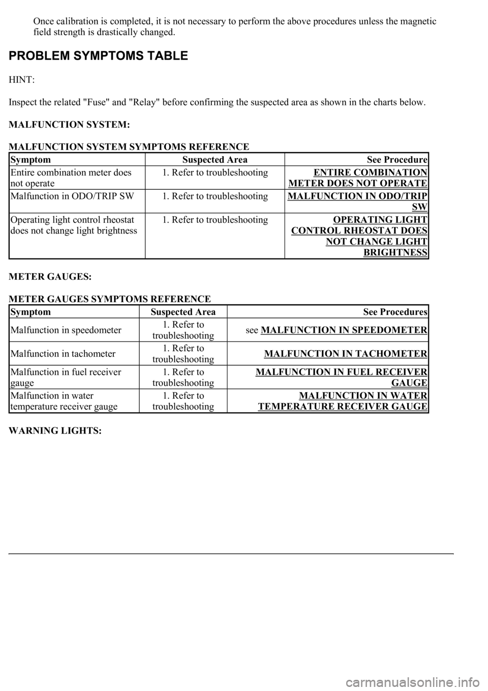
Once calibration is completed, it is not necessary to perform the above procedures unless the magnetic
field strength is drastically changed.
HINT:
Inspect the related "Fuse" and "Relay" before confirming the suspected area as shown in the charts below.
MALFUNCTION SYSTEM:
MALFUNCTION SYSTEM SYMPTOMS REFERENCE
METER GAUGES:
METER GAUGES SYMPTOMS REFERENCE
WARNING LIGHTS:
SymptomSuspected AreaSee Procedure
Entire combination meter does
not operate1. Refer to troubleshootingENTIRE COMBINATION
METER DOES NOT OPERATE
Malfunction in ODO/TRIP SW1. Refer to troubleshootingMALFUNCTION IN ODO/TRIP
SW
Operating light control rheostat
does not change light brightness1. Refer to troubleshootingOPERATING LIGHT
CONTROL RHEOSTAT DOES
NOT CHANGE LIGHT
BRIGHTNESS
SymptomSuspected AreaSee Procedures
Malfunction in speedometer1. Refer to
troubleshootingsee MALFUNCTION IN SPEEDOMETER
Malfunction in tachometer1. Refer to
troubleshootingMALFUNCTION IN TACHOMETER
Malfunction in fuel receiver
gauge1. Refer to
troubleshootingMALFUNCTION IN FUEL RECEIVER
GAUGE
Malfunction in water
temperature receiver gauge1. Refer to
troubleshootingMALFUNCTION IN WATER
TEMPERATURE RECEIVER GAUGE
Page 1859 of 4500
Fig. 8: Checking Cooling Fan System
Courtesy of TOYOTA MOTOR SALES, U.S.A., INC.
3.INSPECT COOLING FAN ECU WIRE HARNESS
a. Remove the air cleaner inlet No. 1.
b. Disconnect the 2 connectors.
c. Inspect the connector on the wire harness side.
d. Measure the voltage between terminals 1 and 3.
Standard: 9 to 14 V
If the result is not as specified, check the fuse, relay and wire harness.
If the result is as specified, replace the fan ECU.