Page 2804 of 4500

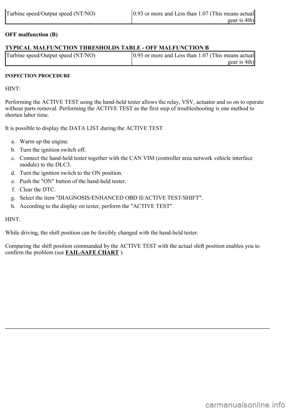
OFF malfunction (B)
TYPICAL MALFUNCTION THRESHOLDS TABLE - OFF MALFUNCTION B
INSPECTION PROCEDURE
HINT:
Performing the ACTIVE TEST using the hand-held tester allows the relay, VSV, actuator and so on to operate
without parts removal. Performing the ACTIVE TEST as the first step of troubleshooting is one method to
shorten labor time.
It is possible to display the DATA LIST during the ACTIVE TEST
a. Warm up the engine.
b. Turn the ignition switch off.
c. Connect the hand-held tester together with the CAN VIM (controller area network vehicle interface
module) to the DLC3.
d. Turn the ignition switch to the ON position.
e. Push the "ON" button of the hand-held tester.
f. Clear the DTC.
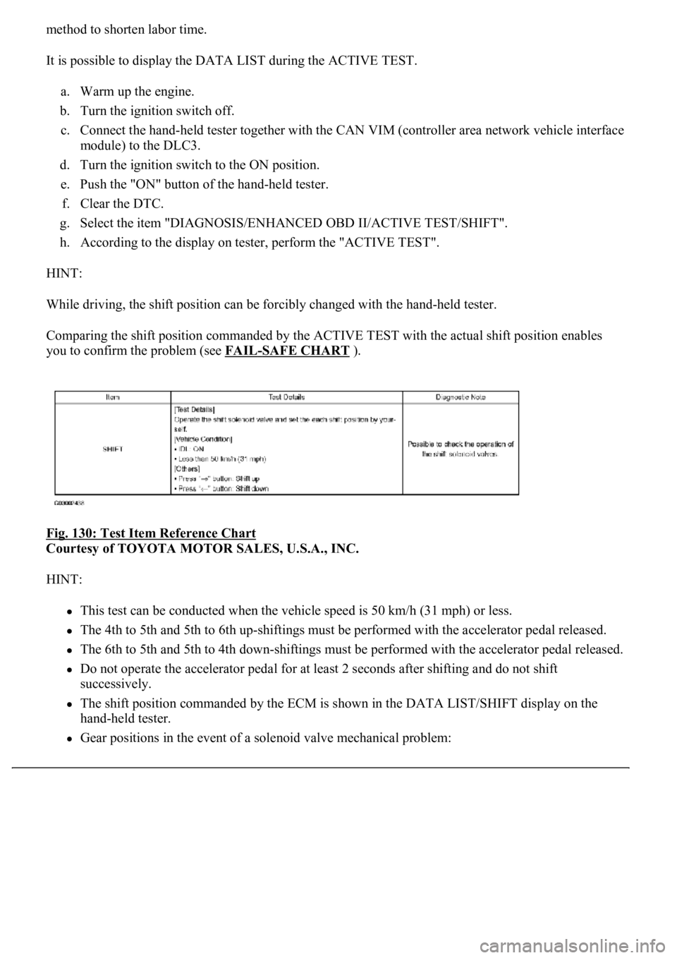
g. Select the item "DIAGNOSIS/ENHANCED OBD II/ACTIVE TEST/SHIFT".
h. According to the display on tester, perform the "ACTIVE TEST".
HINT:
While driving, the shift position can be forcibly changed with the hand-held tester.
Comparing the shift position commanded by the ACTIVE TEST with the actual shift position enables you to
confirm the problem (see FAIL
-SAFE CHART).
Turbine speed/Output speed (NT/NO)<00130011001c00160003005200550003005000520055004800030044005100470003002f00480056005600030057004b004400510003001400110013001a0003000b0037004b004c0056000300500048004400510056000300440046005700580044004f00
03[
gear is 4th)
Turbine speed/Output speed (NT/NO)<00130011001c00160003005200550003005000520055004800030044005100470003002f00480056005600030057004b004400510003001400110013001a0003000b0037004b004c0056000300500048004400510056000300440046005700580044004f00
03[
gear is 4th)
Page 2823 of 4500

method to shorten labor time.
It is possible to display the DATA LIST during the ACTIVE TEST.
a. Warm up the engine.
b. Turn the ignition switch off.
c. Connect the hand-held tester together with the CAN VIM (controller area network vehicle interface
module) to the DLC3.
d. Turn the ignition switch to the ON position.
e. Push the "ON" button of the hand-held tester.
f. Clear the DTC.
g. Select the item "DIAGNOSIS/ENHANCED OBD II/ACTIVE TEST/SHIFT".
h. According to the display on tester, perform the "ACTIVE TEST".
HINT:
While driving, the shift position can be forcibly changed with the hand-held tester.
Comparing the shift position commanded by the ACTIVE TEST with the actual shift position enables
you to confirm the problem (see FAIL
-SAFE CHART ).
Fig. 130: Test Item Reference Chart
Courtesy of TOYOTA MOTOR SALES, U.S.A., INC.
HINT:
This test can be conducted when the vehicle speed is 50 km/h (31 mph) or less.
The 4th to 5th and 5th to 6th up-shiftings must be performed with the accelerator pedal released.
The 6th to 5th and 5th to 4th down-shiftings must be performed with the accelerator pedal released.
Do not operate the accelerator pedal for at least 2 seconds after shifting and do not shift
successively.
The shift position commanded by the ECM is shown in the DATA LIST/SHIFT display on the
hand-held tester.
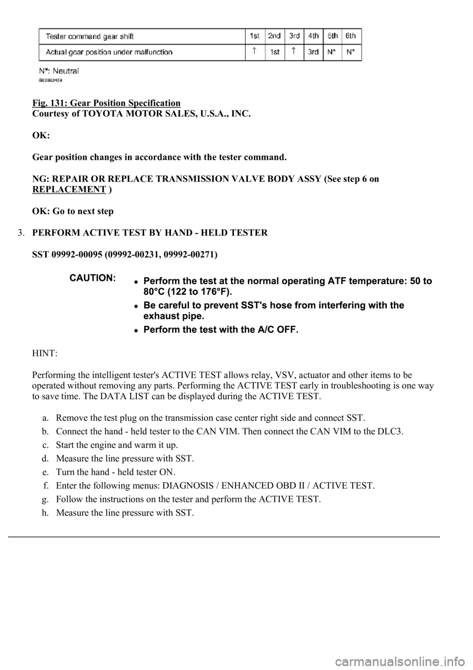
Gear positions in the event of a solenoid valve mechanical problem:
Page 2824 of 4500

Fig. 131: Gear Position Specification
Courtesy of TOYOTA MOTOR SALES, U.S.A., INC.
OK:
Gear position changes in accordance with the tester command.
NG: REPAIR OR REPLACE TRANSMISSION VALVE BODY ASSY (See step 6 on
REPLACEMENT
)
OK: Go to next step
3.PERFORM ACTIVE TEST BY HAND - HELD TESTER
SST 09992-00095 (09992-00231, 09992-00271)
HINT:
Performing the intelligent tester's ACTIVE TEST allows relay, VSV, actuator and other items to be
operated without removing any parts. Performing the ACTIVE TEST early in troubleshooting is one way
to save time. The DATA LIST can be displayed during the ACTIVE TEST.
a. Remove the test plug on the transmission case center right side and connect SST.
b. Connect the hand - held tester to the CAN VIM. Then connect the CAN VIM to the DLC3.
c. Start the engine and warm it up.
d. Measure the line pressure with SST.
e. Turn the hand - held tester ON.
f. Enter the following menus: DIAGNOSIS / ENHANCED OBD II / ACTIVE TEST.
g. Follow the instructions on the tester and perform the ACTIVE TEST.
h. Measure the line pressure with SST.
Page 2912 of 4500
c. Warm up the heated oxygen sensor with the engine speed at 2,500 rpm for approximately 2
minutes.
d. Check that the voltage changes between 0 and 1 V with the engine speed at 2,500 rpm.
OK: The voltage has changed more than 8 times in 10 seconds.
Fig. 6: Inspecting A/F Compensation System
Courtesy of TOYOTA MOTOR SALES, U.S.A., INC.
2.INSPECT FUEL CUT OFF RPM
a. Increase the engine speed to at least 3,000 rpm.
b. Use a sound scope to check the injector operation noise.
OK: When the throttle lever is released, the injector operation noise stops momentarily but
starts again soon after.
Page 3916 of 4500

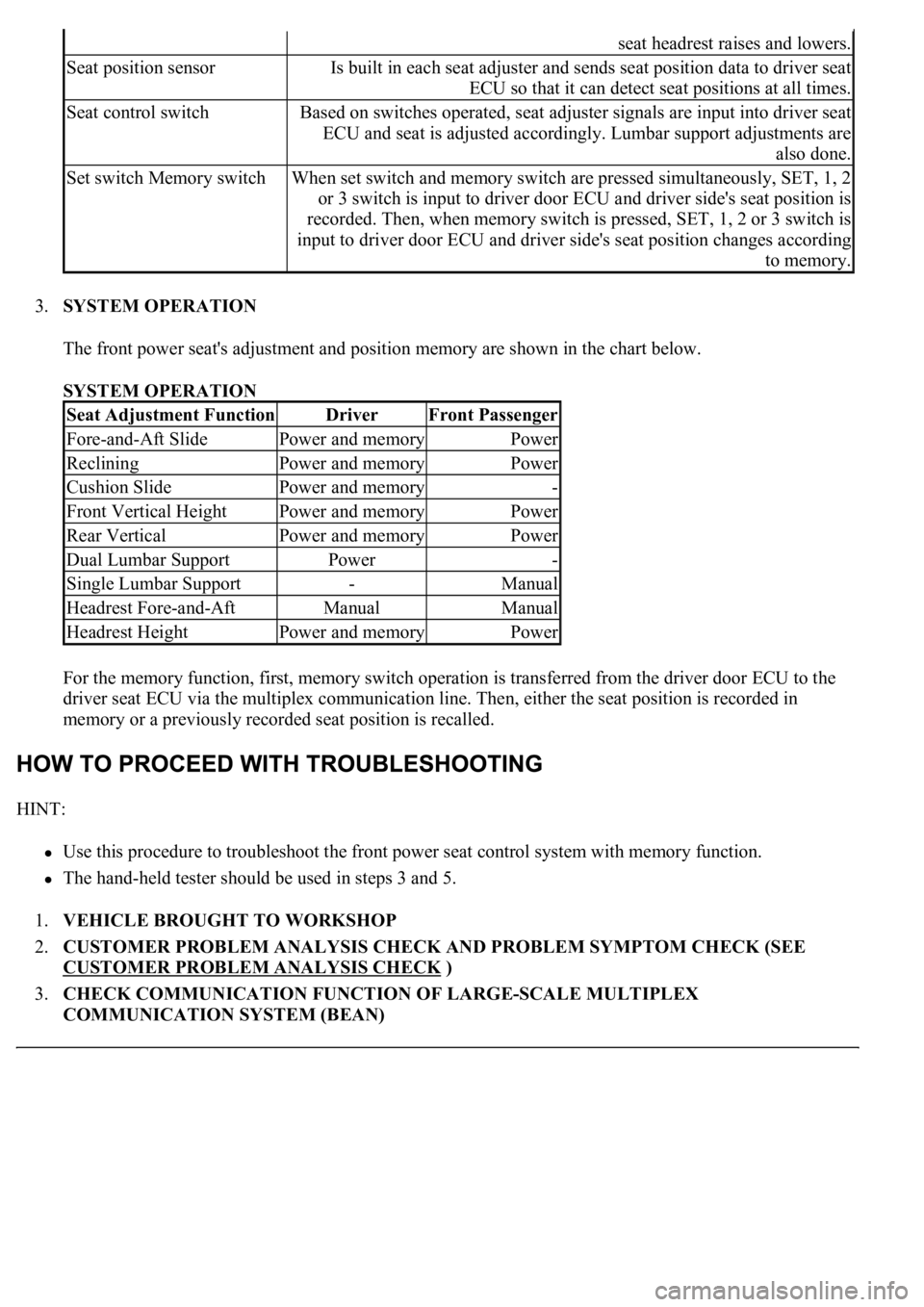
3.SYSTEM OPERATION
The front power seat's adjustment and position memory are shown in the chart below.
SYSTEM OPERATION
For the memory function, first, memory switch operation is transferred from the driver door ECU to the
driver seat ECU via the multiplex communication line. Then, either the seat position is recorded in
memory or a previously recorded seat position is recalled.
HINT:
Use this procedure to troubleshoot the front power seat control system with memory function.
<0037004b00480003004b0044005100470010004b0048004f0047000300570048005600570048005500030056004b00520058004f0047000300450048000300580056004800470003004c005100030056005700480053005600030016000300440051004700
030018001100030003[
1.VEHICLE BROUGHT TO WORKSHOP
2.CUSTOMER PROBLEM ANALYSIS CHECK AND PROBLEM SYMPTOM CHECK (SEE
CUSTOMER PROBLEM ANALYSIS CHECK
)
3.CHECK COMMUNICATION FUNCTION OF LARGE-SCALE MULTIPLEX
COMMUNICATION SYSTEM (BEAN)
seat headrest raises and lowers.
Seat position sensorIs built in each seat adjuster and sends seat position data to driver seat
ECU so that it can detect seat positions at all times.
Seat control switchBased on switches operated, seat adjuster signals are input into driver seat
ECU and seat is adjusted accordingly. Lumbar support adjustments are
also done.
Set switch Memory switchWhen set switch and memory switch are pressed simultaneously, SET, 1, 2
or 3 switch is input to driver door ECU and driver side's seat position is
recorded. Then, when memory switch is pressed, SET, 1, 2 or 3 switch is
input to driver door ECU and driver side's seat position changes according
to memory.
Seat Adjustment FunctionDriverFront Passenger
Fore-and-Aft SlidePower and memoryPower
RecliningPower and memoryPower
Cushion SlidePower and memory-
Front Vertical HeightPower and memoryPower
Rear VerticalPower and memoryPower
Dual Lumbar SupportPower-
Single Lumbar Support-Manual
Headrest Fore-and-AftManualManual
Headrest HeightPower and memoryPower
Page 4448 of 4500
Fig. 8: Identifying Multi-Display Outline
Courtesy of TOYOTA MOTOR SALES, U.S.A., INC.
4.AVC-LAN Description
a. What is AVC-LAN?
AVC-LAN, an abbreviation for "Audio Visual Communication Local Area Network", is a united
standard developed by the manufacturers in affiliation with Toyota Motor Corporation. This
standard pertains to audio and visual signals as well as switch and communication signals.
Fig. 9: Identifying Avc
-Lan System
Courtesy of TOYOTA MOTOR SALES, U.S.A., INC.
b. Purpose:
Recently, car audio systems have rapidly developed and the functions vastly changed. The
conventional car audio system is being integrated with multi-media interfaces similar to those in
navigation systems. At the same time, customers are demanding higher quality from their audio
s
ystems. This is merely an overview of the standardization background. The specific purposes are
Page 4489 of 4500
c. Vehicle Signal Check Screen
Fig. 50: Vehicle Signal Check Screen
Courtesy of TOYOTA MOTOR SALES, U.S.A., INC.
Vehicle signal
DISPLAY CHART
Sensor signal
DISPLAY CHART
HINT:
Signals are updated once per second only when vehicle sensor signals are changed.
DateThe date/time information obtained from GPS signal is displayed in Greenwich mean time
(GMT). The last 4 digits are displayed.
DisplayContents
REV/*1REV signal ON/OFF state is displayed.
SPD/*2SPD signal condition is displayed.
DisplayContents
Gyro
sensor/*3Gyro sensor output condition is displayed (when the vehicle runs straight or is
stationary, the voltage is approximately 2.5 V).