2003 JEEP GRAND CHEROKEE coil
[x] Cancel search: coilPage 5 of 2199

FASTENER USAGE
DESCRIPTION - FASTENER USAGE
WARNING: USE OF AN INCORRECT FASTENER
MAY RESULT IN COMPONENT DAMAGE OR PER-
SONAL INJURY.
Fasteners and torque specifications references in
this Service Manual are identified in metric and SAE
format.
During any maintenance or repair procedures, it is
important to salvage all fasteners (nuts, bolts, etc.)
for reassembly. If the fastener is not salvageable, a
fastener of equivalent specification must be used.
THREADED HOLE REPAIR
DESCRIPTION - THREADED HOLE REPAIR
Most stripped threaded holes can be repaired using
a Helicoilt. Follow the vehicle or Helicoiltrecommen-
dations for application and repair procedures.
INTERNATIONAL SYMBOLS
DESCRIPTION - INTERNATIONAL SYMBOLS
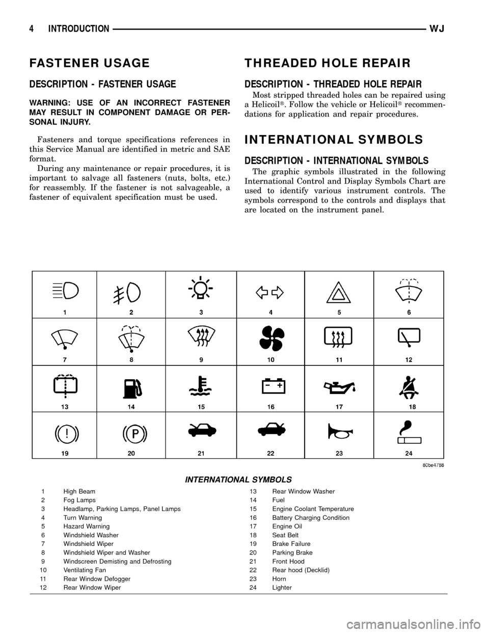
The graphic symbols illustrated in the following
International Control and Display Symbols Chart are
used to identify various instrument controls. The
symbols correspond to the controls and displays that
are located on the instrument panel.
INTERNATIONAL SYMBOLS
1 High Beam 13 Rear Window Washer
2 Fog Lamps 14 Fuel
3 Headlamp, Parking Lamps, Panel Lamps 15 Engine Coolant Temperature
4 Turn Warning 16 Battery Charging Condition
5 Hazard Warning 17 Engine Oil
6 Windshield Washer 18 Seat Belt
7 Windshield Wiper 19 Brake Failure
8 Windshield Wiper and Washer 20 Parking Brake
9 Windscreen Demisting and Defrosting 21 Front Hood
10 Ventilating Fan 22 Rear hood (Decklid)
11 Rear Window Defogger 23 Horn
12 Rear Window Wiper 24 Lighter
4 INTRODUCTIONWJ
Page 27 of 2199

FRONT
TABLE OF CONTENTS
page page
FRONT
DESCRIPTION..........................6
STANDARD PROCEDURE - SERVICE
WARNINGS AND CAUTIONS..............6
SPECIFICATIONS
TORQUE CHART......................7
SPECIAL TOOLS
FRONT SUSPENSION...................8
BUSHINGS
REMOVAL.............................9
INSTALLATION..........................9
HUB / BEARING
DESCRIPTION..........................9
OPERATION............................9
REMOVAL.............................9
INSTALLATION.........................10
KNUCKLE
DESCRIPTION.........................10
OPERATION...........................10
REMOVAL - STEERING KNUCKLE..........10
INSTALLATION.........................10
LOWER BALL JOINT
REMOVAL.............................11
LOWER CONTROL ARM
DESCRIPTION.........................11
OPERATION...........................11
REMOVAL.............................11
INSTALLATION.........................11SHOCK
DESCRIPTION.........................12
OPERATION...........................12
REMOVAL.............................12
INSTALLATION.........................12
SPRING
DESCRIPTION.........................12
OPERATION...........................13
REMOVAL.............................13
INSTALLATION.........................13
STABILIZER BAR
DESCRIPTION.........................14
OPERATION...........................14
REMOVAL.............................14
INSTALLATION.........................14
TRACK BAR
DESCRIPTION.........................14
OPERATION...........................14
REMOVAL.............................14
INSTALLATION.........................14
UPPER BALL JOINT
REMOVAL.............................15
UPPER CONTROL ARM
DESCRIPTION.........................16
OPERATION...........................16
REMOVAL.............................16
INSTALLATION.........................16
FRONT
DESCRIPTION
The front suspension (Fig. 1) is a link/coil design
comprised of :
²Drive axle
²Shock absorbers
²Coil springs
²Upper and lower suspension arms
²Stabilizer bar
²Track bar
²Jounce bumpers
CAUTION: Components attached with a nut and cot-
ter pin must be torqued to specification. Then if the
slot in the nut does not line up with the cotter pin
hole, tighten nut until it is aligned. Never loosen the
nut to align the cotter pin hole.CAUTION: Suspension components with rubber
bushings must be tightened with the vehicle at nor-
mal ride height. It is important to have the springs
supporting the weight of the vehicle when the fas-
teners are torqued. If springs are not at their normal
ride position, vehicle ride comfort will be affected
and cause premature bushing wear.
STANDARD PROCEDURE - SERVICE
WARNINGS AND CAUTIONS
CAUTION: Suspension components with rubber
bushings must be tightened with the vehicle at nor-
mal ride height. It is important to have the springs
supporting the weight of the vehicle when the fas-
teners are torqued. If springs are not at their normal
ride position, vehicle ride comfort will be affected
and cause premature bushing wear.
2 - 6 FRONTWJ
Page 28 of 2199

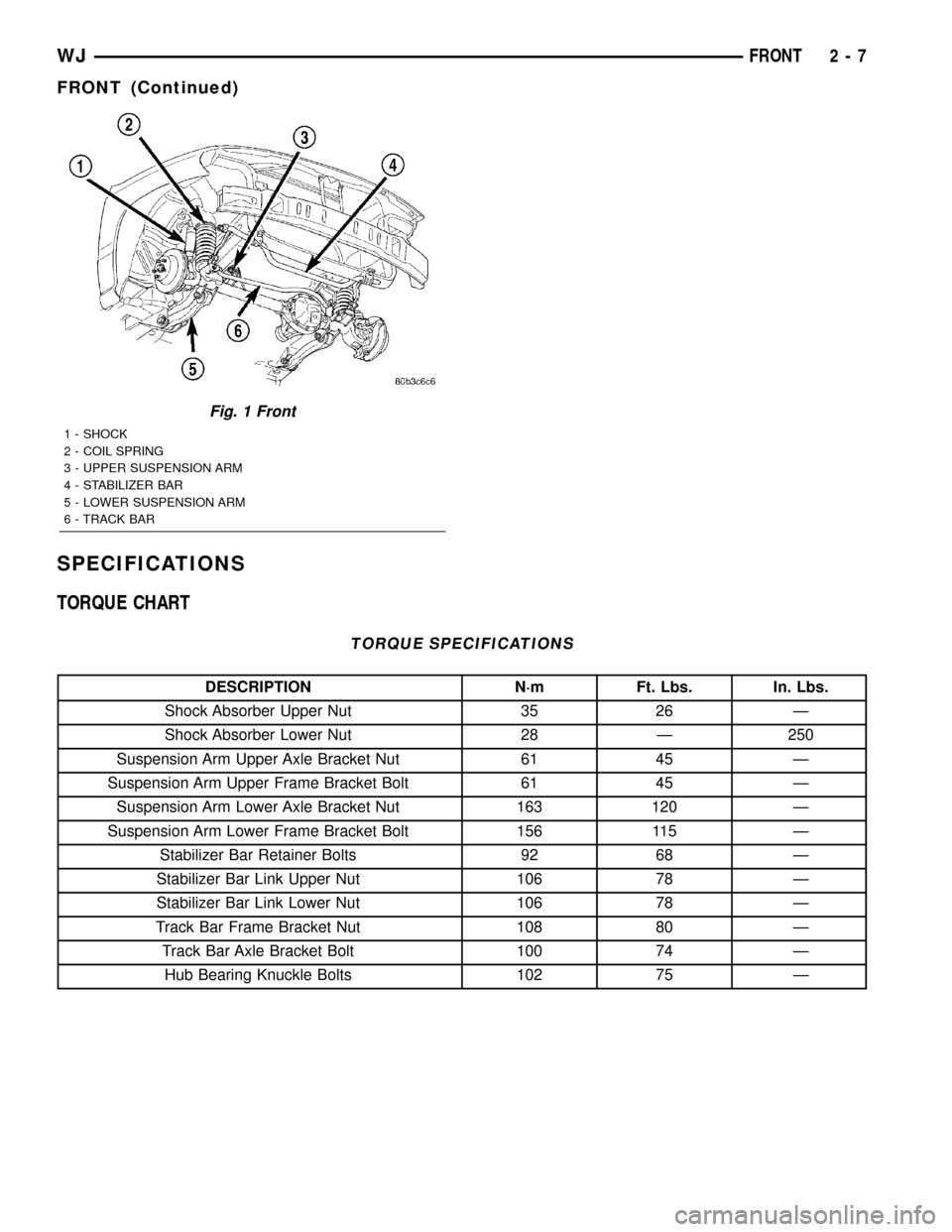
SPECIFICATIONS
TORQUE CHART
TORQUE SPECIFICATIONS
DESCRIPTION N´m Ft. Lbs. In. Lbs.
Shock Absorber Upper Nut 35 26 Ð
Shock Absorber Lower Nut 28 Ð 250
Suspension Arm Upper Axle Bracket Nut 61 45 Ð
Suspension Arm Upper Frame Bracket Bolt 61 45 Ð
Suspension Arm Lower Axle Bracket Nut 163 120 Ð
Suspension Arm Lower Frame Bracket Bolt 156 115 Ð
Stabilizer Bar Retainer Bolts 92 68 Ð
Stabilizer Bar Link Upper Nut 106 78 Ð
Stabilizer Bar Link Lower Nut 106 78 Ð
Track Bar Frame Bracket Nut 108 80 Ð
Track Bar Axle Bracket Bolt 100 74 Ð
Hub Bearing Knuckle Bolts 102 75 Ð
Fig. 1 Front
1 - SHOCK
2 - COIL SPRING
3 - UPPER SUSPENSION ARM
4 - STABILIZER BAR
5 - LOWER SUSPENSION ARM
6 - TRACK BAR
WJFRONT 2 - 7
FRONT (Continued)
Page 33 of 2199

SHOCK
DESCRIPTION
The top of the shock absorbers are bolted to the
body. The bottom of the shocks are bolted to the axle
brackets. The standard shocks have conventional
twin tube construction and are low pressure gas
charged. Gas charging prevents cavitation during
rough road operation. Up-Country shocks are mono
tube design and are high pressure gas charged.
OPERATION
The shock absorbers dampen jounce and rebound
motion of the vehicle over various road conditions
and limit suspension rebound travel.
REMOVAL
(1) Remove the nut, retainer and grommet from
the shock stud in the engine compartment (Fig. 8).
(2) Raise and support the front axle.
(3) Remove the lower mounting nuts from the axle
bracket (Fig. 9). Remove the shock absorber.
INSTALLATION
(1) Position the lower retainer and grommet on the
shock stud. Insert the shock absorber through the
shock tower hole.
(2) Install the lower shock studs into the axle
bracket.
(3) Install the mounting nuts and tighten to 28
N´m (250 in. lbs.).
(4) Remove support and lower the vehicle.(5) Install the upper grommet, retainer and nut on
the stud in the engine compartment. Hold the shock
stud witha8mmwrench and tighten the nut to 35
N´m (26 ft. lbs.).SPRING
DESCRIPTION
The coil springs mount up in the wheelhouse which
is part of the unitized body bracket. A rubber dough-
nut isolator is located between the top of the spring
and the body. The bottom of the spring seats on a
axle isolator made of rubber with a steel insert.
Fig. 7 Lower Suspension Arm
1 - LOWER SUSPENSION ARM
2 - FRAME RAIL BRACKET
3 - AXLE BRACKET
Fig. 8 Upper Shock Mounting
1 - RETAINER
2 - STUD
3 - NUT
4 - GROMMET
Fig. 9 Lower Shock Mounting
1 - SHOCK ABSORBER
2 - MOUNTING NUTS
2 - 12 FRONTWJ
LOWER CONTROL ARM (Continued)
Page 34 of 2199

OPERATION
The coil springs control ride quality and maintain
proper ride height. The isolators provide road noise
isolation.
REMOVAL
(1) Raise and support the vehicle.
(2) Remove the wheel and tire assemblies.
(3) Position a hydraulic jack under the axle to sup-
port it.
(4) Remove shock absorbers lower mounting nuts
from the axle brackets.
(5) Remove the track bar mounting bolt from the
axle bracket.
NOTE: Make sure the lower part of the shock does
not hold tension on the brake lines at the axle tube
housing located at the lower shock mounting area.
(6) Lower the axle until the spring is free from the
upper mount and isolator (Fig. 10).
(7) Remove the spring from the vehicle.
(8) Remove and inspect the upper and lower
spring isolators.
INSTALLATION
(1) Install the upper isolator.
(2) Install the lower isolator with the isolator loca-
tor nub in the axle pad hole (Fig. 11).
(3) Position the coil spring on the axle spring pad.CAUTION: Ensure the spring is positioned on the
lower isolator with the end of the spring coil
against the isolator spring locator (Fig. 12).
(4) Raise the axle and guide the springs onto the
spring upper mounts and lower shock studs into the
axle brackets.
(5) Install the shock absorbers lower mounting
nuts.
Fig. 10 Front Coil Spring
1 - UPPER ISOLATOR
2 - COIL SPRING
3 - LOWER ISOLATOR
4 - STABILIZER LINK
Fig. 11 Lower Isolator
1 - LOCATING NUB
2 - LOWER ISOLATOR
3 - AXLE SPRING PAD
4 - LOCATING HOLE
Fig. 12 Isolator Spring Locator
1 - COIL SPRING
2 - SPRING LOCATOR
3 - LOWER ISOLATOR
WJFRONT 2 - 13
SPRING (Continued)
Page 38 of 2199

REAR
TABLE OF CONTENTS
page page
REAR
DESCRIPTION.........................17
WARNING.............................17
DIAGNOSIS AND TESTING - REAR
SUSPENSION........................18
SPECIFICATIONS
TORQUE CHART......................18
SPECIAL TOOLS
REAR SUSPENSION...................19
LOWER CONTROL ARM
DESCRIPTION.........................19
OPERATION...........................19
REMOVAL.............................19
INSTALLATION.........................19
SHOCK
DESCRIPTION.........................19
OPERATION...........................19
REMOVAL.............................19
INSTALLATION.........................19
SPRING
DESCRIPTION.........................20OPERATION...........................20
REMOVAL.............................20
INSTALLATION.........................20
STABILIZER BAR
DESCRIPTION.........................21
OPERATION...........................21
REMOVAL.............................21
INSTALLATION.........................21
UPPER BALL JOINT
DESCRIPTION - UPPER SUSPENSION ARM,
BUSHINGS, AND BALL JOINT............21
OPERATION - UPPER SUSPENSION ARM,
BUSHINGS, AND BALL JOINT............21
REMOVAL.............................21
INSTALLATION.........................22
UPPER CONTROL ARM
DESCRIPTION.........................22
OPERATION...........................22
REMOVAL.............................22
INSTALLATION.........................23
REAR
DESCRIPTION
The rear suspension (Fig. 1) is comprised of :
²Drive axle
²Shock absorbers
²Coil springs
²Lower suspension arms
²Upper suspension arm
²Stabilizer bar
CAUTION: Suspension components with rubber/ure-
thane bushings should be tightened with the vehi-
cle at normal ride height. It is important to have the
springs supporting the weight of the vehicle when
the fasteners are torqued. This will maintain vehicle
ride comfort and prevent premature bushing wear.
WARNING
WARNING:: Suspension components with rubber
bushings must be tightened with the vehicle at nor-
mal ride height. It is important to have the springs
supporting the weight of the vehicle when the fas-
teners are torqued. If springs are not at their normalride position, vehicle ride comfort will be affected
and cause premature bushing wear.
Fig. 1 Rear Suspension
1 - SHOCK
2 - UPPER SUSPENSION ARM
3 - COIL SPRING
4 - STABILIZER BAR
5 - LOWER SUSPENSION ARM
WJREAR 2 - 17
Page 41 of 2199

SPRING
DESCRIPTION
The coil springs mount up in the wheelhouse which
is part of the unitized body bracket. A rubber dough-
nut isolator is located between the top of the spring
and the body. The bottom of the spring seats on a
axle isolator made of rubber with a steel insert. The
isolators provide road noise isolation
OPERATION
The coil springs control ride quality and maintain
proper ride height.
REMOVAL
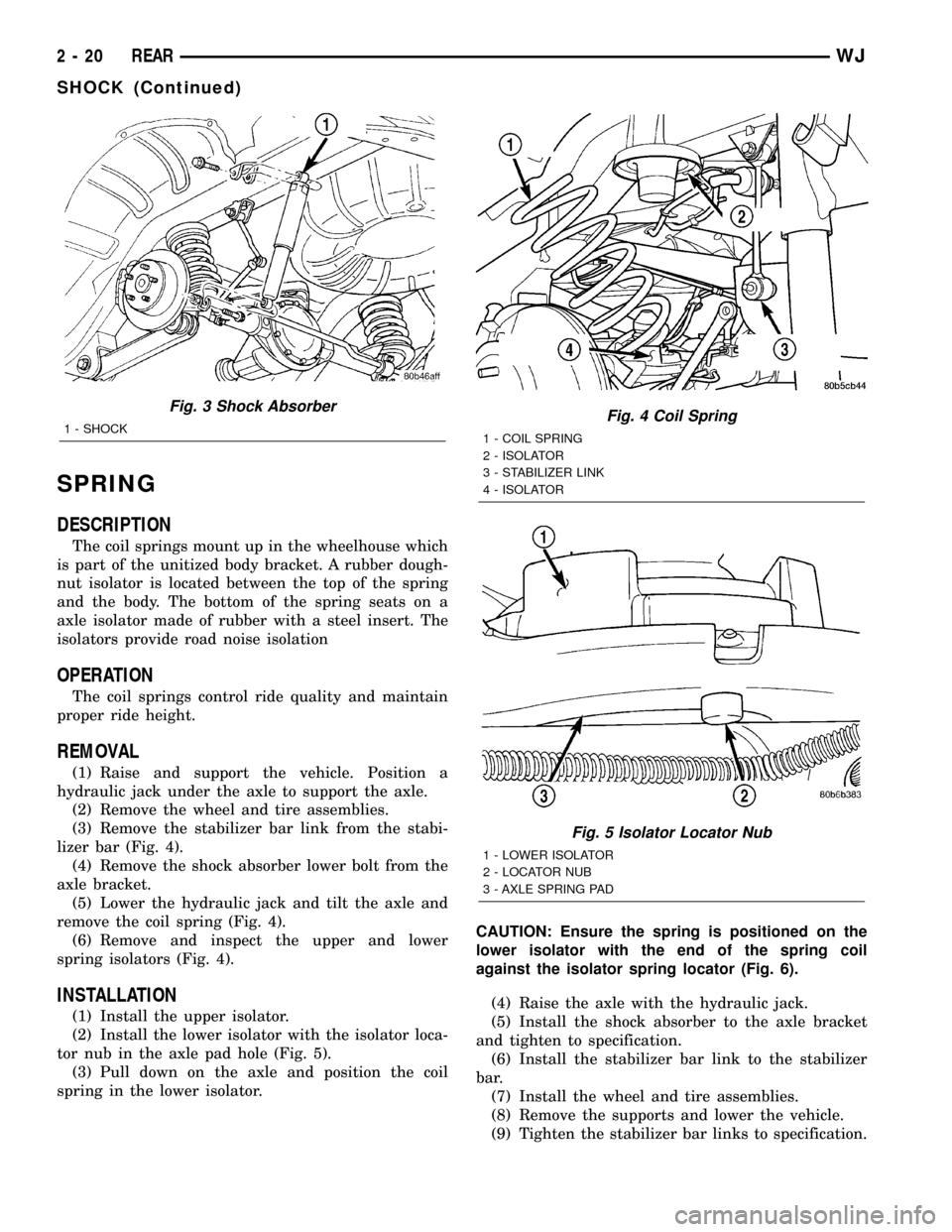
(1) Raise and support the vehicle. Position a
hydraulic jack under the axle to support the axle.
(2) Remove the wheel and tire assemblies.
(3) Remove the stabilizer bar link from the stabi-
lizer bar (Fig. 4).
(4) Remove the shock absorber lower bolt from the
axle bracket.
(5) Lower the hydraulic jack and tilt the axle and
remove the coil spring (Fig. 4).
(6) Remove and inspect the upper and lower
spring isolators (Fig. 4).
INSTALLATION
(1) Install the upper isolator.
(2) Install the lower isolator with the isolator loca-
tor nub in the axle pad hole (Fig. 5).
(3) Pull down on the axle and position the coil
spring in the lower isolator.CAUTION: Ensure the spring is positioned on the
lower isolator with the end of the spring coil
against the isolator spring locator (Fig. 6).
(4) Raise the axle with the hydraulic jack.
(5) Install the shock absorber to the axle bracket
and tighten to specification.
(6) Install the stabilizer bar link to the stabilizer
bar.
(7) Install the wheel and tire assemblies.
(8) Remove the supports and lower the vehicle.
(9) Tighten the stabilizer bar links to specification.
Fig. 3 Shock Absorber
1 - SHOCKFig. 4 Coil Spring
1 - COIL SPRING
2 - ISOLATOR
3 - STABILIZER LINK
4 - ISOLATOR
Fig. 5 Isolator Locator Nub
1 - LOWER ISOLATOR
2 - LOCATOR NUB
3 - AXLE SPRING PAD
2 - 20 REARWJ
SHOCK (Continued)
Page 42 of 2199

STABILIZER BAR
DESCRIPTION
The stabilizer bar extends across the back side of
the rear axle. Links are connected between the bar
and frame rail brackets. The stabilizer bar and links
are isolated by rubber bushings.
OPERATION
The stabilizer bar is used to control vehicle body
roll, during turns. The bar helps control the vehicle
body in relationship to the suspension.
REMOVAL
(1) Raise and support the vehicle.
(2) Remove the stabilizer bar links from stabilizer
bar and frame mount. (Fig. 7).
(3) Remove the stabilizer bar retainer bolts.
(4) Remove the stabilizer bar.
INSTALLATION
(1) Position the stabilizer bar on the axle and
install the retainers and bolts. Ensure the bar is cen-
tered with equal spacing on both sides. Tighten the
bolts to 54 N´m (40 ft. lbs.).
(2) Install the links to the stabilizer bar and frame
brackets.
(3) Tighten the nuts at the stabilizer bar to 54
N´m (40 ft. lbs.).
(4) Tighten the nuts at the frame brackets to 92
N´m (68 ft. lbs.).
(5) Remove support and lower the vehicle.
UPPER BALL JOINT
DESCRIPTION - UPPER SUSPENSION ARM,
BUSHINGS, AND BALL JOINT
The suspension arm uses vertical spool bushings to
isolate road noise. The suspension arm is bolted
through bushings to cage nuts in the body and a ball
joint plate to the top of the differential housing.
OPERATION - UPPER SUSPENSION ARM,
BUSHINGS, AND BALL JOINT
The upper suspension arm provides fore/aft and
lateral location of the rear axle. The suspension arm
travel is limited through the use of jounce bumpers
in compression and shock absorbers in rebound.
REMOVAL
(1) Raise and support the vehicle.
(2) Support the rear axle with a hydraulic jack.
(3) Remove the ball joint nut from the top of the
upper suspension arm (Fig. 8).
(4) Separate ball joint from the arm with Remover
8278 (Fig. 9).
NOTE: It may be necessary to strike the upper con-
trol arm with a hammer to separate the ball joint
from the arm.
(5) Remove the ball joint mounting bolts (Fig.
10)from the differential housing.
(6) Remove the ball joint from the differential
housing.
Fig. 6 Isolator Spring Locator - Typical
1 - LOWER ISOLATOR
2 - SPRING LOCATOR
3 - COIL SPRING
Fig. 7 Rear Stabilizer Bar
1 - LINK
2 - RETAINER
3 - BUSHING
4 - STABILIZER BAR
WJREAR 2 - 21
SPRING (Continued)