2003 JEEP GRAND CHEROKEE Thrust plate
[x] Cancel search: Thrust platePage 125 of 2199
(2) Remove ring gear if the ring gear is to be
replaced. The Trac-loktdifferential can be serviced
with the ring gear installed.
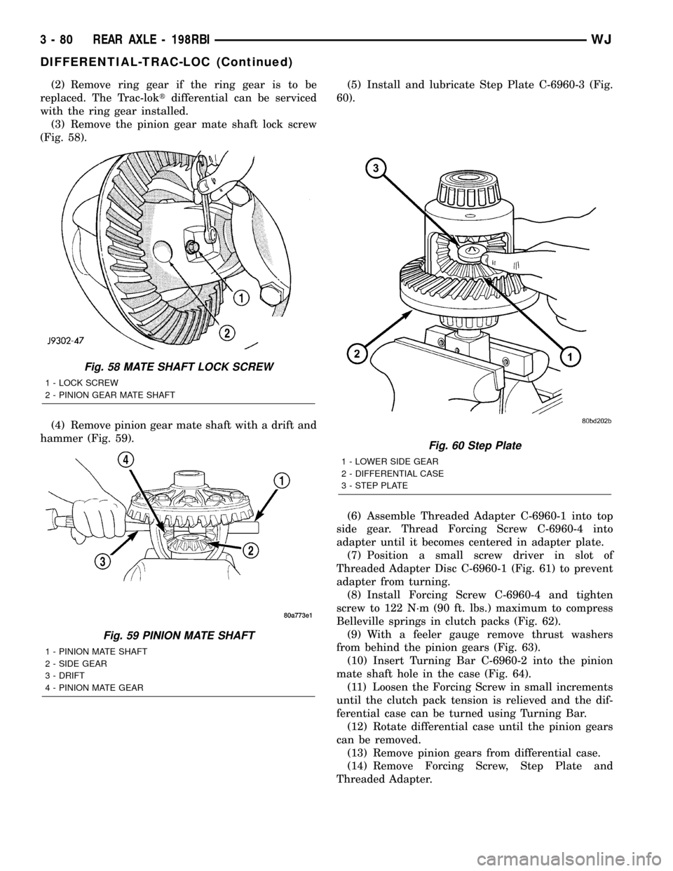
(3) Remove the pinion gear mate shaft lock screw
(Fig. 58).
(4) Remove pinion gear mate shaft with a drift and
hammer (Fig. 59).(5) Install and lubricate Step Plate C-6960-3 (Fig.
60).
(6) Assemble Threaded Adapter C-6960-1 into top
side gear. Thread Forcing Screw C-6960-4 into
adapter until it becomes centered in adapter plate.
(7) Position a small screw driver in slot of
Threaded Adapter Disc C-6960-1 (Fig. 61) to prevent
adapter from turning.
(8) Install Forcing Screw C-6960-4 and tighten
screw to 122 N´m (90 ft. lbs.) maximum to compress
Belleville springs in clutch packs (Fig. 62).
(9) With a feeler gauge remove thrust washers
from behind the pinion gears (Fig. 63).
(10) Insert Turning Bar C-6960-2 into the pinion
mate shaft hole in the case (Fig. 64).
(11) Loosen the Forcing Screw in small increments
until the clutch pack tension is relieved and the dif-
ferential case can be turned using Turning Bar.
(12) Rotate differential case until the pinion gears
can be removed.
(13) Remove pinion gears from differential case.
(14) Remove Forcing Screw, Step Plate and
Threaded Adapter.
Fig. 58 MATE SHAFT LOCK SCREW
1 - LOCK SCREW
2 - PINION GEAR MATE SHAFT
Fig. 59 PINION MATE SHAFT
1 - PINION MATE SHAFT
2 - SIDE GEAR
3 - DRIFT
4 - PINION MATE GEAR
Fig. 60 Step Plate
1 - LOWER SIDE GEAR
2 - DIFFERENTIAL CASE
3 - STEP PLATE
3 - 80 REAR AXLE - 198RBIWJ
DIFFERENTIAL-TRAC-LOC (Continued)
Page 126 of 2199
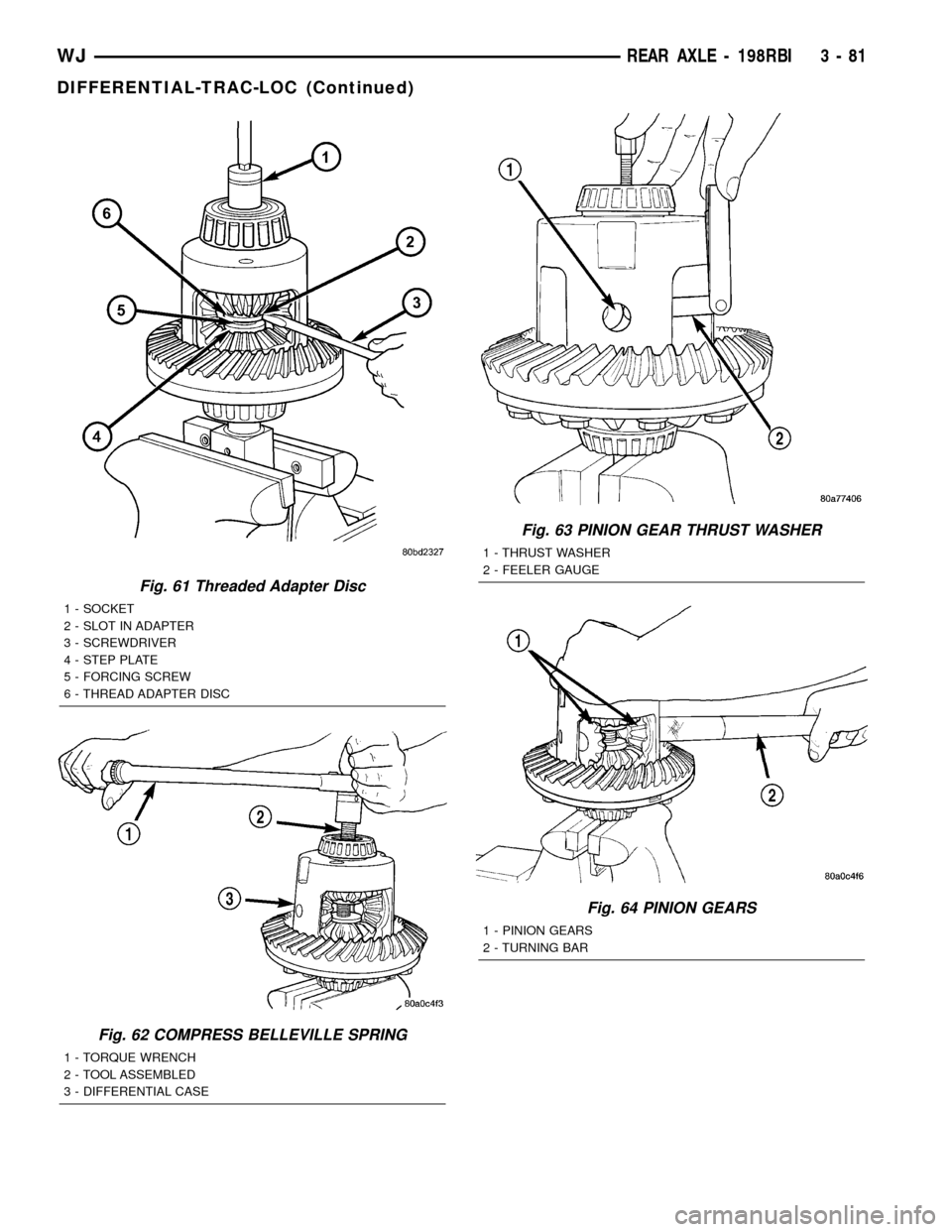
Fig. 61 Threaded Adapter Disc
1 - SOCKET
2 - SLOT IN ADAPTER
3 - SCREWDRIVER
4 - STEP PLATE
5 - FORCING SCREW
6 - THREAD ADAPTER DISC
Fig. 62 COMPRESS BELLEVILLE SPRING
1 - TORQUE WRENCH
2 - TOOL ASSEMBLED
3 - DIFFERENTIAL CASE
Fig. 63 PINION GEAR THRUST WASHER
1 - THRUST WASHER
2 - FEELER GAUGE
Fig. 64 PINION GEARS
1 - PINION GEARS
2 - TURNING BAR
WJREAR AXLE - 198RBI 3 - 81
DIFFERENTIAL-TRAC-LOC (Continued)
Page 128 of 2199

(5) Position the differential case on the Holding
Fixture 6965.
(6) Install lubricated Step Plate C-6960-3 in lower
side gear (Fig. 68).
(7) Install the upper side gear and clutch disc pack
(Fig. 68).
(8) Hold assembly in position. Insert Threaded
Adapter C-6960-1 into top side gear.
(9) Install Forcing Screw C-6960-4 and tighten
screw to slightly compress clutch disc.
(10) Place pinion gears in position in side gears
and verify that the pinion mate shaft hole is aligned.
(11) Rotate case with Turning Bar C-6960-2 until
the pinion mate shaft holes in pinion gears align
with holes in case. It may be necessary to slightly
tighten the forcing screw in order to install the pin-
ion gears.
(12) Tighten forcing screw to 122 N´m (90 ft. lbs.)
maximum to compress the Belleville springs.
(13) Lubricate and install thrust washers behind
pinion gears and align washers with a small screw
driver. Insert mate shaft into each pinion gear to ver-
ify alignment.
(14) Remove Forcing Screw, Step Plate and
Threaded Adapter.(15) Install pinion gear mate shaft and align holes
in shaft and case.
(16) Install pinion mate shaft lock screw finger
tight to hold shaft during differential installation.
(17) Lubricate all differential components with
hypoid gear lubricant.
DIFFERENTIAL CASE
BEARINGS
REMOVAL
(1) Raise and support vehicle.
(2) Remove differential case from axle housing.
(3) Remove bearings from the differential case
with Puller/Press C-293-PA, Adapter 8352 and Plug
SP-3289 (Fig. 69).
Fig. 68 CLUTCH PACK AND UPPER SIDE GEAR
1 - SIDE GEAR AND CLUTCH PACK
2 - DIFFERENTIAL CASE
3 - STEP PLATE
Fig. 69 Differential Bearing
1 - ADAPTERS
2 - BEARING
3 - DIFFERENTIAL
4 - PLUG
5 - PULLER
WJREAR AXLE - 198RBI 3 - 83
DIFFERENTIAL-TRAC-LOC (Continued)
Page 166 of 2199
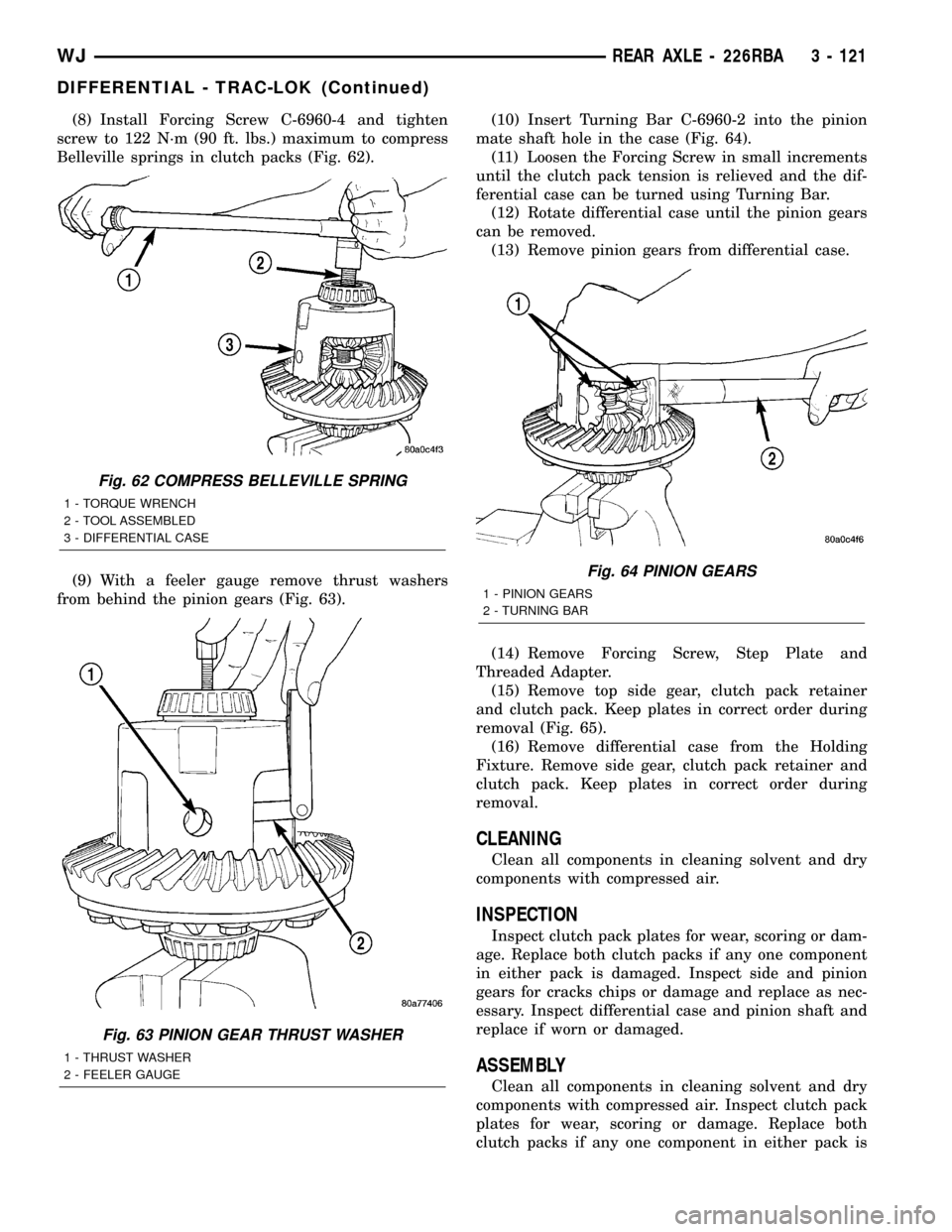
(8) Install Forcing Screw C-6960-4 and tighten
screw to 122 N´m (90 ft. lbs.) maximum to compress
Belleville springs in clutch packs (Fig. 62).
(9) With a feeler gauge remove thrust washers
from behind the pinion gears (Fig. 63).(10) Insert Turning Bar C-6960-2 into the pinion
mate shaft hole in the case (Fig. 64).
(11) Loosen the Forcing Screw in small increments
until the clutch pack tension is relieved and the dif-
ferential case can be turned using Turning Bar.
(12) Rotate differential case until the pinion gears
can be removed.
(13) Remove pinion gears from differential case.
(14) Remove Forcing Screw, Step Plate and
Threaded Adapter.
(15) Remove top side gear, clutch pack retainer
and clutch pack. Keep plates in correct order during
removal (Fig. 65).
(16) Remove differential case from the Holding
Fixture. Remove side gear, clutch pack retainer and
clutch pack. Keep plates in correct order during
removal.
CLEANING
Clean all components in cleaning solvent and dry
components with compressed air.
INSPECTION
Inspect clutch pack plates for wear, scoring or dam-
age. Replace both clutch packs if any one component
in either pack is damaged. Inspect side and pinion
gears for cracks chips or damage and replace as nec-
essary. Inspect differential case and pinion shaft and
replace if worn or damaged.
ASSEMBLY
Clean all components in cleaning solvent and dry
components with compressed air. Inspect clutch pack
plates for wear, scoring or damage. Replace both
clutch packs if any one component in either pack is
Fig. 62 COMPRESS BELLEVILLE SPRING
1 - TORQUE WRENCH
2 - TOOL ASSEMBLED
3 - DIFFERENTIAL CASE
Fig. 63 PINION GEAR THRUST WASHER
1 - THRUST WASHER
2 - FEELER GAUGE
Fig. 64 PINION GEARS
1 - PINION GEARS
2 - TURNING BAR
WJREAR AXLE - 226RBA 3 - 121
DIFFERENTIAL - TRAC-LOK (Continued)
Page 168 of 2199
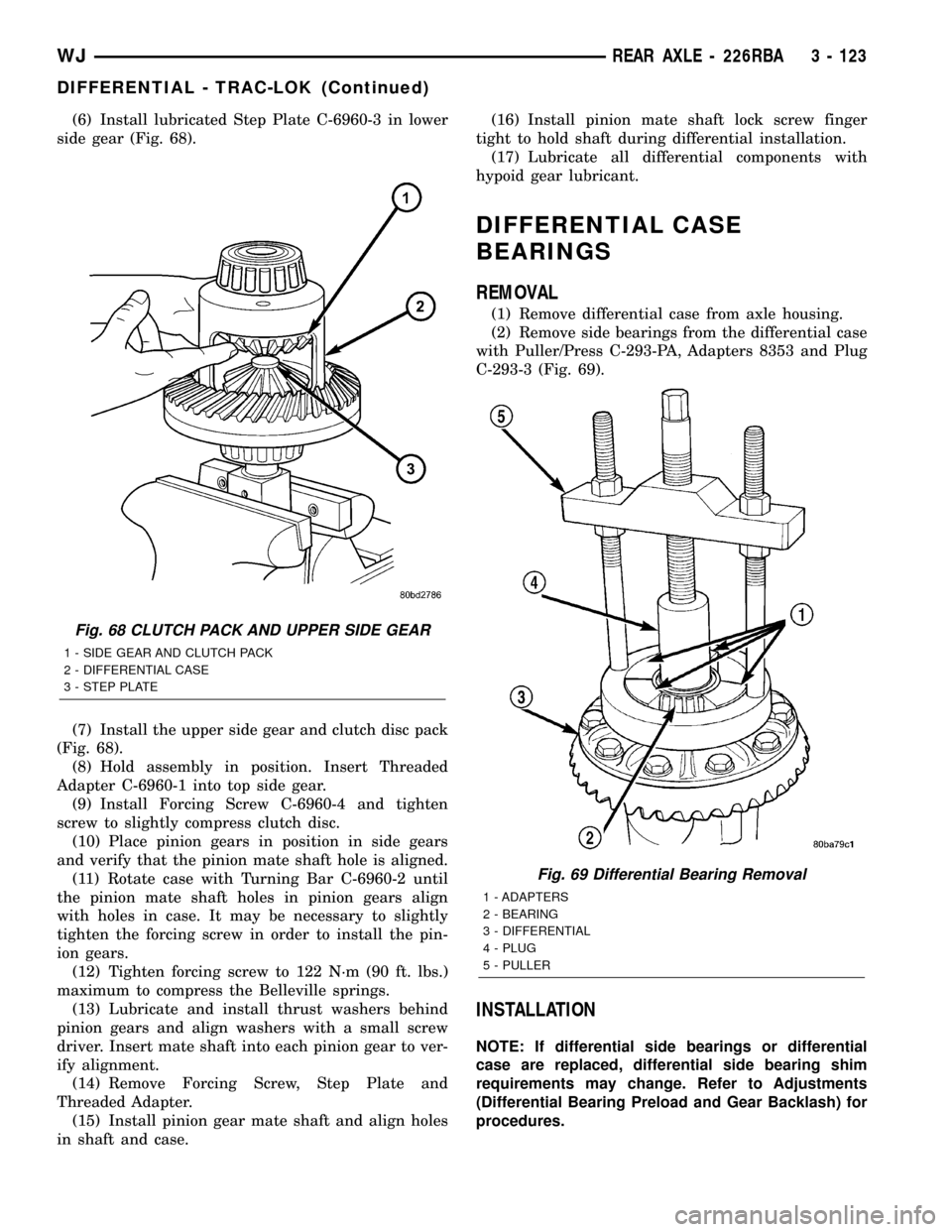
(6) Install lubricated Step Plate C-6960-3 in lower
side gear (Fig. 68).
(7) Install the upper side gear and clutch disc pack
(Fig. 68).
(8) Hold assembly in position. Insert Threaded
Adapter C-6960-1 into top side gear.
(9) Install Forcing Screw C-6960-4 and tighten
screw to slightly compress clutch disc.
(10) Place pinion gears in position in side gears
and verify that the pinion mate shaft hole is aligned.
(11) Rotate case with Turning Bar C-6960-2 until
the pinion mate shaft holes in pinion gears align
with holes in case. It may be necessary to slightly
tighten the forcing screw in order to install the pin-
ion gears.
(12) Tighten forcing screw to 122 N´m (90 ft. lbs.)
maximum to compress the Belleville springs.
(13) Lubricate and install thrust washers behind
pinion gears and align washers with a small screw
driver. Insert mate shaft into each pinion gear to ver-
ify alignment.
(14) Remove Forcing Screw, Step Plate and
Threaded Adapter.
(15) Install pinion gear mate shaft and align holes
in shaft and case.(16) Install pinion mate shaft lock screw finger
tight to hold shaft during differential installation.
(17) Lubricate all differential components with
hypoid gear lubricant.
DIFFERENTIAL CASE
BEARINGS
REMOVAL
(1) Remove differential case from axle housing.
(2) Remove side bearings from the differential case
with Puller/Press C-293-PA, Adapters 8353 and Plug
C-293-3 (Fig. 69).
INSTALLATION
NOTE: If differential side bearings or differential
case are replaced, differential side bearing shim
requirements may change. Refer to Adjustments
(Differential Bearing Preload and Gear Backlash) for
procedures.
Fig. 68 CLUTCH PACK AND UPPER SIDE GEAR
1 - SIDE GEAR AND CLUTCH PACK
2 - DIFFERENTIAL CASE
3 - STEP PLATE
Fig. 69 Differential Bearing Removal
1 - ADAPTERS
2 - BEARING
3 - DIFFERENTIAL
4 - PLUG
5 - PULLER
WJREAR AXLE - 226RBA 3 - 123
DIFFERENTIAL - TRAC-LOK (Continued)
Page 1250 of 2199
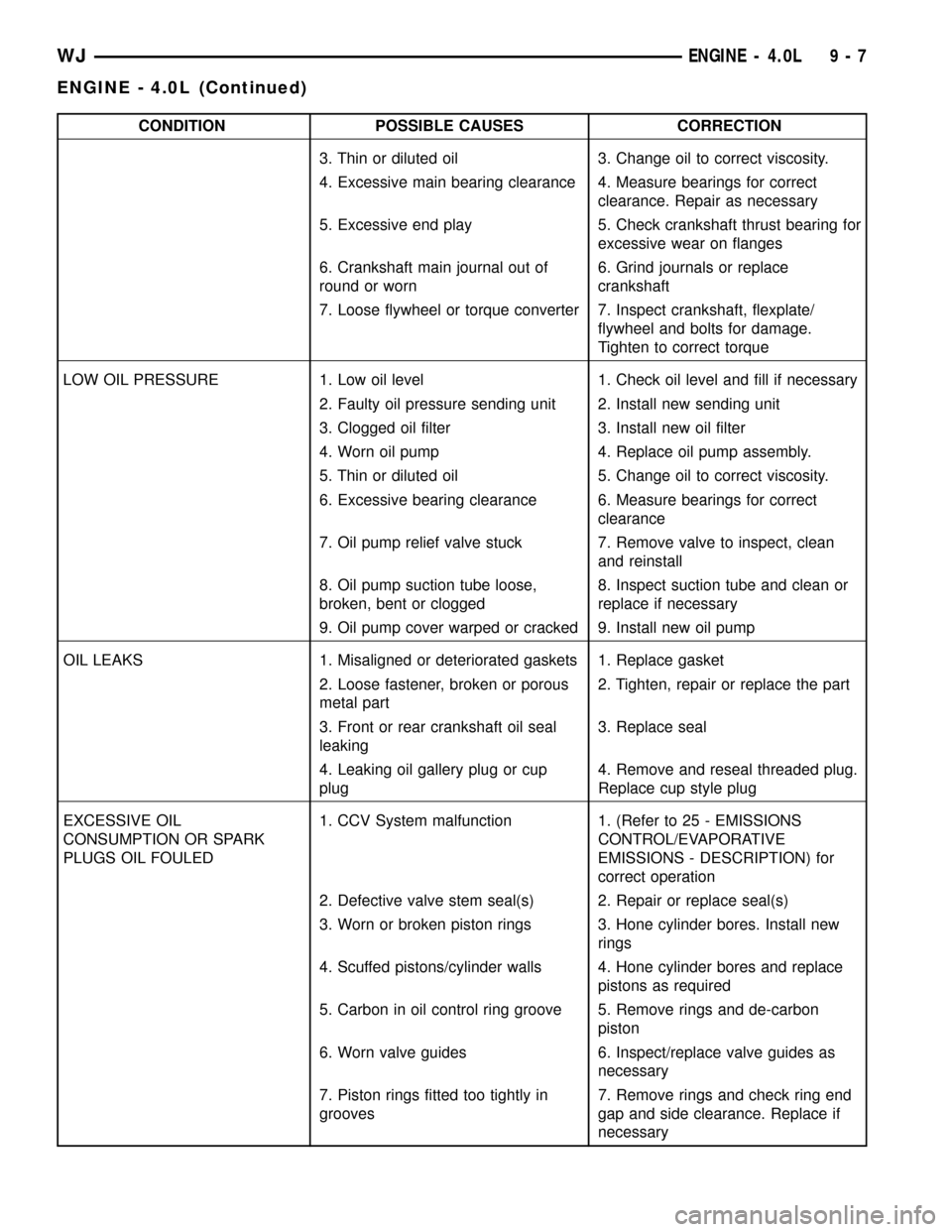
CONDITION POSSIBLE CAUSES CORRECTION
3. Thin or diluted oil 3. Change oil to correct viscosity.
4. Excessive main bearing clearance 4. Measure bearings for correct
clearance. Repair as necessary
5. Excessive end play 5. Check crankshaft thrust bearing for
excessive wear on flanges
6. Crankshaft main journal out of
round or worn6. Grind journals or replace
crankshaft
7. Loose flywheel or torque converter 7. Inspect crankshaft, flexplate/
flywheel and bolts for damage.
Tighten to correct torque
LOW OIL PRESSURE 1. Low oil level 1. Check oil level and fill if necessary
2. Faulty oil pressure sending unit 2. Install new sending unit
3. Clogged oil filter 3. Install new oil filter
4. Worn oil pump 4. Replace oil pump assembly.
5. Thin or diluted oil 5. Change oil to correct viscosity.
6. Excessive bearing clearance 6. Measure bearings for correct
clearance
7. Oil pump relief valve stuck 7. Remove valve to inspect, clean
and reinstall
8. Oil pump suction tube loose,
broken, bent or clogged8. Inspect suction tube and clean or
replace if necessary
9. Oil pump cover warped or cracked 9. Install new oil pump
OIL LEAKS 1. Misaligned or deteriorated gaskets 1. Replace gasket
2. Loose fastener, broken or porous
metal part2. Tighten, repair or replace the part
3. Front or rear crankshaft oil seal
leaking3. Replace seal
4. Leaking oil gallery plug or cup
plug4. Remove and reseal threaded plug.
Replace cup style plug
EXCESSIVE OIL
CONSUMPTION OR SPARK
PLUGS OIL FOULED1. CCV System malfunction 1. (Refer to 25 - EMISSIONS
CONTROL/EVAPORATIVE
EMISSIONS - DESCRIPTION) for
correct operation
2. Defective valve stem seal(s) 2. Repair or replace seal(s)
3. Worn or broken piston rings 3. Hone cylinder bores. Install new
rings
4. Scuffed pistons/cylinder walls 4. Hone cylinder bores and replace
pistons as required
5. Carbon in oil control ring groove 5. Remove rings and de-carbon
piston
6. Worn valve guides 6. Inspect/replace valve guides as
necessary
7. Piston rings fitted too tightly in
grooves7. Remove rings and check ring end
gap and side clearance. Replace if
necessary
WJENGINE - 4.0L 9 - 7
ENGINE - 4.0L (Continued)
Page 1260 of 2199
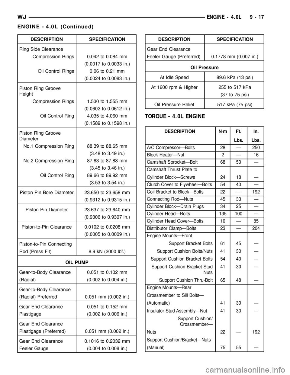
DESCRIPTION SPECIFICATION
Ring Side Clearance
Compression Rings 0.042 to 0.084 mm
(0.0017 to 0.0033 in.)
Oil Control Rings 0.06 to 0.21 mm
(0.0024 to 0.0083 in.)
Piston Ring Groove
Height
Compression Rings 1.530 to 1.555 mm
(0.0602 to 0.0612 in.)
Oil Control Ring 4.035 to 4.060 mm
(0.1589 to 0.1598 in.)
Piston Ring Groove
Diameter
No.1 Compression Ring 88.39 to 88.65 mm
(3.48 to 3.49 in.)
No.2 Compression Ring 87.63 to 87.88 mm
(3.45 to 3.46 in.)
Oil Control Ring 89.66 to 89.92 mm
(3.53 to 3.54 in.)
Piston Pin Bore Diameter 23.650 to 23.658 mm
(0.9312 to 0.9315 in.)
Piston Pin Diameter 23.637 to 23.640 mm
(0.9306 to 0.9307 in.)
Piston-to-Pin Clearance 0.0102 to 0.0208 mm
(0.0005 to 0.0009 in.)
Piston-to-Pin Connecting
Rod (Press Fit) 8.9 kN (2000 lbf.)
OIL PUMP
Gear-to-Body Clearance 0.051 to 0.102 mm
(Radial) (0.002 to 0.004 in.)
Gear-to-Body Clearance
(Radial) Preferred 0.051 mm (0.002 in.)
Gear End Clearance 0.051 to 0.152 mm
Plastigage (0.002 to 0.006 in.)
Gear End Clearance
Plastigage (Preferred) 0.051 mm (0.002 in.)
Gear End Clearance 0.1016 to 0.2032 mm
Feeler Gauge (0.004 to 0.008 in.)DESCRIPTION SPECIFICATION
Gear End Clearance
Feeler Gauge (Preferred) 0.1778 mm (0.007 in.)
Oil Pressure
At Idle Speed 89.6 kPa (13 psi)
At 1600 rpm & Higher 255 to 517 kPa
(37 to 75 psi)
Oil Pressure Relief 517 kPa (75 psi)
TORQUE - 4.0L ENGINE
DESCRIPTION N´m Ft. In.
Lbs. Lbs.
A/C CompressorÐBolts 28 Ð 250
Block HeaterÐNut 2 Ð 16
Camshaft SprocketÐBolt 68 50 Ð
Camshaft Thrust Plate to
Cylinder BlockÐScrews 24 18 Ð
Clutch Cover to FlywheelÐBolts 54 40 Ð
Coil Bracket to BlockÐBolts 22 Ð 192
Connecting RodÐNuts 45 33 Ð
Cylinder BlockÐDrain Plugs 34 25 Ð
Cylinder HeadÐBolts 135 100 Ð
Cylinder Head CoverÐBolts 10 Ð 85
Distributor ClampÐBolts 23 Ð 204
Engine MountsÐFront
Support Bracket Bolts 61 45 Ð
Support Cushion Bolts/Nuts 41 30 Ð
Support Cushion Bracket Bolts 54 40 Ð
Support Cushion Bracket Stud
Nuts41 30 Ð
Support Cushion Thru-Bolt 65 48 Ð
Engine MountsÐRear
Crossmember to Sill BoltsÐ
(Automatic) 41 30 Ð
Insulator Stud AssemblyÐNut 41 30 Ð
Support Cushion/
CrossmemberÐ
Nuts 22 Ð 192
Support Cushion/BracketÐNuts
(Manual) 75 55 Ð
WJENGINE - 4.0L 9 - 17
ENGINE - 4.0L (Continued)
Page 1274 of 2199

REMOVAL
REMOVAL - CAMSHAFT BEARINGS
The camshaft rotates within four steel-shelled,
babbitt-lined bearings that are pressed into the cyl-
inder block and then line reamed. The camshaft
bearing bores and bearing diameters are not the
same size. They are stepped down in 0.254 mm
(0.010 inch) increments from the front bearing (larg-
est) to the rear bearing (smallest). This permits eas-
ier removal and installation of the camshaft. The
camshaft bearings are pressure lubricated. Camshaft
end play is maintained by the thrust plate.
(1) Remove the camshaft (Refer to 9 - ENGINE/
ENGINE BLOCK/CAMSHAFT & BEARINGS (IN
BLOCK) - REMOVAL).
NOTE: It is not advisable to attempt to replace cam-
shaft bearings unless special removal and installa-
tion tools are available, such as recommended tool
8544 Camshaft Bushing Remover Installer.
(2) Using Special tool 8544 Camshaft Bushing
Remover Installer, remove the camshaft bearings.
REMOVAL - CAMSHAFT
WARNING: THE COOLANT IN A RECENTLY OPER-
ATED ENGINE IS HOT AND PRESSURIZED.RELEASE THE PRESSURE BEFORE REMOVING
THE DRAIN COCK, CAP AND DRAIN PLUGS.
(1) Disconnect negative cable from battery.
(2) Drain the cooling system (Refer to 7 - COOL-
ING - STANDARD PROCEDURE).
(3) Remove the radiator (Refer to 7 - COOLING/
ENGINE/RADIATOR - REMOVAL) and condenser
(Refer to 24 - HEATING & AIR CONDITIONING/
PLUMBING/A/C CONDENSER - REMOVAL), if
equipped with A/C.
(4) Remove the engine cylinder head cover (Refer
to 9 - ENGINE/CYLINDER HEAD/CYLINDER
HEAD COVER(S) - REMOVAL).
(5) Remove the rocker arms, bridges and pivots
(Refer to 9 - ENGINE/CYLINDER HEAD/ROCKER
ARM / ADJUSTER ASSY - REMOVAL).
(6) Remove the push rods.
(7) Remove the engine cylinder head and gasket
(Refer to 9 - ENGINE/CYLINDER HEAD - REMOV-
AL).
(8) Remove the hydraulic valve tappets from the
engine cylinder block (Refer to 9 - ENGINE/ENGINE
BLOCK/HYDRAULIC LIFTERS (CAM IN BLOCK) -
REMOVAL).
(9) Remove the vibration damper (Refer to 9 -
ENGINE/ENGINE BLOCK/VIBRATION DAMPER -
REMOVAL).
(10) Remove the timing case cover (Refer to 9 -
ENGINE/VALVE TIMING/TIMING BELT / CHAIN
COVER(S) - REMOVAL).
(11) Rotate the crankshaft until the crankshaft
sprocket timing mark is aligned on centerline with
the camshaft sprocket timing mark (Fig. 32).
(12) Remove the timing chain and sprockets (Refer
to 9 - ENGINE/VALVE TIMING/TIMING BELT/
CHAIN AND SPROCKETS - REMOVAL).
(13) Remove the front bumper and/or grille, as
required.
(14) Remove the two thrust plate retaining screws,
thrust plate and camshaft (Fig. 31).
INSPECTION
INSPECTION - CAMSHAFT BEARINGS
(1) Inspect the bearing journals for uneven wear
pattern or finish.
(2) Inspect the bearings for wear.
INSPECTION - CAMSHAFT
(1) Inspect the cam lobes for wear.
(2) Inspect the camshaft position sensor drive gear
for wear.
(3) If the camshaft appears to have been rubbing
against the thrust washer, examine the oil pressure
Fig. 30 CamshaftÐTypical
1 - CAMSHAFT
2 - LOBES
3 - BEARING JOURNAL
WJENGINE - 4.0L 9 - 31
CAMSHAFT & BEARINGS (Continued)