2003 JEEP GRAND CHEROKEE Lift
[x] Cancel search: LiftPage 12 of 2199
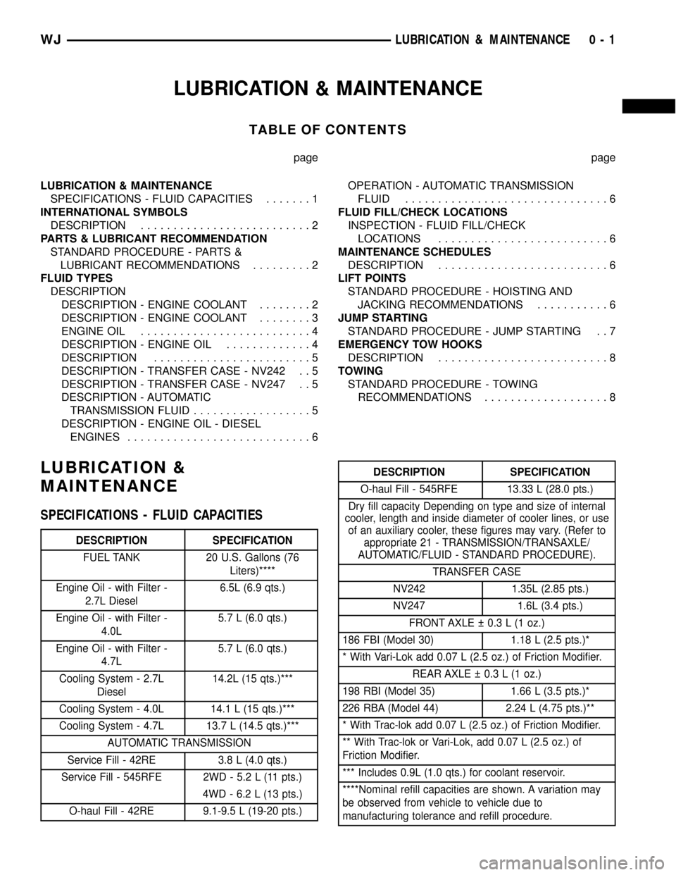
LUBRICATION & MAINTENANCE
TABLE OF CONTENTS
page page
LUBRICATION & MAINTENANCE
SPECIFICATIONS - FLUID CAPACITIES.......1
INTERNATIONAL SYMBOLS
DESCRIPTION..........................2
PARTS & LUBRICANT RECOMMENDATION
STANDARD PROCEDURE - PARTS &
LUBRICANT RECOMMENDATIONS.........2
FLUID TYPES
DESCRIPTION
DESCRIPTION - ENGINE COOLANT........2
DESCRIPTION - ENGINE COOLANT........3
ENGINE OIL..........................4
DESCRIPTION - ENGINE OIL.............4
DESCRIPTION........................5
DESCRIPTION - TRANSFER CASE - NV242 . . 5
DESCRIPTION - TRANSFER CASE - NV247 . . 5
DESCRIPTION - AUTOMATIC
TRANSMISSION FLUID..................5
DESCRIPTION - ENGINE OIL - DIESEL
ENGINES............................6OPERATION - AUTOMATIC TRANSMISSION
FLUID...............................6
FLUID FILL/CHECK LOCATIONS
INSPECTION - FLUID FILL/CHECK
LOCATIONS..........................6
MAINTENANCE SCHEDULES
DESCRIPTION..........................6
LIFT POINTS
STANDARD PROCEDURE - HOISTING AND
JACKING RECOMMENDATIONS...........6
JUMP STARTING
STANDARD PROCEDURE - JUMP STARTING . . 7
EMERGENCY TOW HOOKS
DESCRIPTION..........................8
TOWING
STANDARD PROCEDURE - TOWING
RECOMMENDATIONS...................8
LUBRICATION &
MAINTENANCE
SPECIFICATIONS - FLUID CAPACITIES
DESCRIPTION SPECIFICATION
FUEL TANK 20 U.S. Gallons (76
Liters)****
Engine Oil - with Filter -
2.7L Diesel6.5L (6.9 qts.)
Engine Oil - with Filter -
4.0L5.7 L (6.0 qts.)
Engine Oil - with Filter -
4.7L5.7 L (6.0 qts.)
Cooling System - 2.7L
Diesel14.2L (15 qts.)***
Cooling System - 4.0L 14.1 L (15 qts.)***
Cooling System - 4.7L 13.7 L (14.5 qts.)***
AUTOMATIC TRANSMISSION
Service Fill - 42RE 3.8 L (4.0 qts.)
Service Fill - 545RFE 2WD - 5.2 L (11 pts.)
4WD - 6.2 L (13 pts.)
O-haul Fill - 42RE 9.1-9.5 L (19-20 pts.)
DESCRIPTION SPECIFICATION
O-haul Fill - 545RFE 13.33 L (28.0 pts.)
Dry fill capacity Depending on type and size of internal
cooler, length and inside diameter of cooler lines, or use
of an auxiliary cooler, these figures may vary. (Refer to
appropriate 21 - TRANSMISSION/TRANSAXLE/
AUTOMATIC/FLUID - STANDARD PROCEDURE).
TRANSFER CASE
NV242 1.35L (2.85 pts.)
NV247 1.6L (3.4 pts.)
FRONT AXLE 0.3 L (1 oz.)
186 FBI (Model 30) 1.18 L (2.5 pts.)*
* With Vari-Lok add 0.07 L (2.5 oz.) of Friction Modifier.
REAR AXLE 0.3 L (1 oz.)
198 RBI (Model 35) 1.66 L (3.5 pts.)*
226 RBA (Model 44) 2.24 L (4.75 pts.)**
* With Trac-lok add 0.07 L (2.5 oz.) of Friction Modifier.
** With Trac-lok or Vari-Lok, add 0.07 L (2.5 oz.) of
Friction Modifier.
*** Includes 0.9L (1.0 qts.) for coolant reservoir.
****Nominal refill capacities are shown. A variation may
be observed from vehicle to vehicle due to
manufacturing tolerance and refill procedure.
WJLUBRICATION & MAINTENANCE 0 - 1
Page 17 of 2199

DESCRIPTION - ENGINE OIL - DIESEL
ENGINES
Use only Diesel Engine Oil meeting standardMIL-
2104Cor API ClassificationCD or higherorCCML
D4, D5.
SAE VISCOSITY GRADE
CAUTION: Low viscosity oils must have the proper
API quality or the CCMC G5 designation.
To assure of properly formulated engine oils, it is
recommended that SAE Grade 10W-40 engine oils
that meet Chrysler material standard MS-6395, be
used. European Grade 10W-40 oils are also accept-
able.
Oils of the SAE 5W-40 or 8W-80 grade number are
preferred when minimum temperatures consistently
fall below -12ÉC.
OPERATION - AUTOMATIC TRANSMISSION
FLUID
The automatic transmission fluid is selected based
upon several qualities. The fluid must provide a high
level of protection for the internal components by
providing a lubricating film between adjacent metal
components. The fluid must also be thermally stable
so that it can maintain a consistent viscosity through
a large temperature range. If the viscosity stays con-
stant through the temperature range of operation,
transmission operation and shift feel will remain con-
sistent. Transmission fluid must also be a good con-
ductor of heat. The fluid must absorb heat from the
internal transmission components and transfer that
heat to the transmission case.
FLUID FILL/CHECK
LOCATIONS
INSPECTION - FLUID FILL/CHECK LOCATIONS
The fluid fill/check locations and lubrication points
are located in each applicable group.
MAINTENANCE SCHEDULES
DESCRIPTION
9Maintenance Schedule Information not included in
this section, is located in the appropriate Owner's
Manual.9
LIFT POINTS
STANDARD PROCEDURE - HOISTING AND
JACKING RECOMMENDATIONS
FLOOR JACK
When properly positioned, a floor jack can be used
to lift a WJ vehicle (Fig. 7). Support the vehicle in
the raised position with jack stands at the front and
rear ends of the frame rails.
CAUTION: Do not attempt to lift a vehicle with a
floor jack positioned under:
²An axle tube.
²Aluminum differential.
²A body side sill.
²A steering linkage component.
²A drive shaft.
²The engine or transmission oil pan.
²The fuel tank.
²A front suspension arm.
HOIST
A vehicle can be lifted with:
²A single-post, frame-contact hoist.
²A twin-post, chassis hoist.
²A ramp-type, drive-on hoist.
NOTE: When a frame-contact type hoist is used,
verify that the lifting pads are positioned properly
(Fig. 7).
WARNING: THE HOISTING AND JACK LIFTING
POINTS PROVIDED ARE FOR A COMPLETE VEHI-
CLE. WHEN A CHASSIS OR DRIVETRAIN COMPO-
NENT IS REMOVED FROM A VEHICLE, THE
CENTER OF GRAVITY IS ALTERED MAKING SOME
HOISTING CONDITIONS UNSTABLE. PROPERLY
SUPPORT OR SECURE VEHICLE TO HOISTING
DEVICE WHEN THESE CONDITIONS EXIST.
0 - 6 LUBRICATION & MAINTENANCEWJ
FLUID TYPES (Continued)
Page 18 of 2199

JUMP STARTING
STANDARD PROCEDURE - JUMP STARTING
WARNING: REVIEW ALL SAFETY PRECAUTIONS
AND WARNINGS IN GROUP 8A, BATTERY/START-
ING/CHARGING SYSTEMS DIAGNOSTICS. DO NOT
JUMP START A FROZEN BATTERY, PERSONAL
INJURY CAN RESULT. DO NOT JUMP START WHEN
MAINTENANCE FREE BATTERY INDICATOR DOT IS
YELLOW OR BRIGHT COLOR. DO NOT JUMP
START A VEHICLE WHEN THE BATTERY FLUID IS
BELOW THE TOP OF LEAD PLATES. DO NOT
ALLOW JUMPER CABLE CLAMPS TO TOUCH
EACH OTHER WHEN CONNECTED TO A BOOSTER
SOURCE. DO NOT USE OPEN FLAME NEAR BAT-
TERY. REMOVE METALLIC JEWELRY WORN ON
HANDS OR WRISTS TO AVOID INJURY BY ACCI-
DENTAL ARCING OF BATTERY CURRENT. WHEN
USING A HIGH OUTPUT BOOSTING DEVICE, DO
NOT ALLOW BATTERY VOLTAGE TO EXCEED 16
VOLTS. REFER TO INSTRUCTIONS PROVIDED
WITH DEVICE BEING USED.
CAUTION: When using another vehicle as a
booster, do not allow vehicles to touch. Electrical
systems can be damaged on either vehicle.
TO JUMP START A DISABLED VEHICLE:
(1) Raise hood on disabled vehicle and visually
inspect engine compartment for:
²Battery cable clamp condition, clean if necessary.
²Frozen battery.
²Yellow or bright color test indicator, if equipped.
²Low battery fluid level.
²Generator drive belt condition and tension.
²Fuel fumes or leakage, correct if necessary.
CAUTION: If the cause of starting problem on dis-
abled vehicle is severe, damage to booster vehicle
charging system can result.
(2) When using another vehicle as a booster
source, park the booster vehicle within cable reach.
Turn off all accessories, set the parking brake, place
the automatic transmission in PARK or the manual
transmission in NEUTRAL and turn the ignition
OFF.
(3) On disabled vehicle, place gear selector in park
or neutral and set park brake. Turn off all accesso-
ries.
(4) Connect jumper cables to booster battery. RED
clamp to positive terminal (+). BLACK clamp to neg-
ative terminal (-). DO NOT allow clamps at opposite
end of cables to touch, electrical arc will result.
Review all warnings in this procedure.
(5) On disabled vehicle, connect RED jumper cable
clamp to positive (+) terminal. Connect BLACK
jumper cable clamp to engine ground as close to the
ground cable attaching point as possible (Fig. 8).
(6) Start the engine in the vehicle which has the
booster battery, let the engine idle a few minutes,
then start the engine in the vehicle with the dis-
charged battery.
CAUTION: Do not crank starter motor on disabled
vehicle for more than 15 seconds, starter will over-
heat and could fail.
(7) Allow battery in disabled vehicle to charge to
at least 12.4 volts (75% charge) before attempting to
start engine. If engine does not start within 15 sec-
onds, stop cranking engine and allow starter to cool
(15 min.), before cranking again.
Fig. 7 Correct Vehicle Lifting Locations
WJLUBRICATION & MAINTENANCE 0 - 7
LIFT POINTS (Continued)
Page 19 of 2199

DISCONNECT CABLE CLAMPS AS FOLLOWS:
²Disconnect BLACK cable clamp from engine
ground on disabled vehicle.
²When using a Booster vehicle, disconnect
BLACK cable clamp from battery negative terminal.
Disconnect RED cable clamp from battery positive
terminal.
²Disconnect RED cable clamp from battery posi-
tive terminal on disabled vehicle.
EMERGENCY TOW HOOKS
DESCRIPTION
WARNING: REMAIN AT A SAFE DISTANCE FROM A
VEHICLE THAT IS BEING TOWED VIA ITS TOW
HOOKS. THE TOW STRAPS/CHAINS COULD BREAK
AND CAUSE SERIOUS INJURY.
Some Jeep vehicles are equipped with front emer-
gency tow hooks (Fig. 9). The tow hooks should be
used forEMERGENCYpurposes only.
CAUTION: DO NOT use emergency tow hooks for
tow truck hook-up or highway towing.
TOWING
STANDARD PROCEDURE - TOWING
RECOMMENDATIONS
A vehicle equipped with SAE approved wheel lift-
type towing equipment can be used to tow WJ vehi-
cles. When towing a 4WD vehicle using a wheel-lift
towing device, use tow dollies under the opposite end
of the vehicle. A vehicle with flatbed device can also
be used to transport a disabled vehicle (Fig. 10).
SAFETY PRECAUTIONS
CAUTION: The following safety precautions must be
observed when towing a vehicle:
²Secure loose and protruding parts.
²Always use a safety chain system that is inde-
pendent of the lifting and towing equipment.
Fig. 8 Jumper Cable Clamp Connections
1 - ENGINE GROUND
2 - NEGATIVE JUMPER CABLE
3 - BATTERY NEGATIVE CABLE
4 - POSITIVE JUMPER CABLE
5 - BATTERY POSITIVE CABLE
6 - BATTERY
7 - TEST INDICATOR
Fig. 9 Emergency Tow Hooks
1 - TOW HOOK
Fig. 10 Tow Vehicles With Approved Equipment
0 - 8 LUBRICATION & MAINTENANCEWJ
JUMP STARTING (Continued)
Page 20 of 2199

²Do not allow towing equipment to contact the
disabled vehicle's fuel tank.
²Do not allow anyone under the disabled vehicle
while it is lifted by the towing device.
²Do not allow passengers to ride in a vehicle
being towed.
²Always observe state and local laws regarding
towing regulations.
²Do not tow a vehicle in a manner that could
jeopardize the safety of the operator, pedestrians or
other motorists.
²Do not attach tow chains, T-hooks, or J-hooks to
a bumper, steering linkage, drive shafts or a non-re-
inforced frame hole.
²Do not tow a heavily loaded vehicle. Use a flat-
bed device to transport a loaded vehicle.
TWO-WHEEL-DRIVE VEHICLE TOWING
DaimlerChrysler Corporation recommends that a
vehicle be towed with the rear end lifted, whenever
possible.
WARNING: WHEN TOWING A DISABLED VEHICLE
AND THE DRIVE WHEELS ARE SECURED IN A
WHEEL LIFT OR TOW DOLLIES, ENSURE THE
TRANSMISSION IS IN THE PARK POSITION (AUTO-
MATIC TRANSMISSION) OR A FORWARD DRIVE
GEAR (MANUAL TRANSMISSION).
WARNING: ENSURE VEHICLE IS ON A LEVEL SUR-
FACE OR THE WHEELS ARE BLOCKED TO PRE-
VENT VEHICLE FROM ROLLING.
TWO WHEEL DRIVE TOWING-REAR END LIFTED
CAUTION: Do not use steering column lock to
secure steering wheel during towing operation.
2WD vehicles can be towed with the front wheels
on the surface for extended distances at speeds not
exceeding 48 km/h (30 mph).
(1) Attach wheel lift device to rear wheels.
(2) Place the transmission in neutral.
(3) Raise vehicle to towing position.
(4) Attach safety chains. Route chains so not to
interfere with tail pipe when vehicle is lifted.
(5) Turn the ignition switch to the OFF position to
unlock the steering wheel.
CAUTION: Do not use steering column lock to
secure steering wheel during towing operation.
(6) Secure steering wheel in straight ahead posi-
tion with a clamp device designed for towing.
(7) Place transmission in park.
TWO WHEEL DRIVE TOWING-FRONT END LIFTED
CAUTION: Many vehicles are equipped with air
dams, spoilers, and/or ground effect panels. To
avoid component damage, a wheel-lift towing vehi-
cle or a flat-bed hauling vehicle is recommended.
(1) Attach wheel lift device to rear wheels.
(2) Place the transmission in neutral.
(3) Raise the rear of the vehicle off the ground and
install tow dollies under rear wheels.
(4) Attach wheel lift device to front wheels and
raise vehicle to towing position.
(5) Attach the safety chains.
CAUTION: Do not use steering column lock to
secure steering wheel during towing operation.
(6) Turn the ignition switch to the OFF position to
unlock the steering wheel.
(7) Secure steering wheel in straight ahead posi-
tion with a clamp device designed for towing.
(8) Place transmission in park.
FOUR-WHEEL-DRIVE VEHICLE TOWING
DaimlerChrysler Corporation recommends that a
4WD vehicle be transported on a flat-bed device. A
Wheel-lift device can be used providedthe trailing
wheels are off the ground and positioned in
tow dollies.
WARNING: WHEN TOWING A DISABLED VEHICLE
AND THE DRIVE WHEELS ARE SECURED IN A
WHEEL LIFT OR TOW DOLLIES, ENSURE THE
TRANSMISSION IS IN THE PARK POSITION.
CAUTION: Many vehicles are equipped with air
dams, spoilers, and/or ground effect panels. To
avoid component damage, a wheel-lift towing vehi-
cle or a flat-bed hauling vehicle is recommended.
FOUR WHEEL DRIVE TOWINGÐREAR END LIFTED
WARNING: ENSURE VEHICLE IS ON A LEVEL SUR-
FACE OR THE WHEELS ARE BLOCKED TO PRE-
VENT VEHICLE FROM ROLLING.
(1) Attach wheel lift device to front wheels.
(2) Place the transmission in neutral.
(3) Raise the front of the vehicle off the ground
and install tow dollies under front wheels.
(4) Attach wheel lift device to rear wheels and
raise vehicle to towing position.
(5) Attach safety chains. Route chains so not to
interfere with tail pipe when vehicle is lifted.
WJLUBRICATION & MAINTENANCE 0 - 9
TOWING (Continued)
Page 21 of 2199

(6) Turn the ignition switch to the OFF position to
unlock the steering wheel.
CAUTION: Do not use steering column lock to
secure steering wheel during towing operation.
(7) Secure steering wheel in straight ahead posi-
tion with a clamp device designed for towing.
(8) Place transmission in park.
FOUR WHEEL DRIVE TOWINGÐFRONT END
LIFTED
WARNING: ENSURE VEHICLE IS ON A LEVEL SUR-
FACE OR THE WHEELS ARE BLOCKED TO PRE-
VENT VEHICLE FROM ROLLING.
(1) Attach wheel lift device to rear wheels.(2) Place the transmission in neutral.
(3) Raise the rear of the vehicle off the ground and
install tow dollies under rear wheels.
(4) Attach wheel lift device to front wheels and
raise vehicle to towing position.
(5) Attach the safety chains.
CAUTION: Do not use steering column lock to
secure steering wheel during towing operation.
(6) Turn the ignition switch to the OFF position to
unlock the steering wheel.
(7) Secure steering wheel in straight ahead posi-
tion with a clamp device designed for towing.
(8) Place transmission in park.
0 - 10 LUBRICATION & MAINTENANCEWJ
TOWING (Continued)
Page 59 of 2199

FRONT TUBE AXLE
TABLE OF CONTENTS
page page
FRONT TUBE AXLE
REMOVAL.............................14INSTALLATION.........................14
FRONT TUBE AXLE
REMOVAL
(1) Raise and support the vehicle.
(2) Position a lifting device under the axle and
secure axle to lift.
(3) Remove the wheels and tires.
(4) Remove the brake rotors (Refer to 5 - BRAKES/
HYDRAULIC/MECHANICAL/ROTORS - REMOVAL)
and calipers.
(5) Disconnect wheel sensor wiring harness from
the vehicle wiring harness.
(6) Remove stabilizer bar links at the axle.
(7) Remove shock absorbers from axle brackets.
(8) Removet track bar.
(9) Remove tie rod and drag link from the steering
knuckle.
(10) Remove steering damper from the axle
bracket.
(11) Remove upper and lower suspension arms
from the axle brackets.
(12) Lower the lift enough to remove the axle. The
coil springs will drop with the axle.
(13) Remove the coil springs from the axle.
INSTALLATION
CAUTION: The weight of the vehicle must be sup-
ported by the springs before suspension arms and
track bar fasteners are tightened. If not at their nor-mal ride position, ride height and handling could be
affected.
(1) Install springs and retainer clips and tighten
retainer bolts to 21 N´m (16 ft. lbs.).
(2) Lift and position axle under the vehicle and
align it with the spring pads.
(3) Position upper and lower suspension arms in
the axle brackets and loosely install bolts and nuts.
(4) Install track bar to the axle bracket and loosely
install bolt.
(5) Install shock absorbers and tighten bolts to 23
N´m (17 ft. lbs.).
(6) Install stabilizer bar links to the axle brackets
and tighten nuts to 95 N´m (70 ft. lbs.).
(7) Install drag link and tie rod to the steering
knuckles.
(8) Install steering damper to the axle bracket and
tighten nut to 75 N´m (55 ft. lbs.).
(9) Install the brake rotors and calipers.
(10) Connect wheel speed sensor wiring harness, if
equipped.
(11) Install the wheel and tire assemblies.
(12) Remove lift from the axle and lower the vehi-
cle.
(13) Tighten upper suspension arm nuts to 75 N´m
(55 ft. lbs.). Tighten lower suspension arm nuts to
115 N´m (85 ft. lbs.).
(14) Tighten track bar bolt at the axle bracket to
100 N´m (74 ft. lbs.).
(15) Check the front wheel alignment.
3 - 14 FRONT TUBE AXLEWJ
Page 65 of 2199

Condition Possible Causes Correction
Axle Noise 1. Insufficient lubricant. 1. Fill differential with the correct
fluid type and quantity.
2. Improper ring gear and pinion
adjustment.2. Check ring gear and pinion
contact pattern.
3. Unmatched ring gear and pinion. 3. Replace gears with a matched
ring gear and pinion.
4. Worn teeth on ring gear and/or
pinion.4. Replace ring gear and pinion.
5. Loose pinion bearings. 5. Adjust pinion bearing pre-load.
6. Loose differential bearings. 6. Adjust differential bearing
pre-load.
7. Mis-aligned or sprung ring gear. 7. Measure ring gear run-out.
Replace components as necessary.
8. Loose differential bearing cap
bolts.8. Inspect differential components
and replace as necessary. Ensure
that the bearing caps are torqued
tot he proper specification.
9. Housing not machined properly. 9. Replace housing.
VARI-LOKT
(1) Park the vehicle on a level surface or raise
vehicle on hoist so that the vehicle is level.
(2) Remove the axle fill plug.
(3) Verify that the axle fluid level is correct. The
fluid level is correct if the fluid is level with the bot-
tom of the fill hole.
(4) Shift the transfer case into the 4WD full-time
position.
(5) Drive the vehicle in a tight circle for 2 minutes
at 5mph to fully prime the pump.
(6) Block the tires opposite the axle to be tested to
prevent the vehicle from moving.
(7) Shift the transfer case into the 4WD Low posi-
tion and the transmission into the Park position.
(8) Raise both the wheels of the axle to be tested
off of the ground.
(9) Rotate the left wheel by hand at a minimum of
one revolution per second while an assistant rotates
the right wheel in the opposite direction.
(10) The left wheel should spin freely at first and
then increase in resistance within 5 revolutions until
the wheels cannot be continuously rotated in opposite
directions.
(11) The Vari-loktdifferential has engaged prop-
erly if the wheels cannot be rotated in opposite direc-
tions for a moment. After the wheels stop rotating for
a moment, the fluid pressure will drop in the differ-
ential and the wheels begin to rotate once again.
(12) If the system does not operate properly,
replace the Vari-loktdifferential.
REMOVAL
(1) Raise and support the vehicle.
(2) Position a suitable lifting device under the
axle.
(3) Secure axle to lift.
(4) Remove the wheels and tires.
(5) Remove the brake calipers and rotors (Refer to
5 - BRAKES/HYDRAULIC/MECHANICAL/ROTORS
- REMOVAL) from the axle.
(6) Disconnect the wheel sensor wiring harness
from the vehicle wiring harness.
(7) Disconnect the vent hose from the axle shaft
tube.
(8) Mark propeller shaft and yoke/pinion flange for
installation alignment reference.
(9) Remove propeller shaft.
(10) Disconnect stabilizer bar links at the axle.
(11) Disconnect shock absorbers from axle brack-
ets.
(12) Disconnect track bar.
(13) Disconnect the tie rod and drag link from the
steering knuckle.
(14) Disconnect the steering damper from the axle
bracket.
(15) Disconnect the upper and lower suspension
arms from the axle brackets.
(16) Lower the lifting device enough to remove the
axle. The coil springs will drop with the axle.
(17) Remove the coil springs from the axle.
3 - 20 FRONT AXLE - 186FBIWJ
FRONT AXLE - 186FBI (Continued)