2003 JEEP GRAND CHEROKEE Evap system
[x] Cancel search: Evap systemPage 9 of 2199
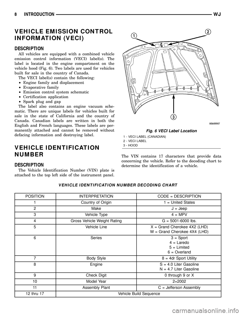
VEHICLE EMISSION CONTROL
INFORMATION (VECI)
DESCRIPTION
All vehicles are equipped with a combined vehicle
emission control information (VECI) label(s). The
label is located in the engine compartment on the
vehicle hood (Fig. 6). Two labels are used for vehicles
built for sale in the country of Canada.
The VECI label(s) contain the following:
²Engine family and displacement
²Evaporative family
²Emission control system schematic
²Certification application
²Spark plug and gap
The label also contains an engine vacuum sche-
matic. There are unique labels for vehicles built for
sale in the state of California and the country of
Canada. Canadian labels are written in both the
English and French languages. These labels are per-
manently attached and cannot be removed without
defacing information and destroying label.
VEHICLE IDENTIFICATION
NUMBER
DESCRIPTION
The Vehicle Identification Number (VIN) plate is
attached to the top left side of the instrument panel.The VIN contains 17 characters that provide data
concerning the vehicle. Refer to the decoding chart to
determine the identification of a vehicle.
VEHICLE IDENTIFICATION NUMBER DECODING CHART
POSITION INTERPRETATION CODE = DESCRIPTION
1 Country of Origin 1 = United States
2 Make J = Jeep
3 Vehicle Type 4 = MPV
4 Gross Vehicle Weight Rating G = 5001-6000 lbs.
5 Vehicle Line X = Grand Cherokee 4X2 (LHD)
W = Grand Cherokee 4X4 (LHD)
6 Series 3 = Sport
4 = Laredo
5 = Limited
6 = Overland
7 Body Style 8 = 4dr Sport Utility
8 Engine S = 4.0 Liter Gasoline
N = 4.7 Liter Gasoline
9 Check Digit 0 through 9 or X
10 Model Year 2=2002
11 Assembly Plant C = Jefferson Assembly
12 thru 17 Vehicle Build Sequence
Fig. 6 VECI Label Location
1 - VECI LABEL (CANADIAN)
2 - VECI LABEL
3 - HOOD
8 INTRODUCTIONWJ
Page 232 of 2199
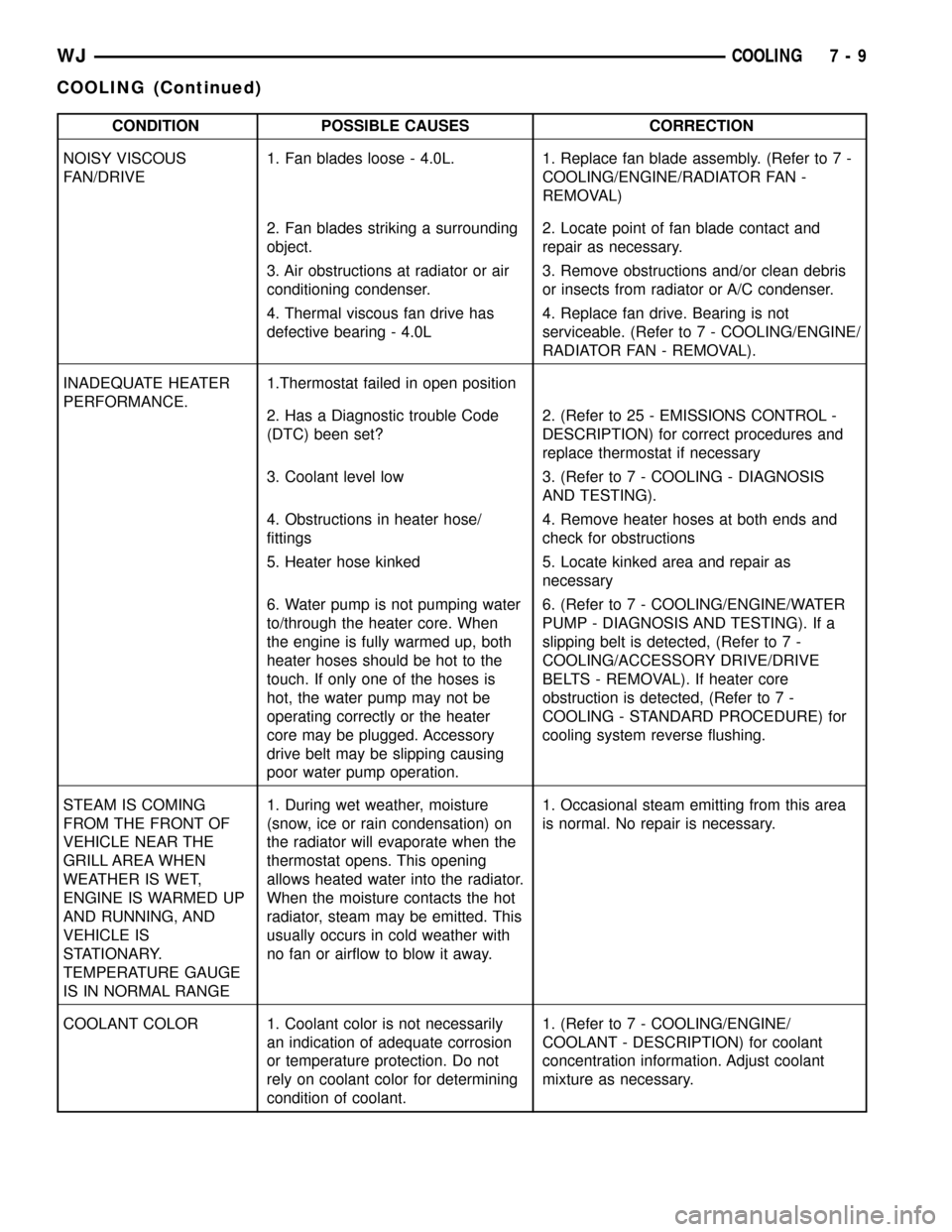
CONDITION POSSIBLE CAUSES CORRECTION
NOISY VISCOUS
FAN/DRIVE1. Fan blades loose - 4.0L. 1. Replace fan blade assembly. (Refer to 7 -
COOLING/ENGINE/RADIATOR FAN -
REMOVAL)
2. Fan blades striking a surrounding
object.2. Locate point of fan blade contact and
repair as necessary.
3. Air obstructions at radiator or air
conditioning condenser.3. Remove obstructions and/or clean debris
or insects from radiator or A/C condenser.
4. Thermal viscous fan drive has
defective bearing - 4.0L4. Replace fan drive. Bearing is not
serviceable. (Refer to 7 - COOLING/ENGINE/
RADIATOR FAN - REMOVAL).
INADEQUATE HEATER
PERFORMANCE.1.Thermostat failed in open position
2. Has a Diagnostic trouble Code
(DTC) been set?2. (Refer to 25 - EMISSIONS CONTROL -
DESCRIPTION) for correct procedures and
replace thermostat if necessary
3. Coolant level low 3. (Refer to 7 - COOLING - DIAGNOSIS
AND TESTING).
4. Obstructions in heater hose/
fittings4. Remove heater hoses at both ends and
check for obstructions
5. Heater hose kinked 5. Locate kinked area and repair as
necessary
6. Water pump is not pumping water
to/through the heater core. When
the engine is fully warmed up, both
heater hoses should be hot to the
touch. If only one of the hoses is
hot, the water pump may not be
operating correctly or the heater
core may be plugged. Accessory
drive belt may be slipping causing
poor water pump operation.6. (Refer to 7 - COOLING/ENGINE/WATER
PUMP - DIAGNOSIS AND TESTING). If a
slipping belt is detected, (Refer to 7 -
COOLING/ACCESSORY DRIVE/DRIVE
BELTS - REMOVAL). If heater core
obstruction is detected, (Refer to 7 -
COOLING - STANDARD PROCEDURE) for
cooling system reverse flushing.
STEAM IS COMING
FROM THE FRONT OF
VEHICLE NEAR THE
GRILL AREA WHEN
WEATHER IS WET,
ENGINE IS WARMED UP
AND RUNNING, AND
VEHICLE IS
STATIONARY.
TEMPERATURE GAUGE
IS IN NORMAL RANGE1. During wet weather, moisture
(snow, ice or rain condensation) on
the radiator will evaporate when the
thermostat opens. This opening
allows heated water into the radiator.
When the moisture contacts the hot
radiator, steam may be emitted. This
usually occurs in cold weather with
no fan or airflow to blow it away.1. Occasional steam emitting from this area
is normal. No repair is necessary.
COOLANT COLOR 1. Coolant color is not necessarily
an indication of adequate corrosion
or temperature protection. Do not
rely on coolant color for determining
condition of coolant.1. (Refer to 7 - COOLING/ENGINE/
COOLANT - DESCRIPTION) for coolant
concentration information. Adjust coolant
mixture as necessary.
WJCOOLING 7 - 9
COOLING (Continued)
Page 250 of 2199

(1) Position sensor into the coolant recovery pres-
sure container (Fig. 1).
(2) Connect the coolant level sensor electrical con-
nector (Fig. 2).
(3) Close hood.
COOLANT RECOVERY PRESS
CONTAINER
DESCRIPTION
This system works along with the radiator pres-
sure cap. This is done by using thermal expansion
and contraction of the coolant to keep the coolant
free of trapped air. It provides:
²A volume for coolant expansion and contraction.
²A convenient and safe method for checking/ad-
justing coolant level at atmospheric pressure. This is
done without removing the radiator pressure cap.
²Some reserve coolant to the radiator to cover
minor leaks and evaporation or boiling losses.
As the engine cools, a vacuum is formed in the
cooling system of both the radiator and engine. Cool-
ant will then be drawn from the coolant tank and
returned to a proper level in the radiator.
The coolant reservoir/overflow system has a radia-
tor mounted pressurized cap, an overflow tube and a
plastic coolant reservoir/overflow tank (Fig. 3)
mounted to the right inner fender.
RADIATOR FAN - 4.7L
DESCRIPTION
The hydraulic fan (Fig. 4) used on vehicles
equipped the 4.7L engine, replaces both the electric
fan and the engine driven mechanical fan. The
hydraulic cooling fan is integral to the fan shroud
and is located between the radiator and the engine.
The power steering pump supplies the hydraulic
fluid and pressure to rotate the cooling fan blade,
while the electrical part of the fan is controlled by
the JTEC.
The hydraulic fan drive (motor) consists of the
three major following components:
²Steering flow control valve
Fig. 1 COOLANT LEVEL SENSOR ELECTRICAL
CONNECTOR
Fig. 2 COOLANT LEVEL SENSOR REMOVAL/
INSTALLATION
Fig. 3 Coolant Reservoir / Overflow Tank
1 - COOLANT OVERFLOW HOSE
2 - COOLANT RESERVOIR/OVERFLOW TANK
3 - COOLANT LEVEL SENSOR
4 - BOLT
WJENGINE 7 - 27
COOLANT LEVEL SENSOR (Continued)
Page 324 of 2199

DESCRIPTION - POWER GROUNDS
The Powertrain Control Module (PCM) has 2 main
grounds. Both of these grounds are referred to as
power grounds. All of the high-current, noisy, electri-
cal devices are connected to these grounds as well as
all of the sensor returns. The sensor return comes
into the sensor return circuit, passes through noise
suppression, and is then connected to the power
ground.
The power ground is used to control ground cir-
cuits for the following PCM loads:
²Generator field winding
²Fuel injectors
²Ignition coil(s)
²Certain relays/solenoids
²Certain sensors
DESCRIPTION - SENSOR RETURN
The Sensor Return circuits are internal to the Pow-
ertrain Control Module (PCM).
Sensor Return provides a low±noise ground refer-
ence for all engine control system sensors. Refer to
Power Grounds for more information.
OPERATION
OPERATION - PCM
(1) Also refer to Modes of Operation.
The PCM operates the fuel system. The PCM is a
pre-programmed, triple microprocessor digital com-
puter. It regulates ignition timing, air-fuel ratio,
emission control devices, charging system, certain
transmission features, speed control, air conditioning
compressor clutch engagement and idle speed. The
PCM can adapt its programming to meet changing
operating conditions.
The PCM receives input signals from various
switches and sensors. Based on these inputs, the
PCM regulates various engine and vehicle operations
through different system components. These compo-
nents are referred to as Powertrain Control Module
(PCM) Outputs. The sensors and switches that pro-
vide inputs to the PCM are considered Powertrain
Control Module (PCM) Inputs.
The PCM adjusts ignition timing based upon
inputs it receives from sensors that react to: engine
rpm, manifold absolute pressure, engine coolant tem-
perature, throttle position, transmission gear selec-
tion (automatic transmission), vehicle speed and the
brake switch.
The PCM adjusts idle speed based on inputs it
receives from sensors that react to: throttle position,
vehicle speed, transmission gear selection, engine
coolant temperature and from inputs it receives from
the air conditioning clutch switch and brake switch.Based on inputs that it receives, the PCM adjusts
ignition coil dwell. The PCM also adjusts the gener-
ator charge rate through control of the generator
field and provides speed control operation.
NOTE: PCM Inputs:
²A/C request
²Auto shutdown (ASD) sense
²Battery temperature
²Battery voltage
²Brake switch
²J1850 bus circuits
²Camshaft position sensor signal
²Crankshaft position sensor
²Data link connections for DRB scan tool
²Engine coolant temperature sensor
²Five volts (primary)
²Five volts (secondary)
²Fuel level
²Generator (battery voltage) output
²Ignition circuit sense (ignition switch in on/off/
crank/run position)
²Intake manifold air temperature sensor
²Leak detection pump (switch) sense (if equipped)
²Manifold absolute pressure (MAP) sensor
²Oil pressure
²Overdrive/override switch
²Oxygen sensors
²Park/neutral switch (auto. trans. only)
²Power ground
²Sensor return
²Signal ground
²Speed control multiplexed single wire input
²Throttle position sensor
²Transmission governor pressure sensor
²Transmission temperature sensor
²Vehicle speed (from ABS module)
NOTE: PCM Outputs:
²A/C clutch relay
²Auto shutdown (ASD) relay
²J1850 (+/-) circuits for: speedometer, voltmeter,
fuel gauge, oil pressure gauge/lamp, engine temp.
gauge and speed control warn. lamp
²Data link connection for DRBIIItscan tool
²EGR valve control solenoid (if equipped)
²EVAP canister purge solenoid
²Fuel injectors
²Fuel pump relay
²Generator field driver (-)
²Generator field driver (+)
²Generator lamp (if equipped)
²Idle air control (IAC) motor
²Ignition coil
²Leak detection pump
WJELECTRONIC CONTROL MODULES 8E - 15
POWERTRAIN CONTROL MODULE (Continued)
Page 782 of 2199
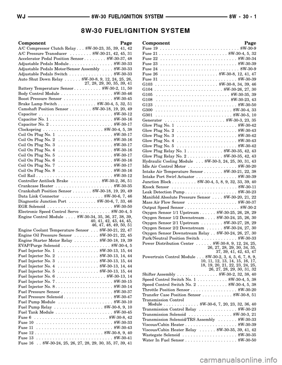
8W-30 FUEL/IGNITION SYSTEM
Component Page
A/C Compressor Clutch Relay . . . 8W-30-23, 35, 39, 41, 42
A/C Pressure Transducer........ 8W-30-21, 42, 45, 31
Accelerator Pedal Position Sensor........ 8W-30-37, 48
Adjustable Pedals Module................ 8W-30-33
Adjustable Pedals Motor/Sensor Assembly.... 8W-30-33
Adjustable Pedals Switch................ 8W-30-33
Auto Shut Down Relay...... 8W-30-8, 9, 12, 24, 25, 26,
27, 28, 29, 30, 35, 39, 41
Battery Temperature Sensor.......... 8W-30-2, 11, 50
Body Control Module................... 8W-30-46
Boost Pressure Sensor.................. 8W-30-45
Brake Lamp Switch.............. 8W-30-4, 5, 32, 51
Camshaft Position Sensor........ 8W-30-18, 19, 20, 49
Capacitor........................... 8W-30-12
Capacitor No. 1....................... 8W-30-16
Capacitor No. 2....................... 8W-30-17
Clockspring...................... 8W-30-4, 5, 38
Coil On Plug No. 1.................... 8W-30-17
Coil On Plug No. 2.................... 8W-30-16
Coil On Plug No. 3.................... 8W-30-17
Coil On Plug No. 4.................... 8W-30-16
Coil On Plug No. 5.................... 8W-30-17
Coil On Plug No. 6.................... 8W-30-16
Coil On Plug No. 7.................... 8W-30-17
Coil On Plug No. 8.................... 8W-30-16
Coil Rail............................ 8W-30-12
Controller Antilock Brake........... 8W-30-2, 36, 51
Crankcase Heater..................... 8W-30-35
Crankshaft Position Sensor....... 8W-30-18, 19, 20, 49
Data Link Connector............... 8W-30-6, 7, 46
Diagnostic Junction Port.......... 8W-30-6, 7, 33, 46
EGR Solenoid........................ 8W-30-50
Electronic Speed Control Servo........... 8W-30-4, 5
Engine Control Module.... 8W-30-34, 35, 36, 37, 38, 39,
40, 41, 42, 43, 44, 45,
46, 47, 48, 49, 50, 51
Engine Coolant Temperature Sensor . . . 8W-30-21, 22, 47
Engine Oil Pressure Sensor......... 8W-30-21, 22, 45
Engine Starter Motor Relay......... 8W-30-18, 19, 39
EVAP/Purge Solenoid.................. 8W-30-4, 5
Fuel Injector No. 1............... 8W-30-13, 15, 44
Fuel Injector No. 2............... 8W-30-13, 14, 44
Fuel Injector No. 3............... 8W-30-13, 15, 44
Fuel Injector No. 4............... 8W-30-13, 14, 44
Fuel Injector No. 5............... 8W-30-13, 15, 44
Fuel Injector No. 6.................. 8W-30-13, 14
Fuel Injector No. 7..................... 8W-30-15
Fuel Injector No. 8..................... 8W-30-14
Fuel Pressure Sensor................... 8W-30-37
Fuel Pressure Solenoid.................. 8W-30-47
Fuel Pump Module.................... 8W-30-10
Fuel Pump Relay.................. 8W-30-8, 9, 10
Fuel Tank Module..................... 8W-30-45
Fuse 6........................... 8W-30-8, 42
Fuse 10............................ 8W-30-33
Fuse 11............................ 8W-30-43
Fuse 12......................... 8W-30-8, 9, 40
Fuse 13............................ 8W-30-41
Fuse 16 . . 8W-30-24, 25, 26, 27, 28, 29, 30, 35, 37, 39, 41
Component Page
Fuse 19............................. 8W-30-9
Fuse 21......................... 8W-30-4, 5, 32
Fuse 22............................ 8W-30-34
Fuse 23............................ 8W-30-39
Fuse 24............................. 8W-30-9
Fuse 26..................... 8W-30-8, 12, 41, 47
Fuse 31............................ 8W-30-39
G103....................... 8W-30-8, 34, 39, 46
G104......................... 8W-30-26, 27, 30
G105........................... 8W-30-35, 39
G108........................... 8W-30-23, 43
G123.............................. 8W-30-50
G300............................ 8W-30-4, 33
G301............................ 8W-30-5, 10
Generator...................... 8W-30-3, 23, 35
Glow Plug No. 1...................... 8W-30-42
Glow Plug No. 2...................... 8W-30-43
Glow Plug No. 3...................... 8W-30-42
Glow Plug No. 4...................... 8W-30-43
Glow Plug No. 5...................... 8W-30-42
Glow Plug Relay No. 1............. 8W-30-35, 42, 43
Glow Plug Relay No. 2............. 8W-30-35, 42, 43
Hydraulic Cooling Module . . . 8W-30-3, 24, 25, 30, 31, 43
Idle Air Control Motor.................. 8W-30-20
Intake Air Temperature Sensor....... 8W-30-21, 22, 38
Intake Port Swirl Actuator............... 8W-30-39
Junction Block......... 8W-30-4, 5, 8, 9, 32, 33, 39, 40
Knock Sensor........................ 8W-30-11
Leak Detection Pump................... 8W-30-23
Manifold Absolute Pressure Sensor.... 8W-30-20, 21, 22
Mass Air Flow Sensor.................. 8W-30-37
Output Speed Sensor.................... 8W-30-2
Oxygen Sensor 1/1 Upstream...... 8W-30-25, 26, 28, 29
Oxygen Sensor 1/2 Downstream.... 8W-30-24, 25, 26, 30
Oxygen Sensor 2/1 Upstream........ 8W-30-27, 28, 29
Oxygen Sensor 2/2 Downstream...... 8W-30-24, 27, 30
Oxygen Sensor Downstream Relay . . 8W-30-24, 26, 27, 30
Park/Neutral Position Switch............. 8W-30-33
Power Distribution Center...... 8W-30-8, 9, 12, 24, 25,
26, 27, 28, 29, 30, 34, 35,
37, 39, 41, 42, 43, 47
Powertrain Control Module . . . 8W-30-2, 3, 4, 5, 6, 7, 8, 9,
10, 11, 12, 13, 14, 15, 16, 17,
18, 19, 20, 21, 22, 23, 24, 25,
26, 27, 28, 29, 30, 31, 32
Shifter Assembly............... 8W-30-2, 32, 38, 40
Speed Control Switch No. 1........... 8W-30-4, 5, 38
Speed Control Switch No. 2........... 8W-30-4, 5, 38
Throttle Position Sensor................. 8W-30-20
Transfer Case Position Sensor........... 8W-30-8, 51
Transmission Control
Module............. 8W-30-6, 7, 20, 23, 32, 36, 40
Transmission Control Relay.............. 8W-30-23
Transmission Solenoid................ 8W-30-3, 21
Transmission Solenoid/TRS Assembly....... 8W-30-33
Viscous/Cabin Heater................... 8W-30-39
Viscous/Cabin Heater Relay...... 8W-30-35, 39, 41, 42
Wastegate Solenoid.................... 8W-30-35
Water In Fuel Sensor................... 8W-30-50
WJ8W-30 FUEL/IGNITION SYSTEM 8W - 30 - 1
Page 1250 of 2199
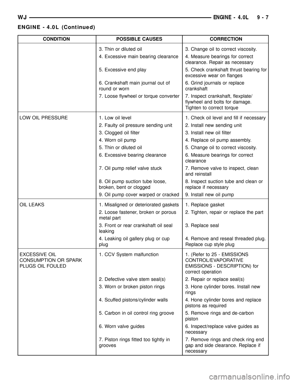
CONDITION POSSIBLE CAUSES CORRECTION
3. Thin or diluted oil 3. Change oil to correct viscosity.
4. Excessive main bearing clearance 4. Measure bearings for correct
clearance. Repair as necessary
5. Excessive end play 5. Check crankshaft thrust bearing for
excessive wear on flanges
6. Crankshaft main journal out of
round or worn6. Grind journals or replace
crankshaft
7. Loose flywheel or torque converter 7. Inspect crankshaft, flexplate/
flywheel and bolts for damage.
Tighten to correct torque
LOW OIL PRESSURE 1. Low oil level 1. Check oil level and fill if necessary
2. Faulty oil pressure sending unit 2. Install new sending unit
3. Clogged oil filter 3. Install new oil filter
4. Worn oil pump 4. Replace oil pump assembly.
5. Thin or diluted oil 5. Change oil to correct viscosity.
6. Excessive bearing clearance 6. Measure bearings for correct
clearance
7. Oil pump relief valve stuck 7. Remove valve to inspect, clean
and reinstall
8. Oil pump suction tube loose,
broken, bent or clogged8. Inspect suction tube and clean or
replace if necessary
9. Oil pump cover warped or cracked 9. Install new oil pump
OIL LEAKS 1. Misaligned or deteriorated gaskets 1. Replace gasket
2. Loose fastener, broken or porous
metal part2. Tighten, repair or replace the part
3. Front or rear crankshaft oil seal
leaking3. Replace seal
4. Leaking oil gallery plug or cup
plug4. Remove and reseal threaded plug.
Replace cup style plug
EXCESSIVE OIL
CONSUMPTION OR SPARK
PLUGS OIL FOULED1. CCV System malfunction 1. (Refer to 25 - EMISSIONS
CONTROL/EVAPORATIVE
EMISSIONS - DESCRIPTION) for
correct operation
2. Defective valve stem seal(s) 2. Repair or replace seal(s)
3. Worn or broken piston rings 3. Hone cylinder bores. Install new
rings
4. Scuffed pistons/cylinder walls 4. Hone cylinder bores and replace
pistons as required
5. Carbon in oil control ring groove 5. Remove rings and de-carbon
piston
6. Worn valve guides 6. Inspect/replace valve guides as
necessary
7. Piston rings fitted too tightly in
grooves7. Remove rings and check ring end
gap and side clearance. Replace if
necessary
WJENGINE - 4.0L 9 - 7
ENGINE - 4.0L (Continued)
Page 1421 of 2199
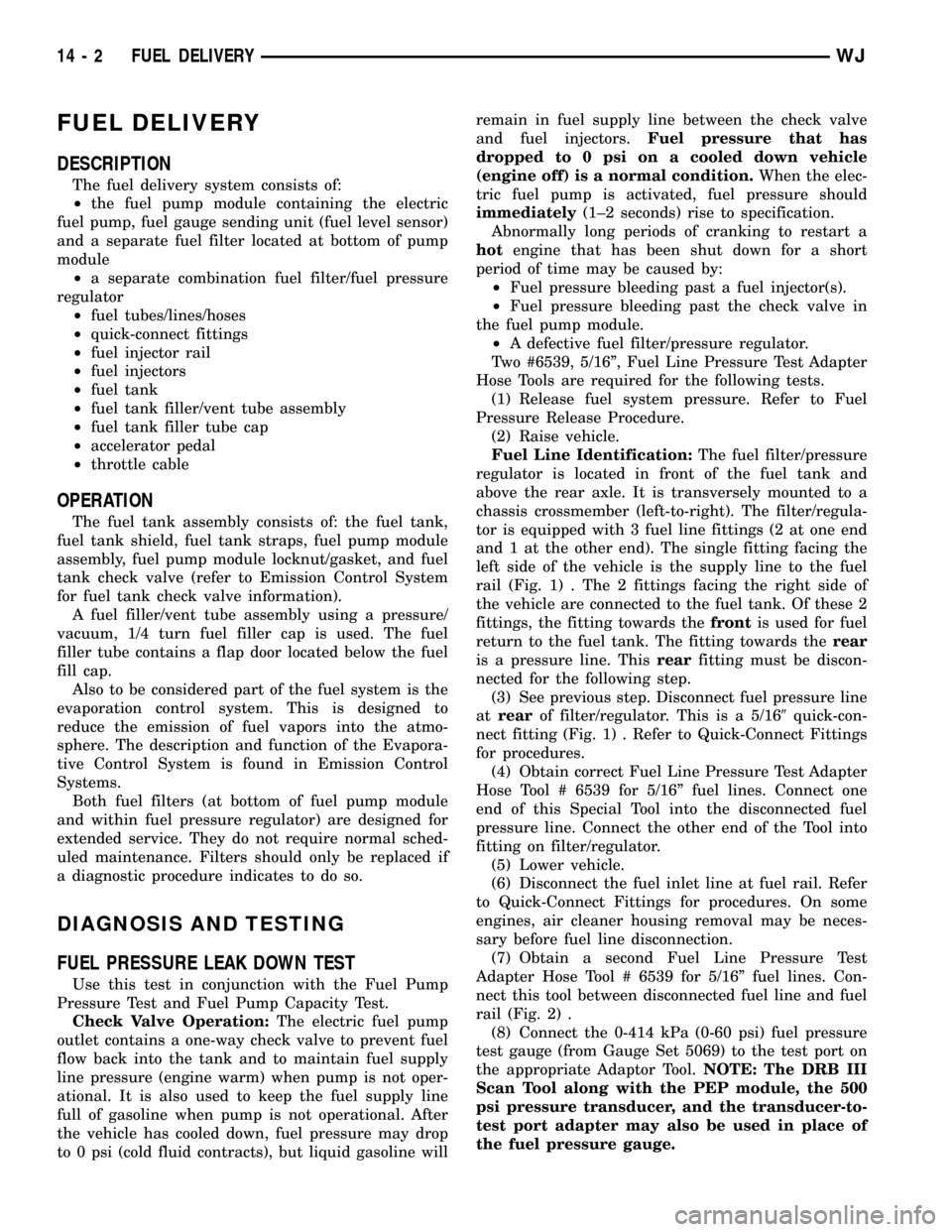
FUEL DELIVERY
DESCRIPTION
The fuel delivery system consists of:
²the fuel pump module containing the electric
fuel pump, fuel gauge sending unit (fuel level sensor)
and a separate fuel filter located at bottom of pump
module
²a separate combination fuel filter/fuel pressure
regulator
²fuel tubes/lines/hoses
²quick-connect fittings
²fuel injector rail
²fuel injectors
²fuel tank
²fuel tank filler/vent tube assembly
²fuel tank filler tube cap
²accelerator pedal
²throttle cable
OPERATION
The fuel tank assembly consists of: the fuel tank,
fuel tank shield, fuel tank straps, fuel pump module
assembly, fuel pump module locknut/gasket, and fuel
tank check valve (refer to Emission Control System
for fuel tank check valve information).
A fuel filler/vent tube assembly using a pressure/
vacuum, 1/4 turn fuel filler cap is used. The fuel
filler tube contains a flap door located below the fuel
fill cap.
Also to be considered part of the fuel system is the
evaporation control system. This is designed to
reduce the emission of fuel vapors into the atmo-
sphere. The description and function of the Evapora-
tive Control System is found in Emission Control
Systems.
Both fuel filters (at bottom of fuel pump module
and within fuel pressure regulator) are designed for
extended service. They do not require normal sched-
uled maintenance. Filters should only be replaced if
a diagnostic procedure indicates to do so.
DIAGNOSIS AND TESTING
FUEL PRESSURE LEAK DOWN TEST
Use this test in conjunction with the Fuel Pump
Pressure Test and Fuel Pump Capacity Test.
Check Valve Operation:The electric fuel pump
outlet contains a one-way check valve to prevent fuel
flow back into the tank and to maintain fuel supply
line pressure (engine warm) when pump is not oper-
ational. It is also used to keep the fuel supply line
full of gasoline when pump is not operational. After
the vehicle has cooled down, fuel pressure may drop
to 0 psi (cold fluid contracts), but liquid gasoline willremain in fuel supply line between the check valve
and fuel injectors.Fuel pressure that has
dropped to 0 psi on a cooled down vehicle
(engine off) is a normal condition.When the elec-
tric fuel pump is activated, fuel pressure should
immediately(1±2 seconds) rise to specification.
Abnormally long periods of cranking to restart a
hotengine that has been shut down for a short
period of time may be caused by:
²Fuel pressure bleeding past a fuel injector(s).
²Fuel pressure bleeding past the check valve in
the fuel pump module.
²A defective fuel filter/pressure regulator.
Two #6539, 5/16º, Fuel Line Pressure Test Adapter
Hose Tools are required for the following tests.
(1) Release fuel system pressure. Refer to Fuel
Pressure Release Procedure.
(2) Raise vehicle.
Fuel Line Identification:The fuel filter/pressure
regulator is located in front of the fuel tank and
above the rear axle. It is transversely mounted to a
chassis crossmember (left-to-right). The filter/regula-
tor is equipped with 3 fuel line fittings (2 at one end
and 1 at the other end). The single fitting facing the
left side of the vehicle is the supply line to the fuel
rail (Fig. 1) . The 2 fittings facing the right side of
the vehicle are connected to the fuel tank. Of these 2
fittings, the fitting towards thefrontis used for fuel
return to the fuel tank. The fitting towards therear
is a pressure line. Thisrearfitting must be discon-
nected for the following step.
(3) See previous step. Disconnect fuel pressure line
atrearof filter/regulator. This is a 5/169quick-con-
nect fitting (Fig. 1) . Refer to Quick-Connect Fittings
for procedures.
(4) Obtain correct Fuel Line Pressure Test Adapter
Hose Tool # 6539 for 5/16º fuel lines. Connect one
end of this Special Tool into the disconnected fuel
pressure line. Connect the other end of the Tool into
fitting on filter/regulator.
(5) Lower vehicle.
(6) Disconnect the fuel inlet line at fuel rail. Refer
to Quick-Connect Fittings for procedures. On some
engines, air cleaner housing removal may be neces-
sary before fuel line disconnection.
(7) Obtain a second Fuel Line Pressure Test
Adapter Hose Tool # 6539 for 5/16º fuel lines. Con-
nect this tool between disconnected fuel line and fuel
rail (Fig. 2) .
(8) Connect the 0-414 kPa (0-60 psi) fuel pressure
test gauge (from Gauge Set 5069) to the test port on
the appropriate Adaptor Tool.NOTE: The DRB III
Scan Tool along with the PEP module, the 500
psi pressure transducer, and the transducer-to-
test port adapter may also be used in place of
the fuel pressure gauge.
14 - 2 FUEL DELIVERYWJ
Page 1425 of 2199
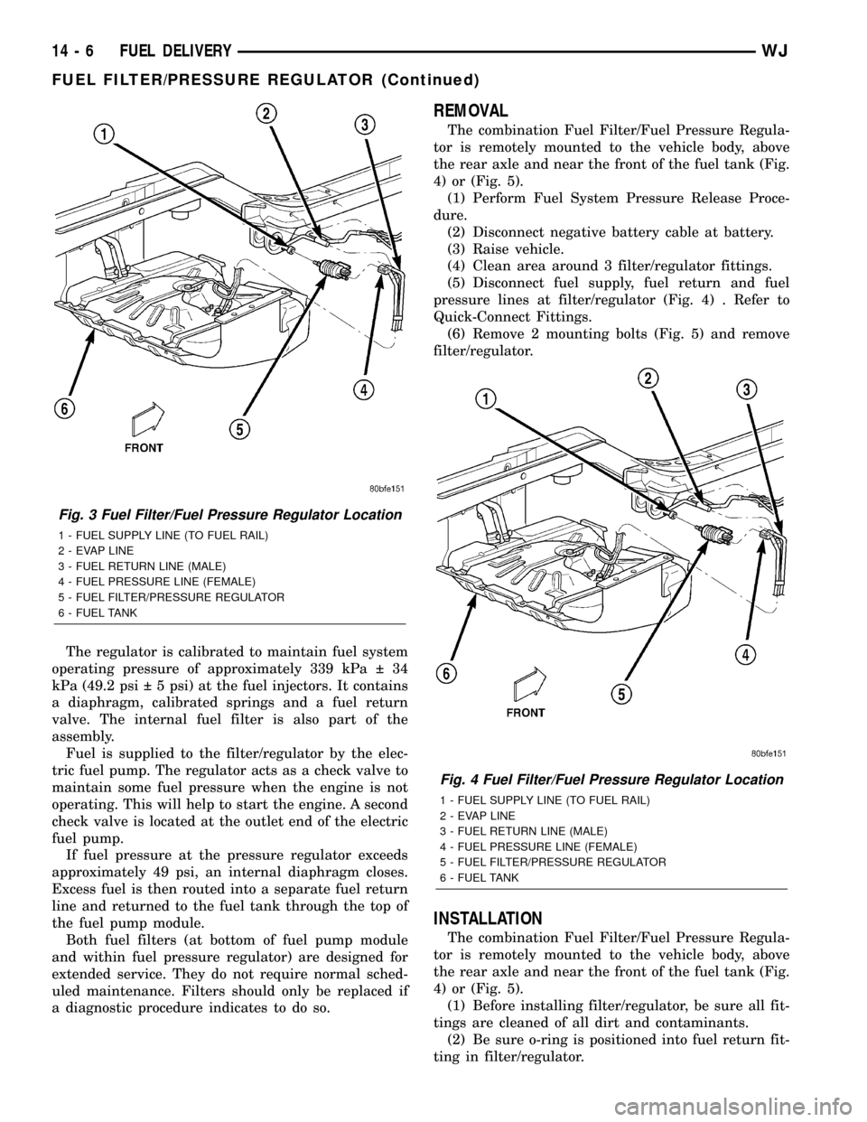
The regulator is calibrated to maintain fuel system
operating pressure of approximately 339 kPa 34
kPa (49.2 psi 5 psi) at the fuel injectors. It contains
a diaphragm, calibrated springs and a fuel return
valve. The internal fuel filter is also part of the
assembly.
Fuel is supplied to the filter/regulator by the elec-
tric fuel pump. The regulator acts as a check valve to
maintain some fuel pressure when the engine is not
operating. This will help to start the engine. A second
check valve is located at the outlet end of the electric
fuel pump.
If fuel pressure at the pressure regulator exceeds
approximately 49 psi, an internal diaphragm closes.
Excess fuel is then routed into a separate fuel return
line and returned to the fuel tank through the top of
the fuel pump module.
Both fuel filters (at bottom of fuel pump module
and within fuel pressure regulator) are designed for
extended service. They do not require normal sched-
uled maintenance. Filters should only be replaced if
a diagnostic procedure indicates to do so.
REMOVAL
The combination Fuel Filter/Fuel Pressure Regula-
tor is remotely mounted to the vehicle body, above
the rear axle and near the front of the fuel tank (Fig.
4) or (Fig. 5).
(1) Perform Fuel System Pressure Release Proce-
dure.
(2) Disconnect negative battery cable at battery.
(3) Raise vehicle.
(4) Clean area around 3 filter/regulator fittings.
(5) Disconnect fuel supply, fuel return and fuel
pressure lines at filter/regulator (Fig. 4) . Refer to
Quick-Connect Fittings.
(6) Remove 2 mounting bolts (Fig. 5) and remove
filter/regulator.
INSTALLATION
The combination Fuel Filter/Fuel Pressure Regula-
tor is remotely mounted to the vehicle body, above
the rear axle and near the front of the fuel tank (Fig.
4) or (Fig. 5).
(1) Before installing filter/regulator, be sure all fit-
tings are cleaned of all dirt and contaminants.
(2) Be sure o-ring is positioned into fuel return fit-
ting in filter/regulator.
Fig. 3 Fuel Filter/Fuel Pressure Regulator Location
1 - FUEL SUPPLY LINE (TO FUEL RAIL)
2 - EVAP LINE
3 - FUEL RETURN LINE (MALE)
4 - FUEL PRESSURE LINE (FEMALE)
5 - FUEL FILTER/PRESSURE REGULATOR
6 - FUEL TANK
Fig. 4 Fuel Filter/Fuel Pressure Regulator Location
1 - FUEL SUPPLY LINE (TO FUEL RAIL)
2 - EVAP LINE
3 - FUEL RETURN LINE (MALE)
4 - FUEL PRESSURE LINE (FEMALE)
5 - FUEL FILTER/PRESSURE REGULATOR
6 - FUEL TANK
14 - 6 FUEL DELIVERYWJ
FUEL FILTER/PRESSURE REGULATOR (Continued)