2003 JEEP GRAND CHEROKEE 5 volt supply wiring diagram
[x] Cancel search: 5 volt supply wiring diagramPage 379 of 2199

HEATED MIRRORS
TABLE OF CONTENTS
page page
HEATED MIRRORS
DESCRIPTION..........................8
OPERATION............................8DIAGNOSIS AND TESTING - HEATED
MIRRORS............................8
HEATED MIRRORS
DESCRIPTION
Electrically heated outside rear view mirrors are
optional equipment on this model. These mirrors fea-
ture an electric heating grid located behind the mir-
ror glass of each power operated outside rear view
mirror. These heating grids consist of a single resis-
tor wire routed in a grid-like pattern and captured
between two thin sheets of plastic. When electrical
current is passed through the resistor wire, it pro-
duces enough heat energy to clear the outside mirror
glass of ice, snow or fog. Battery current is directed
to the outside mirror heating grid only when the rear
window defogger switch is in the On position.
If the outside mirror heating grids and the rear
window heating grid are all inoperative, (Refer to 8 -
ELECTRICAL/HEATED GLASS - DIAGNOSIS AND
TESTING - REAR WINDOW DEFOGGER SYSTEM).
If the outside mirror heating grids are inoperative,
but the rear window heating grid is operating as
designed, (Refer to 8 - ELECTRICAL/HEATED MIR-
RORS - DIAGNOSIS AND TESTING)
The heating grid behind each outside mirror glass
cannot be repaired and, if faulty or damaged, the
entire power mirror unit must be replaced. Refer to
Power Mirrors for the procedures.
OPERATION
The outside mirror heating grids are energized and
de-energized by the Driver Door Module (DDM) and
the Passenger Door Module (PDM) based upon the
rear window defogger switch status. The Body Con-
trol Module (BCM) monitors the rear window defog-ger switch. When the BCM receives an input from
the switch, it sends a defogger switch status message
to the DDM and the PDM over the Programmable
Communications Interface data bus. The DDM and
PDM respond to the defogger switch status messages
by energizing or de-energizing the battery current
feed to their respective outside rear view mirror
heating grids.
DIAGNOSIS AND TESTING - HEATED MIRRORS
For circuit descriptions and diagrams, (Refer to
Appropriate Wiring Information).
(1) If both mirror heaters are inoperative, check
for proper operation of the Rear Window Defogger
System. (Refer to 8 - ELECTRICAL/HEATED GLASS
- DIAGNOSIS AND TESTING - REAR WINDOW
DEFOGGER SYSTEM). If Rear Window Defogger
System operates correctly, or if only one mirror
heater is inoperative, go to Step 2.
(2) Disconnect and isolate the battery negative
cable. Remove the front door trim panel on the side
of the inoperative mirror heater. Go to Step 3.
(3) Disconnect the door wire harness connector
from the door module connector receptacle. Check for
continuity between the mirror heater 12 volt supply,
and the mirror heater ground. There should be con-
tinuity. If OK, go to Step 4. If not OK, check for con-
tinuity of the individual circuits between the power
mirror and the door module, and of the mirror heater
grid right at the power mirror.
(4) Use a DRB IIItand (Refer to Appropriate
Diagnostic Information) to test the door module and
the PCI data bus.
8G - 8 HEATED MIRRORSWJ
Page 386 of 2199

HEATED SEAT SENSOR
DESCRIPTION
The heated seat temperature sensor is a Negative
Temperature Coefficient (NTC) thermistor. One tem-
perature sensor is used for each seat. This tempera-
ture sensor is located in the seat cushion heating
element on all models.
The heated seat temperature sensor cannot be
repaired or adjusted and must be replaced if defec-
tive. The heated seat cushion element must be
replaced if the temperature sensor is defective. Refer
to the procedure in this section of the service man-
ual.
DIAGNOSIS AND TESTING - HEATED SEAT
SENSOR
For complete circuit diagrams, refer toWiring
Diagrams.
(1) Disconnect the Heated Seat Module (HSM) or
Memory Heated Seat Module (MHSM) C1 connector.
Check for continuity between the SEAT SENSOR 5V
SUPPLY circuit cavity and the seat cushion frame.
There should beNOcontinuity. If OK, go to Step 2.
If not OK, repair the shorted seat sensor 5V supply
circuit as required.
(2) Check for continuity between the SEAT SEN-
SOR 5V SUPPLY circuit cavity of the 4-way power
seat wire harness connector and the C1 connector for
the HSM or MHSM. There should be continuity. If
OK, go to Step 3. If not OK, repair the open seat sen-
sor 5V supply circuit as required.
(3) Connect the module electrical connector. Turn
system ON, using a voltmeter, backprobe the HSM or
MHSM C1 connector on the SEAT TEMPERATURE
SENSOR INPUT circuit cavity. Voltage should be
present (2-4 volts). If OK, proceed with testing the
other components in the heated seat system. If not
OK, refer to Heated Seat Module Diagnosis and Test-
ing in the electronic control modules section of this
manual.
REMOVAL
(1) For heated seat sensor replacement procedure
(Refer to 8 - ELECTRICAL/HEATED SEATS/
HEATED SEAT ELEMENT - REMOVAL).
PASSENGER HEATED SEAT
SWITCH
DESCRIPTION
The heated seat switches are mounted in the
instrument panel center lower bezel (Fig. 7), which is
located near the bottom of the instrument panel cen-
ter stack. The two three-position rocker-type
switches, one switch for each front seat, provide a
resistor multiplexed signal to the Body Control Mod-
ule (BCM) through separate hard wired circuits.
Each switch has an Off, Low, and High position so
that both the driver and the front seat passenger can
select a preferred seat heating mode. Each switch
has two Light-Emitting Diodes (LED), one each for
the Low position and the High position, which light
to indicate that the heater for the seat that the
switch controls is turned on. Each switch is also back
lit by a replaceable incandescent bulb.
The heated seat switches and their LEDs cannot
be repaired. If either switch or LED is faulty or dam-
aged, the entire switch unit must be replaced. The
incandescent switch illumination bulb and bulb
holder units are available for service replacement.
Fig. 7 HEATED SEAT SWITCHES
1 - HEATED SEAT SWITCHES
WJHEATED SEAT SYSTEM 8G - 15
Page 422 of 2199
an input from the auto headlamp light sensor to
determine the ambient light levels. If the BCM
decides that the exterior lighting is turned on in the
daylight, it overrides the selected panel dimmer
switch signal by sending a message over the PCI
data bus to illuminate all vacuum fluorescent dis-
plays at full brightness for improved visibility in day-
time light levels. The automatic parade mode has no
effect on the incandescent bulb illumination intensity.
The hard wired cluster illumination circuits
between the left (lighting) multi-function switch and
the BCM may be diagnosed using conventional diag-
nostic tools and methods. The electro-luminescent
lamp is diagnosed using the EMIC self-diagnostic
actuator test. (Refer to 8 - ELECTRICAL/INSTRU-
MENT CLUSTER - DIAGNOSIS AND TESTING).
However, proper testing of the EMIC and the elec-
tronic dimming level messages sent by the BCM over
the PCI data bus requires the use of a DRBIIItscan
tool. Refer to the appropriate diagnostic information.
CHIME SERVICE
The EMIC is programmed to request chime service
from the Body Control Module (BCM) when certain
indicators are illuminated. The EMIC chime request
for illumination of the low fuel indicator is a cus-
tomer programmable feature. When the programmed
conditions are met, the EMIC generates an electronic
chime request message and sends it over the PCI
data bus to the BCM. Upon receiving the proper
chime request, the BCM activates an integral chime
tone generator to provide the audible chime tone to
the vehicle operator. (Refer to 8 - ELECTRICAL/
CHIME WARNING SYSTEM - OPERATION). Proper
testing of the PCI data bus and the electronic chime
request message outputs from the EMIC requires the
use of a DRBIIItscan tool. Refer to the appropriate
diagnostic information.
DIAGNOSIS AND TESTING - INSTRUMENT
CLUSTER
If all of the instrument cluster gauges and/or indi-
cators are inoperative, refer to PRELIMINARY
DIAGNOSIS . If an individual gauge or Programma-
ble Communications Interface (PCI) data bus mes-
sage-controlled indicator is inoperative, refer to
ACTUATOR TEST . If an individual hard wired indi-
cator is inoperative, refer to the diagnosis and testing
information for that specific indicator. If the base
instrument cluster incandescent illumination lighting
is inoperative, refer to CLUSTER ILLUMINATION
DIAGNOSIS . If the premium instrument cluster
electro-luminescent illumination lighting is inopera-
tive, refer to ACTUATOR TEST . Refer to the appro-
priate wiring information. The wiring information
includes wiring diagrams, proper wire and connectorrepair procedures, details of wire harness routing
and retention, connector pin-out information and
location views for the various wire harness connec-
tors, splices and grounds.
NOTE: Occasionally, a condition may be encoun-
tered where the gauge pointer for the speedometer
or the tachometer becomes caught on the wrong
side of the pointer stop. To correct this condition,
the technician should use a DRBIIITscan tool and
the appropriate diagnostic information to perform
the instrument cluster self-diagnostic actuator test
procedure. When performed, the actuator test pro-
cedure will automatically return the pointer to the
correct side of the pointer stop.
PRELIMINARY DIAGNOSIS
WARNING: ON VEHICLES EQUIPPED WITH AIR-
BAGS, DISABLE THE SUPPLEMENTAL RESTRAINT
SYSTEM BEFORE ATTEMPTING ANY STEERING
WHEEL, STEERING COLUMN, DRIVER AIRBAG,
PASSENGER AIRBAG, SIDE CURTAIN AIRBAG,
FRONT IMPACT SENSOR, SIDE IMPACT SENSOR,
OR INSTRUMENT PANEL COMPONENT DIAGNOSIS
OR SERVICE. DISCONNECT AND ISOLATE THE
BATTERY NEGATIVE (GROUND) CABLE, THEN
WAIT TWO MINUTES FOR THE SYSTEM CAPACI-
TOR TO DISCHARGE BEFORE PERFORMING FUR-
THER DIAGNOSIS OR SERVICE. THIS IS THE ONLY
SURE WAY TO DISABLE THE SUPPLEMENTAL
RESTRAINT SYSTEM. FAILURE TO TAKE THE
PROPER PRECAUTIONS COULD RESULT IN ACCI-
DENTAL AIRBAG DEPLOYMENT AND POSSIBLE
PERSONAL INJURY.
WARNING: ON VEHICLES EQUIPPED WITH THE
PREMIUM INSTRUMENT CLUSTER, THE CLUSTER
CIRCUITRY PROVIDES AN ALTERNATING CURRENT
TO SUPPLY POWER TO THE ELECTRO-LUMINES-
CENT ILLUMINATION LAMP THROUGH A PIGTAIL
WIRE AND CONNECTOR THAT IS ACCESSIBLE AT
THE BACK OF THE CLUSTER HOUSING. USE
PROPER PRECAUTIONS WHEN HANDLING THIS
UNIT DURING DIAGNOSIS OR SERVICE TO AVOID
ELECTRICAL SHOCK AND POSSIBLE PERSONAL
INJURY.
(1) Check the fused B(+) fuse (Fuse 17 - 10
ampere) in the Junction Block (JB). If OK, go to Step
2. If not OK, repair the shorted circuit or component
as required and replace the faulty fuse.
(2) Check for battery voltage at the fused B(+) fuse
(Fuse 17 - 10 ampere) in the JB. If OK, go to Step 3.
If not OK, repair the open fused B(+) circuit between
WJINSTRUMENT CLUSTER 8J - 7
INSTRUMENT CLUSTER (Continued)
Page 513 of 2199

DIAGNOSIS AND TESTING - SIDEVIEW
MIRROR
For complete circuit diagrams, refer to the appro-
priate wiring information. The wiring information
includes wiring diagrams, proper wire and connector
repair procedures, details of wire harness routing
and retention, connector pin-out information and
location views for the various wire harness connec-
tors, splices and grounds.
BOTH MIRRORS INOPERATIVE
(1) Check the operation of the power lock switch
on the driver side front door. If all of the doors lock
and unlock, replace the faulty Driver Door Module
(DDM). If not OK, go to Step 2.
(2) Check the operation of the power lock switch
on the passenger side front door. If all of the doors
lock and unlock, replace the faulty DDM. If not OK,
go to Step 3.
(3) Check the fused B(+) fuse in the Power Distri-
bution Center (PDC). If OK, go to Step 4. If not OK,
repair the shorted circuit or component as required
and replace the faulty fuse.
(4) Check for battery voltage at the fused B(+) fuse
in the PDC. If OK, go to Step 5. If not OK, repair the
open fused B(+) circuit to the battery as required.
(5) Disconnect and isolate the battery negative
cable. Remove the trim panel from the driver side
front door. Disconnect the 15-way door wire harness
connector from the DDM connector receptacle. Check
for continuity between the ground circuit cavity of
the 15-way door wire harness connector for the DDM
and a good ground. There should be continuity. If
OK, go to Step 6. If not OK, repair the open ground
circuit to ground as required.
(6)
Reconnect the battery negative cable. Check for
battery voltage at the fused B(+) circuit cavity of the
15-way door wire harness connector for the DDM. If
OK, replace the faulty DDM. If not OK, repair the open
fused B(+) circuit to the fuse in the PDC as required.
ONE MIRROR INOPERATIVE
(1) If the one inoperative mirror is on the passen-
ger side, go to Step 2. If the one inoperative mirror is
on the driver side, go to Step 3.
(2)
Check if the passenger front door will lock and
unlock using the power lock switch on the driver side
front door. If OK, go to Step 3. If not OK, go to Step 6.
(3) Disconnect and isolate the battery negative
cable. Remove the trim panel from the front door.
Disconnect the 12-way mirror wire harness connector
from the door wire harness connector.
(4) Using two jumper wires, test the mirror as
shown in the Mirror Test chart (Fig. 2). If the mirror
tests OK, go to Step 5. If the mirror does not test
OK, replace the faulty mirror.(5) Disconnect the 12-way door wire harness con-
nector from the door module connector receptacle.
Check all of the circuits of the door wire harness
between the connector for the mirror and the connec-
tor for the door module for opens or shorts. If all of
the circuits are OK, replace the faulty door module.
If any of the circuits are not OK, repair the open or
shorted circuit(s) as required.
(6) Use a DRB scan tool and the proper Diagnostic
Procedures manual to test and repair the faulty Pro-
grammable Communications Interface (PCI) data bus
communication between the two door modules.
NO MIRROR HEAT
If one or both mirror heaters are inoperative,
(Refer to 8 - ELECTRICAL/HEATED MIRRORS -
DESCRIPTION).
(1) Disconnect and isolate the battery negative
cable. Remove the front door trim panel on the side
of the inoperative mirror heater.
(2) Disconnect the 12-way door wire harness con-
nector from the door module connector receptacle.
Check for continuity between the heater switched
ground circuit cavity and the heater 12V supply cir-
cuit cavity of the 12-way door wire harness connector
Fig. 2 Mirror Test
POWER MIRROR TEST TABLE
APPLY 12
VOLTS TO:APPLY
GROUND TO:MIRROR
REACTION
DRIVER SIDE
1 7 LEFT
7 1 RIGHT
87UP
7 8 DOWN
PASSENGER SIDE
1 7 LEFT
7 1 RIGHT
87UP
7 8 DOWN
8N - 16 POWER MIRRORSWJ
SIDEVIEW MIRROR (Continued)
Page 665 of 2199
STANDARD PROCEDURE - TESTING FOR A
SHORT TO GROUND ON FUSES POWERING
SEVERAL LOADS
(1) Refer to the wiring diagrams and disconnect or
isolate all items on the suspected fused circuits.
(2) Replace the blown fuse.
(3) Supply power to the fuse by turning ON the
ignition switch or re-connecting the battery.
(4) Start connecting or energizing the items in the
fuse circuit one at a time. When the fuse blows the
circuit with the short to ground has been isolated.
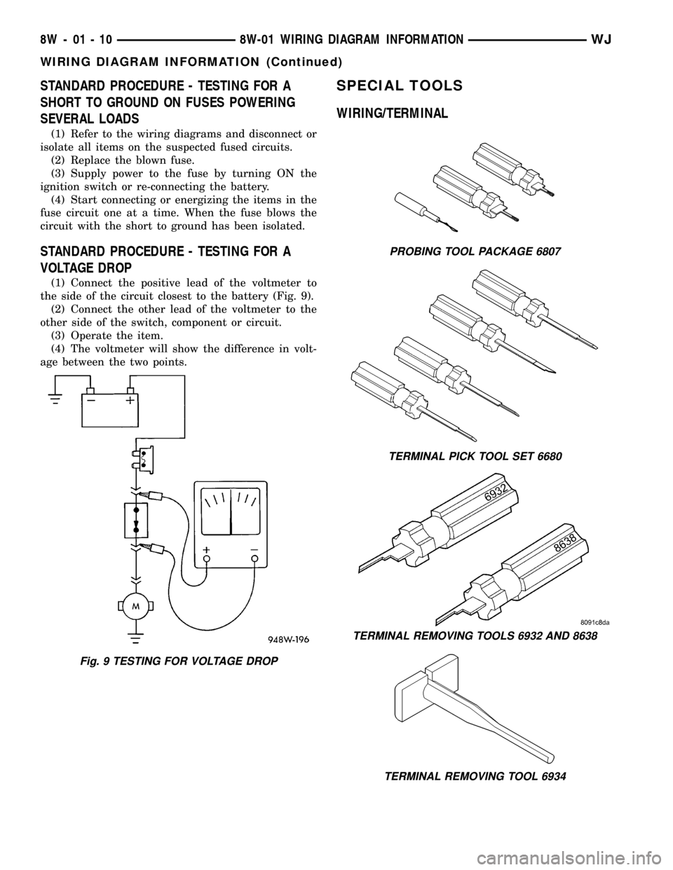
STANDARD PROCEDURE - TESTING FOR A
VOLTAGE DROP
(1) Connect the positive lead of the voltmeter to
the side of the circuit closest to the battery (Fig. 9).
(2) Connect the other lead of the voltmeter to the
other side of the switch, component or circuit.
(3) Operate the item.
(4) The voltmeter will show the difference in volt-
age between the two points.
SPECIAL TOOLS
WIRING/TERMINAL
Fig. 9 TESTING FOR VOLTAGE DROP
PROBING TOOL PACKAGE 6807
TERMINAL PICK TOOL SET 6680
TERMINAL REMOVING TOOLS 6932 AND 8638
TERMINAL REMOVING TOOL 6934
8W - 01 - 10 8W-01 WIRING DIAGRAM INFORMATIONWJ
WIRING DIAGRAM INFORMATION (Continued)
Page 1469 of 2199
The other two heater elements (downstream sen-
sors 1/2 and 2/2) are controlled by the downstream
heater relay through output signals from the PCM.
To avoid a large simultaneous current surge, power
is delayed to the 2 downstream heater elements by
the PCM for approximately 2 seconds.
REMOVAL
(1) Remove PDC cover.
(2) Remove relay from PDC.
(3) Check condition of relay terminals and PDC
connector terminals for damage or corrosion. Repair
if necessary before installing relay.
(4) Check for pin height (pin height should be the
same for all terminals within the PDC connector).
Repair if necessary before installing relay.
INSTALLATION
(1) Install relay to PDC.
(2) Install cover to PDC.
O2S SENSOR
DESCRIPTION
The Oxygen Sensors (O2S) are attached to, and
protrude into the vehicle exhaust system. Depending
on the emission package, the vehicle may use a total
of either 2 or 4 sensors.
Federal Emissions Package:Two sensors are
used: upstream (referred to as 1/1) and downstream
(referred to as 1/2). With this emission package, the
upstream sensor (1/1) is located just before the main
catalytic convertor. The downstream sensor (1/2) is
located just after the main catalytic convertor.
4.7L V-8 With California Emissions Package:
On this emissions package, 4 sensors are used: 2
upstream (referred to as 1/1 and 2/1) and 2 down-
stream (referred to as 1/2 and 2/2). With this emis-
sion package, the right upstream sensor (2/1) is
located in the right exhaust downpipe just before the
mini-catalytic convertor. The left upstream sensor
(1/1) is located in the left exhaust downpipe just
before the mini-catalytic convertor. The right down-
stream sensor (2/2) is located in the right exhaust
downpipe just after the mini-catalytic convertor, and
before the main catalytic convertor. The left down-
stream sensor (1/2) is located in the left exhaust
downpipe just after the mini-catalytic convertor, and
before the main catalytic convertor.
4.0L 6±Cylinder With California Emissions
Package:On this emissions package, 4 sensors are
used: 2 upstream (referred to as 1/1 and 2/1) and 2
downstream (referred to as 1/2 and 2/2). With this
emission package, the rear/upper upstream sensor
(2/1) is located in the exhaust downpipe just beforethe rear mini-catalytic convertor. The front/upper
upstream sensor (1/1) is located in the exhaust down-
pipe just before the front mini-catalytic convertor.
The rear/lower downstream sensor (2/2) is located in
the exhaust downpipe just after the rear mini-cata-
lytic convertor, and before the main catalytic conver-
tor. The front/lower downstream sensor (1/2) is
located in the exhaust downpipe just after the front
mini-catalytic convertor, and before the main cata-
lytic convertor.
OPERATION
An O2 sensor is a galvanic battery that provides
the PCM with a voltage signal (0-1 volt) inversely
proportional to the amount of oxygen in the exhaust.
In other words, if the oxygen content is low, the volt-
age output is high; if the oxygen content is high the
output voltage is low. The PCM uses this information
to adjust injector pulse-width to achieve the
14.7±to±1 air/fuel ratio necessary for proper engine
operation and to control emissions.
The O2 sensor must have a source of oxygen from
outside of the exhaust stream for comparison. Cur-
rent O2 sensors receive their fresh oxygen (outside
air) supply through the O2 sensor case housing.
Four wires (circuits) are used on each O2 sensor: a
12±volt feed circuit for the sensor heating element; a
ground circuit for the heater element; a low-noise
sensor return circuit to the PCM, and an input cir-
cuit from the sensor back to the PCM to detect sen-
sor operation.
Oxygen Sensor Heaters/Heater Relays:
Depending on the emissions package, the heating ele-
ments within the sensors will be supplied voltage
from either the ASD relay, or 2 separate oxygen sen-
sor relays. Refer to Wiring Diagrams to determine
which relays are used.
The O2 sensor uses a Positive Thermal Co-efficient
(PTC) heater element. As temperature increases,
resistance increases. At ambient temperatures
around 70ÉF, the resistance of the heating element is
approximately 4.5 ohms on 4.0L engines. It is
approximately 13.5 ohms on the 4.7L engine. As the
sensor's temperature increases, resistance in the
heater element increases. This allows the heater to
maintain the optimum operating temperature of
approximately 930É-1100ÉF (500É-600É C). Although
the sensors operate the same, there are physical dif-
ferences, due to the environment that they operate
in, that keep them from being interchangeable.
Maintaining correct sensor temperature at all
times allows the system to enter into closed loop
operation sooner. Also, it allows the system to remain
in closed loop operation during periods of extended
idle.
14 - 50 FUEL INJECTIONWJ
O2S HEATER RELAY (Continued)