2003 JEEP GRAND CHEROKEE turn relay
[x] Cancel search: turn relayPage 1161 of 2199
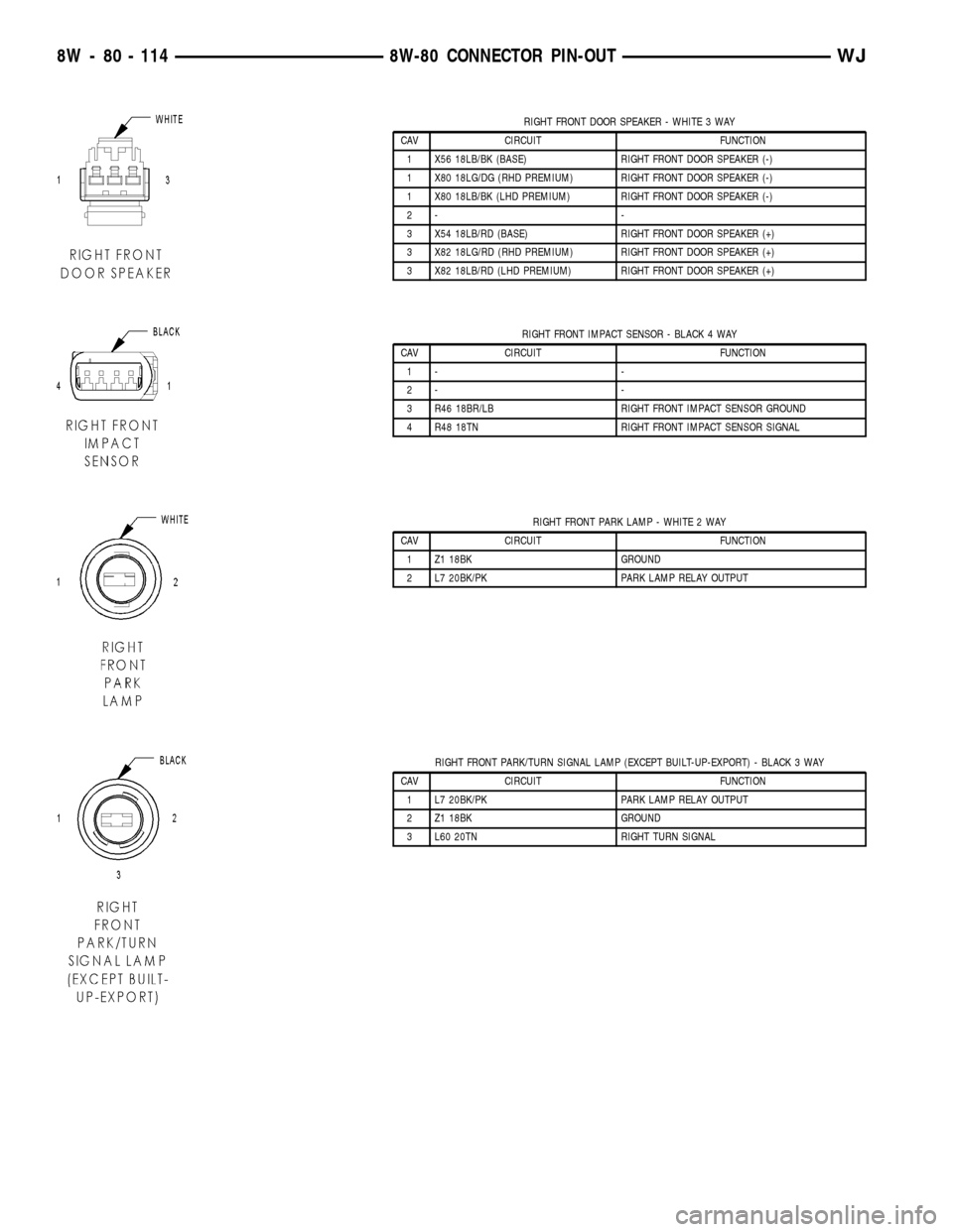
RIGHT FRONT DOOR SPEAKER - WHITE 3 WAY
CAV CIRCUIT FUNCTION
1 X56 18LB/BK (BASE) RIGHT FRONT DOOR SPEAKER (-)
1 X80 18LG/DG (RHD PREMIUM) RIGHT FRONT DOOR SPEAKER (-)
1 X80 18LB/BK (LHD PREMIUM) RIGHT FRONT DOOR SPEAKER (-)
2- -
3 X54 18LB/RD (BASE) RIGHT FRONT DOOR SPEAKER (+)
3 X82 18LG/RD (RHD PREMIUM) RIGHT FRONT DOOR SPEAKER (+)
3 X82 18LB/RD (LHD PREMIUM) RIGHT FRONT DOOR SPEAKER (+)
RIGHT FRONT IMPACT SENSOR - BLACK 4 WAY
CAV CIRCUIT FUNCTION
1- -
2- -
3 R46 18BR/LB RIGHT FRONT IMPACT SENSOR GROUND
4 R48 18TN RIGHT FRONT IMPACT SENSOR SIGNAL
RIGHT FRONT PARK LAMP - WHITE 2 WAY
CAV CIRCUIT FUNCTION
1 Z1 18BK GROUND
2 L7 20BK/PK PARK LAMP RELAY OUTPUT
RIGHT FRONT PARK/TURN SIGNAL LAMP (EXCEPT BUILT-UP-EXPORT) - BLACK 3 WAY
CAV CIRCUIT FUNCTION
1 L7 20BK/PK PARK LAMP RELAY OUTPUT
2 Z1 18BK GROUND
3 L60 20TN RIGHT TURN SIGNAL
8W - 80 - 114 8W-80 CONNECTOR PIN-OUTWJ
Page 1162 of 2199
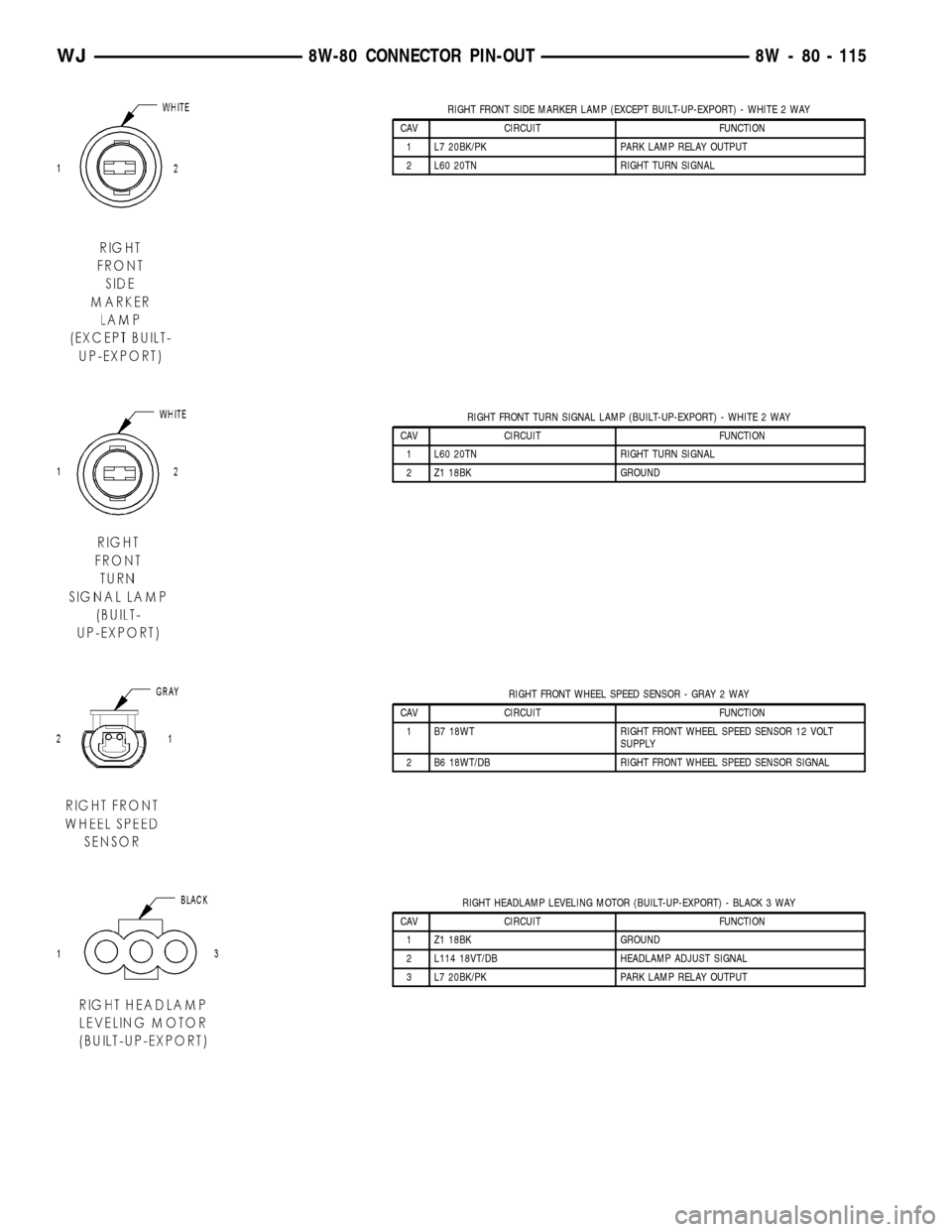
RIGHT FRONT SIDE MARKER LAMP (EXCEPT BUILT-UP-EXPORT) - WHITE 2 WAY
CAV CIRCUIT FUNCTION
1 L7 20BK/PK PARK LAMP RELAY OUTPUT
2 L60 20TN RIGHT TURN SIGNAL
RIGHT FRONT TURN SIGNAL LAMP (BUILT-UP-EXPORT) - WHITE 2 WAY
CAV CIRCUIT FUNCTION
1 L60 20TN RIGHT TURN SIGNAL
2 Z1 18BK GROUND
RIGHT FRONT WHEEL SPEED SENSOR - GRAY 2 WAY
CAV CIRCUIT FUNCTION
1 B7 18WT RIGHT FRONT WHEEL SPEED SENSOR 12 VOLT
SUPPLY
2 B6 18WT/DB RIGHT FRONT WHEEL SPEED SENSOR SIGNAL
RIGHT HEADLAMP LEVELING MOTOR (BUILT-UP-EXPORT) - BLACK 3 WAY
CAV CIRCUIT FUNCTION
1 Z1 18BK GROUND
2 L114 18VT/DB HEADLAMP ADJUST SIGNAL
3 L7 20BK/PK PARK LAMP RELAY OUTPUT
WJ8W-80 CONNECTOR PIN-OUT 8W - 80 - 115
Page 1164 of 2199
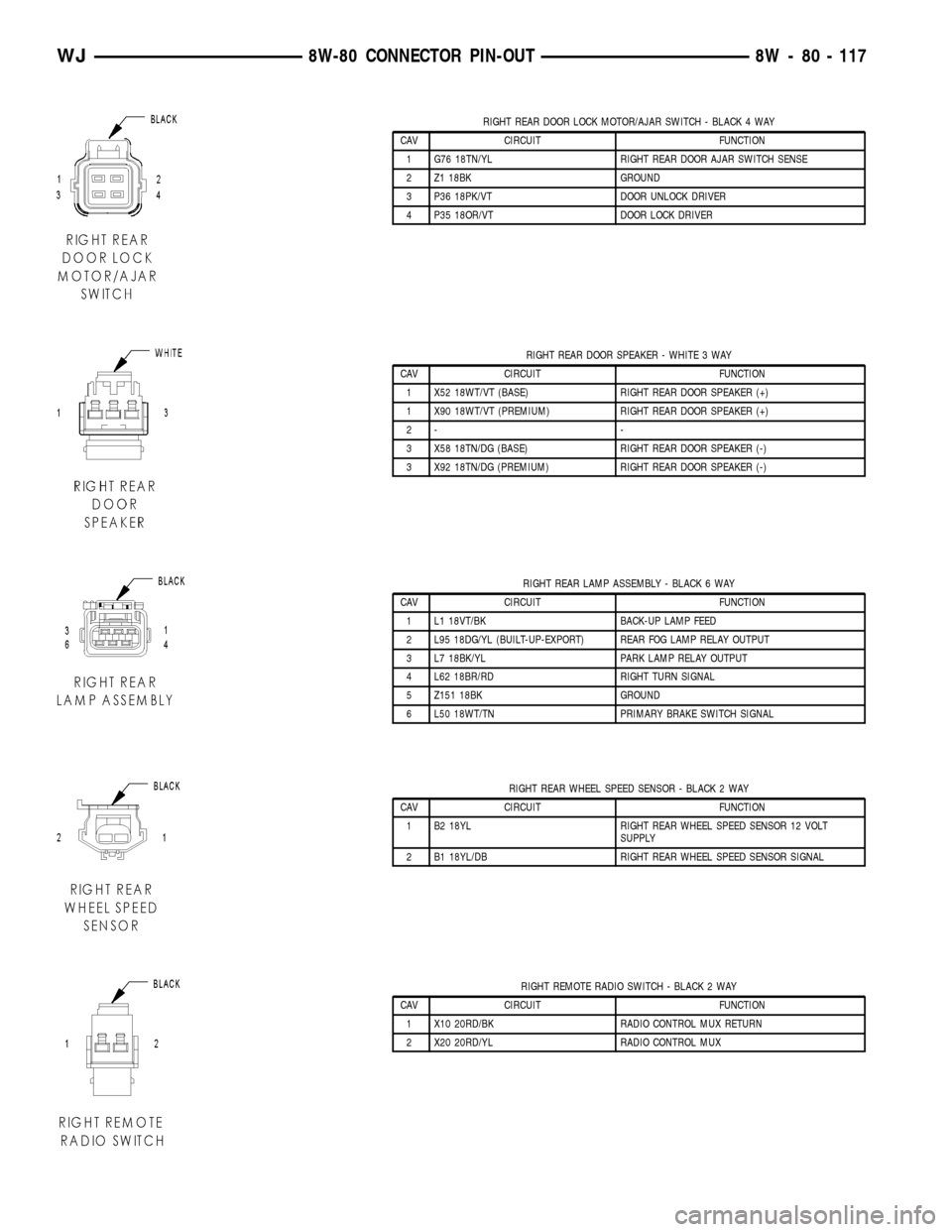
RIGHT REAR DOOR LOCK MOTOR/AJAR SWITCH - BLACK 4 WAY
CAV CIRCUIT FUNCTION
1 G76 18TN/YL RIGHT REAR DOOR AJAR SWITCH SENSE
2 Z1 18BK GROUND
3 P36 18PK/VT DOOR UNLOCK DRIVER
4 P35 18OR/VT DOOR LOCK DRIVER
RIGHT REAR DOOR SPEAKER - WHITE 3 WAY
CAV CIRCUIT FUNCTION
1 X52 18WT/VT (BASE) RIGHT REAR DOOR SPEAKER (+)
1 X90 18WT/VT (PREMIUM) RIGHT REAR DOOR SPEAKER (+)
2- -
3 X58 18TN/DG (BASE) RIGHT REAR DOOR SPEAKER (-)
3 X92 18TN/DG (PREMIUM) RIGHT REAR DOOR SPEAKER (-)
RIGHT REAR LAMP ASSEMBLY - BLACK 6 WAY
CAV CIRCUIT FUNCTION
1 L1 18VT/BK BACK-UP LAMP FEED
2 L95 18DG/YL (BUILT-UP-EXPORT) REAR FOG LAMP RELAY OUTPUT
3 L7 18BK/YL PARK LAMP RELAY OUTPUT
4 L62 18BR/RD RIGHT TURN SIGNAL
5 Z151 18BK GROUND
6 L50 18WT/TN PRIMARY BRAKE SWITCH SIGNAL
RIGHT REAR WHEEL SPEED SENSOR - BLACK 2 WAY
CAV CIRCUIT FUNCTION
1 B2 18YL RIGHT REAR WHEEL SPEED SENSOR 12 VOLT
SUPPLY
2 B1 18YL/DB RIGHT REAR WHEEL SPEED SENSOR SIGNAL
RIGHT REMOTE RADIO SWITCH - BLACK 2 WAY
CAV CIRCUIT FUNCTION
1 X10 20RD/BK RADIO CONTROL MUX RETURN
2 X20 20RD/YL RADIO CONTROL MUX
WJ8W-80 CONNECTOR PIN-OUT 8W - 80 - 117
Page 1170 of 2199
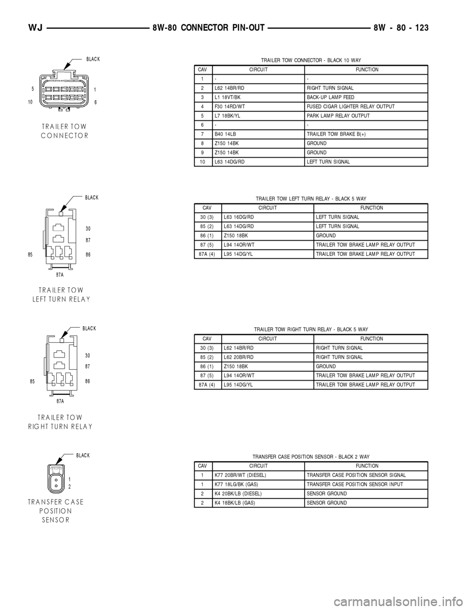
TRAILER TOW CONNECTOR - BLACK 10 WAY
CAV CIRCUIT FUNCTION
1- -
2 L62 14BR/RD RIGHT TURN SIGNAL
3 L1 18VT/BK BACK-UP LAMP FEED
4 F30 14RD/WT FUSED CIGAR LIGHTER RELAY OUTPUT
5 L7 18BK/YL PARK LAMP RELAY OUTPUT
6- -
7 B40 14LB TRAILER TOW BRAKE B(+)
8 Z150 14BK GROUND
9 Z150 14BK GROUND
10 L63 14DG/RD LEFT TURN SIGNAL
TRAILER TOW LEFT TURN RELAY - BLACK 5 WAY
CAV CIRCUIT FUNCTION
30 (3) L63 16DG/RD LEFT TURN SIGNAL
85 (2) L63 14DG/RD LEFT TURN SIGNAL
86 (1) Z150 18BK GROUND
87 (5) L94 14OR/WT TRAILER TOW BRAKE LAMP RELAY OUTPUT
87A (4) L95 14DG/YL TRAILER TOW BRAKE LAMP RELAY OUTPUT
TRAILER TOW RIGHT TURN RELAY - BLACK 5 WAY
CAV CIRCUIT FUNCTION
30 (3) L62 14BR/RD RIGHT TURN SIGNAL
85 (2) L62 20BR/RD RIGHT TURN SIGNAL
86 (1) Z150 18BK GROUND
87 (5) L94 14OR/WT TRAILER TOW BRAKE LAMP RELAY OUTPUT
87A (4) L95 14DG/YL TRAILER TOW BRAKE LAMP RELAY OUTPUT
TRANSFER CASE POSITION SENSOR - BLACK 2 WAY
CAV CIRCUIT FUNCTION
1 K77 20BR/WT (DIESEL) TRANSFER CASE POSITION SENSOR SIGNAL
1 K77 18LG/BK (GAS) TRANSFER CASE POSITION SENSOR INPUT
2 K4 20BK/LB (DIESEL) SENSOR GROUND
2 K4 18BK/LB (GAS) SENSOR GROUND
WJ8W-80 CONNECTOR PIN-OUT 8W - 80 - 123
Page 1186 of 2199
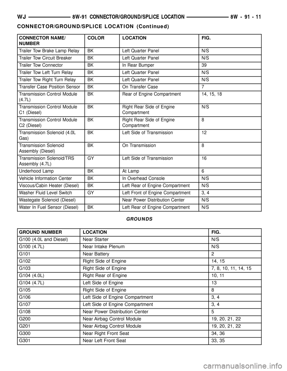
CONNECTOR NAME/
NUMBERCOLOR LOCATION FIG.
Trailer Tow Brake Lamp Relay BK Left Quarter Panel N/S
Trailer Tow Circuit Breaker BK Left Quarter Panel N/S
Trailer Tow Connector BK In Rear Bumper 39
Trailer Tow Left Turn Relay BK Left Quarter Panel N/S
Trailer Tow Right Turn Relay BK Left Quarter Panel N/S
Transfer Case Position Sensor BK On Transfer Case 7
Transmission Control Module
(4.7L)BK Rear of Engine Compartment 14, 15, 18
Transmission Control Module
C1 (Diesel)BK Right Rear Side of Engine
CompartmentN/S
Transmission Control Module
C2 (Diesel)BK Right Rear Side of Engine
Compartment8
Transmission Solenoid (4.0L
Gas)BK Left Side of Transmission 12
Transmission Solenoid
Assembly (Diesel)BK On Transmission 8
Transmission Solenoid/TRS
Assembly (4.7L)GY Left Side of Transmission 16
Underhood Lamp BK At Lamp 6
Vehicle Information Center BK In Overhead Console N/S
Viscous/Cabin Heater (Diesel) BK Left Rear of Engine Compartment N/S
Washer Fluid Level Switch GY Left Front of Engine Compartment 3, 4
Wastegate Solenoid (Diesel) Near Power Distribution Center N/S
Water In Fuel Sensor (Diesel) BK Left Rear of Engine Compartment N/S
GROUNDS
GROUND NUMBER LOCATION FIG.
G100 (4.0L and Diesel) Near Starter N/S
G100 (4.7L) Near Intake Plenum N/S
G101 Near Battery 2
G102 Right Side of Engine 14, 15
G103 Right Side of Engine 7, 8, 10, 11, 14, 15
G104 (4.0L) Right Rear of Engine 10, 11
G104 (4.7L) Left Side of Engine 13
G105 Right Side of Engine 8
G106 Left Side of Engine Compartment 3, 4
G107 Left Side of Engine Compartment 3, 4
G108 Near Power Distribution Center 5
G200 Near Airbag Control Module 19, 20, 21, 22
G201 Near Airbag Control Module 19, 20, 21, 22
G300 Near Right Front Seat 34, 36
G301 Near Left Front Seat 33, 35
WJ8W-91 CONNECTOR/GROUND/SPLICE LOCATION 8W - 91 - 11
CONNECTOR/GROUND/SPLICE LOCATION (Continued)
Page 1192 of 2199
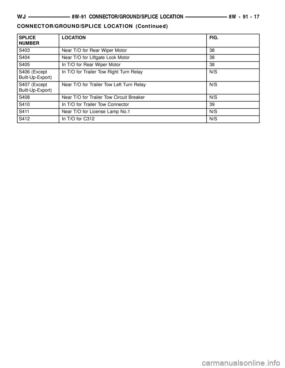
SPLICE
NUMBERLOCATION FIG.
S403 Near T/O for Rear Wiper Motor 38
S404 Near T/O for Liftgate Lock Motor 38
S405 In T/O for Rear Wiper Motor 38
S406 (Except
Built-Up-Export)In T/O for Trailer Tow Right Turn Relay N/S
S407 (Except
Built-Up-Export)Near T/O for Trailer Tow Left Turn Relay N/S
S408 Near T/O for Trailer Tow Circuit Breaker N/S
S410 In T/O for Trailer Tow Connector 39
S411 Near T/O for License Lamp No.1 N/S
S412 In T/O for C312 N/S
WJ8W-91 CONNECTOR/GROUND/SPLICE LOCATION 8W - 91 - 17
CONNECTOR/GROUND/SPLICE LOCATION (Continued)
Page 1229 of 2199

of the preparation procedures performed just prior to
new vehicle delivery.
The PDC has a molded plastic cover that can be
removed to provide service access to all of the fuses
and relays in the PDC. An integral latch and hinges
are molded into the PDC cover for easy removal. A
fuse layout map is integral to the underside of the
PDC cover to ensure proper fuse and relay identifica-
tion. The IOD fuse is a 50 ampere maxi-type car-
tridge fuse and, when removed, it is stored in a spare
fuse cavity within the PDC.
OPERATION
The term ignition-off draw identifies a normal con-
dition where power is being drained from the battery
with the ignition switch in the Off position. The IOD
fuse feeds the memory and sleep mode functions for
some of the electronic modules in the vehicle as well
as various other accessories that require battery cur-
rent when the ignition switch is in the Off position,
including the clock. The only reason the IOD fuse is
removed is to reduce the normal IOD of the vehicle
electrical system during new vehicle transportation
and pre-delivery storage to reduce battery depletion,
while still allowing vehicle operation so that the
vehicle can be loaded, unloaded and moved as needed
by both vehicle transportation company and dealer
personnel.
The IOD fuse is removed from PDC fuse cavity 15
when the vehicle is shipped from the assembly plant.
Dealer personnel must install the IOD fuse when the
vehicle is being prepared for delivery in order to
restore full electrical system operation. Once the
vehicle is prepared for delivery, the IOD function of
this fuse becomes transparent and the fuse that has
been assigned the IOD designation becomes only
another Fused B(+) circuit fuse. The IOD fuse serves
no useful purpose to the dealer technician in the ser-
vice or diagnosis of any vehicle system or condition,
other than the same purpose as that of any other
standard circuit protection device.
The IOD fuse can be used by the vehicle owner as
a convenient means of reducing battery depletion
when a vehicle is to be stored for periods not toexceed about thirty days. However, it must be
remembered that removing the IOD fuse will not
eliminate IOD, but only reduce this normal condition.
If a vehicle will be stored for more than about thirty
days, the battery negative cable should be discon-
nected to eliminate normal IOD; and, the battery
should be tested and recharged at regular intervals
during the vehicle storage period to prevent the bat-
tery from becoming discharged or damaged. Refer to
Battery Systemfor additional service information.
REMOVAL
The Ignition-Off Draw (IOD) fuses normal installa-
tion location is cavity 15 in the power distribution
center. When the vehicle is shipped from the assem-
bly plant the fuse is removed to maintain proper bat-
tery voltage during vehicle storage (in some cases).
Dealer personnel must install the IOD fuse when the
vehicle is being prepared for customer delivery in
order to restore full electrical system operation.
(1) Turn the ignition switch to the Off position.
(2) Unlatch and open the cover of the power distri-
bution center.
(3) Remove the IOD fuse from fusecavity 15of
the power distribution center (Fig. 2).
(4) Store the removed IOD fuse by installing it in
the unused fuse storagecavity 11of the PDC (Fig.
2).
(5) Close and latch the power distribution center
cover.
INSTALLATION
(1) Be certain the ignition switch is in the Off posi-
tion.
(2) Unlatch and open the cover of the power distri-
bution center.
(3) Remove the stored IOD fuse from fuse storage
cavity 11of the power distribution center.
(4) Use a thumb to press the IOD fuse firmly down
into power distribution center fusecavity 15.
(5) Close and latch the power distribution center
cover.
8W - 97 - 4 8W-97 POWER DISTRIBUTIONWJ
IOD FUSE (Continued)
Page 1238 of 2199

outlet receptacle and a good ground. There should be
continuity. If OK, go to Step 4. If not OK, go to Step
5.
(4) Check for battery voltage at the insulated con-
tact located at the back of the power outlet recepta-
cle. If not OK, go to Step 5.
(5) Disconnect and isolate the battery negative
cable. Remove the instrument panel center lower
bezel. Check for continuity between the ground cir-
cuit cavity of the power outlet wire harness connector
and a good ground. There should be continuity. If
OK, go to Step 6. If not OK, repair the open ground
circuit to ground as required.
(6) Connect the battery negative cable. Check for
battery voltage at the fused B(+) circuit cavity of the
power outlet wire harness connector. If OK, replace
the faulty power outlet receptacle. If not OK, repair
the open fused B(+) circuit to the junction block fuse
as required.
REMOVAL
(1) Disconnect and isolate the battery negative
cable.
(2) Remove the center lower bezel from the instru-
ment panel. Refer toInstrument Panel Center
Lower Bezelin Body for the procedure.
(3) Pull the cigar lighter knob and element or the
protective cap out of the cigar lighter receptacle base,
or open the power outlet door in the instrument
panel center lower bezel.
(4) Look inside the cigar lighter or power outlet
receptacle base and note the position of the rectangu-
lar retaining bosses of the mount that secures the
receptacle base to the instrument panel center lower
bezel (Fig. 15).
(5) Insert a pair of external snap ring pliers into
the cigar lighter or power outlet receptacle base and
engage the tips of the pliers with the retaining
bosses of the mount.
(6) Squeeze the pliers to disengage the mount
retaining bosses from the receptacle base and, using
a gentle rocking motion, pull the pliers and the
receptacle base out of the mount.
(7) Remove the cigar lighter or power outlet mount
from the instrument panel center lower bezel.
INSTALLATION
(1) Install the cigar lighter or power outlet mount
into the instrument panel center lower bezel.
(2) Align the splines on the outside of the cigar
lighter or power outlet receptacle base connector
receptacle with the grooves on the inside of the
mount.
(3) Press firmly on the cigar lighter or power out-
let receptacle base until the retaining bosses of the
mount are fully engaged in their receptacles.(4) Install the cigar lighter knob and element or
the protective cap into the cigar lighter receptacle
base, or close the power outlet door in the instrument
panel center lower bezel.
(5) Install the center lower bezel onto the instru-
ment panel. Refer toInstrument Panel Center
Lower Bezelin Body for the procedure.
(6) Reconnect the battery negative cable.
POWER OUTLET RELAY
DESCRIPTION
The power outlet / cigar lighter relay is an electro-
mechanical device that switches fused battery cur-
rent to the cigar lighter or power outlet when the
ignition switch is turned to the Accessory or On posi-
tions. The power outlet / cigar lighter relay is located
in the junction block, below the driver side of the
instrument panel in the passenger compartment.
The cigar lighter relay is a International Standards
Organization (ISO) relay. Relays conforming to the
ISO specifications have common physical dimensions,
current capacities, terminal patterns, and terminal
functions.
Fig. 15 Cigar Lighter and Power Outlet Remove/
Install - Typical
1 - KNOB AND ELEMENT
2 - RETAINING BOSSES-ENGAGE PLIERS HERE
3 - BASE
4 - PARTIALLY REMOVED
5 - EXTERNAL SNAP-RING PLIERS
6 - MOUNT
7 - BASE
WJ8W-97 POWER DISTRIBUTION 8W - 97 - 13
POWER OUTLET (Continued)