2003 JEEP GRAND CHEROKEE piston ring
[x] Cancel search: piston ringPage 1460 of 2199
The sensor is a hall effect device combined with an
internal magnet. It is also sensitive to steel within a
certain distance from it.
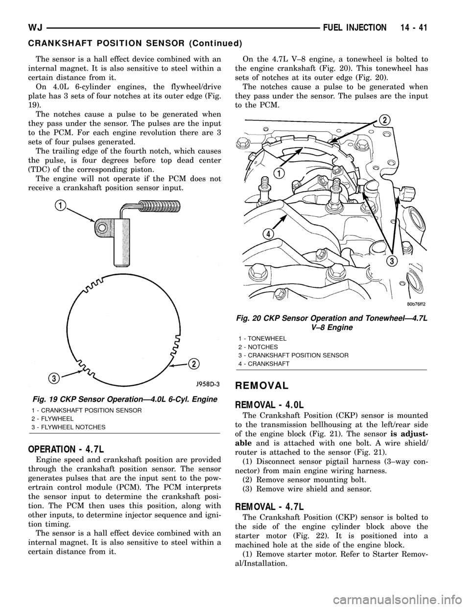
On 4.0L 6-cylinder engines, the flywheel/drive
plate has 3 sets of four notches at its outer edge (Fig.
19).
The notches cause a pulse to be generated when
they pass under the sensor. The pulses are the input
to the PCM. For each engine revolution there are 3
sets of four pulses generated.
The trailing edge of the fourth notch, which causes
the pulse, is four degrees before top dead center
(TDC) of the corresponding piston.
The engine will not operate if the PCM does not
receive a crankshaft position sensor input.
OPERATION - 4.7L
Engine speed and crankshaft position are provided
through the crankshaft position sensor. The sensor
generates pulses that are the input sent to the pow-
ertrain control module (PCM). The PCM interprets
the sensor input to determine the crankshaft posi-
tion. The PCM then uses this position, along with
other inputs, to determine injector sequence and igni-
tion timing.
The sensor is a hall effect device combined with an
internal magnet. It is also sensitive to steel within a
certain distance from it.On the 4.7L V±8 engine, a tonewheel is bolted to
the engine crankshaft (Fig. 20). This tonewheel has
sets of notches at its outer edge (Fig. 20).
The notches cause a pulse to be generated when
they pass under the sensor. The pulses are the input
to the PCM.
REMOVAL
REMOVAL - 4.0L
The Crankshaft Position (CKP) sensor is mounted
to the transmission bellhousing at the left/rear side
of the engine block (Fig. 21). The sensoris adjust-
ableand is attached with one bolt. A wire shield/
router is attached to the sensor (Fig. 21).
(1) Disconnect sensor pigtail harness (3±way con-
nector) from main engine wiring harness.
(2) Remove sensor mounting bolt.
(3) Remove wire shield and sensor.
REMOVAL - 4.7L
The Crankshaft Position (CKP) sensor is bolted to
the side of the engine cylinder block above the
starter motor (Fig. 22). It is positioned into a
machined hole at the side of the engine block.
(1) Remove starter motor. Refer to Starter Remov-
al/Installation.
Fig. 19 CKP Sensor OperationÐ4.0L 6-Cyl. Engine
1 - CRANKSHAFT POSITION SENSOR
2 - FLYWHEEL
3 - FLYWHEEL NOTCHES
Fig. 20 CKP Sensor Operation and TonewheelÐ4.7L
V±8 Engine
1 - TONEWHEEL
2 - NOTCHES
3 - CRANKSHAFT POSITION SENSOR
4 - CRANKSHAFT
WJFUEL INJECTION 14 - 41
CRANKSHAFT POSITION SENSOR (Continued)
Page 1478 of 2199
STEERING
TABLE OF CONTENTS
page page
STEERING
DESCRIPTION - POWER STEERING SYSTEM . . 1
OPERATION - POWER STEERING SYSTEM . . . 1
DIAGNOSIS AND TESTING
DIAGNOSIS AND TESTING - POWER
STEERING SYSTEM....................2
DIAGNOSIS AND TESTING - STEERING
FLOW AND PRESSURE.................4DIAGNOSIS AND TESTING - 4.7L -
HYDRAULIC..........................5
COLUMN...............................7
GEAR.................................16
LINKAGE..............................26
PUMP.................................31
STEERING
DESCRIPTION - POWER STEERING SYSTEM
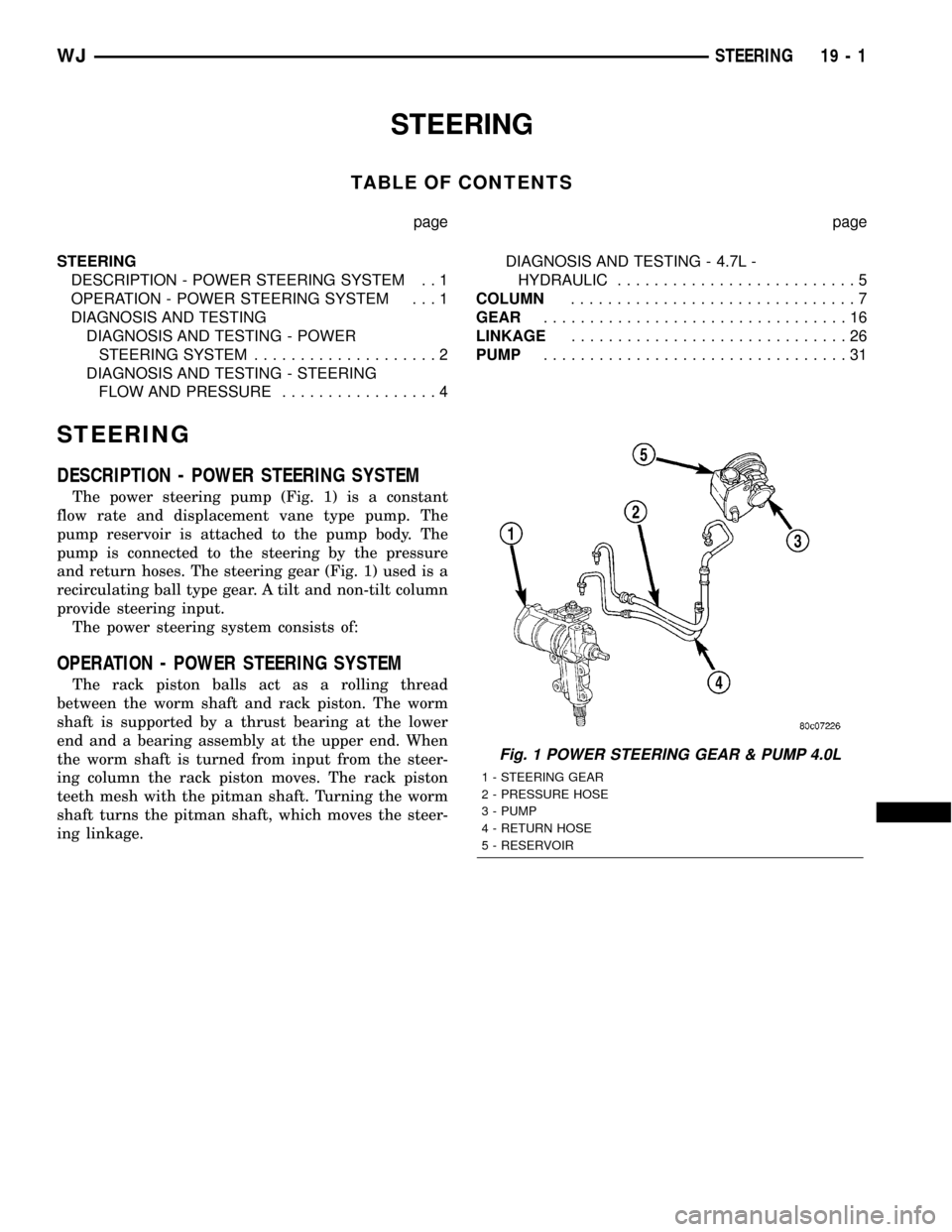
The power steering pump (Fig. 1) is a constant
flow rate and displacement vane type pump. The
pump reservoir is attached to the pump body. The
pump is connected to the steering by the pressure
and return hoses. The steering gear (Fig. 1) used is a
recirculating ball type gear. A tilt and non-tilt column
provide steering input.
The power steering system consists of:
OPERATION - POWER STEERING SYSTEM
The rack piston balls act as a rolling thread
between the worm shaft and rack piston. The worm
shaft is supported by a thrust bearing at the lower
end and a bearing assembly at the upper end. When
the worm shaft is turned from input from the steer-
ing column the rack piston moves. The rack piston
teeth mesh with the pitman shaft. Turning the worm
shaft turns the pitman shaft, which moves the steer-
ing linkage.
Fig. 1 POWER STEERING GEAR & PUMP 4.0L
1 - STEERING GEAR
2 - PRESSURE HOSE
3 - PUMP
4 - RETURN HOSE
5 - RESERVOIR
WJSTEERING 19 - 1
Page 1493 of 2199

GEAR
TABLE OF CONTENTS
page page
GEAR
DESCRIPTION.........................16
OPERATION...........................16
REMOVAL.............................16
INSTALLATION.........................16
ADJUSTMENTS
STEERING GEAR.....................18
SPECIFICATIONS
POWER STEERING GEAR..............18
SPECIAL TOOLS
POWER STEERING GEAR..............19
PITMAN SHAFT
REMOVAL.............................20INSTALLATION.........................20
PITMAN SHAFT BEARING
REMOVAL.............................22
INSTALLATION.........................22
PITMAN SHAFT SEAL
REMOVAL.............................22
INSTALLATION.........................23
RACK PISTON/VALVE ASSEMBLY
REMOVAL.............................23
INSTALLATION.........................25
STUB SHAFT HOUSING
REMOVAL.............................25
INSTALLATION.........................25
GEAR
DESCRIPTION
The power steering gear is a recirculating ball type
gear (Fig. 1) .
The following gear components can be serviced:
²Pitman Shaft and Cover
²Pitman Shaft Bearings
²Pitman Shaft Oil Seal/Dust Seal
²Stud Shaft Housing with Seal
²O-Rings and Teflon Rings
NOTE: If rack piston assembly is damaged the gear
must be replaced.
OPERATION
The gear acts as a rolling thread between the
worm shaft and rack piston. The worm shaft is sup-
ported by a thrust bearing at the lower end and a
bearing assembly at the upper end. When the worm
shaft is turned the rack piston moves. The rack pis-
ton teeth mesh with the pitman shaft. Turning the
worm shaft turns the pitman shaft, which turns the
steering linkage.
REMOVAL
(1) Place the front wheels in the straight ahead
position with the steering wheel centered and locked.
(2) Remove the air cleaner housing,(Refer to 9 -
ENGINE/AIR INTAKE SYSTEM/AIR CLEANER
HOUSING - REMOVAL).
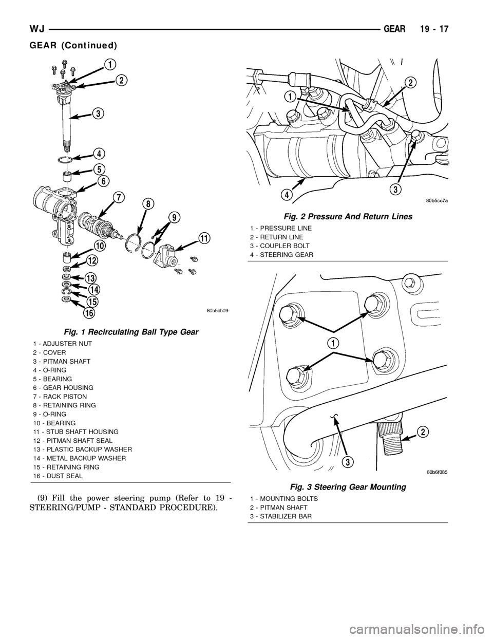
(3) Drain or siphon the power steering system.(4) Remove the pressure and return lines (Fig.
2)from the steering gear. Refer to hose removal in
this section.
(5) Remove the column coupler shaft bolt (Fig.
2)and remove the shaft from the gear.
(6) Raise and support the vehicle.
(7) Remove the left front wheel and tire assembly.
(8) Remove the pitman arm from gear with Puller
C-4150A.
(9) Remove the windshield washer reservoir,(Refer
to 8 - ELECTRICAL/WIPERS/WASHERS/WASHER
RESERVOIR - REMOVAL).
(10) Remove the steering gear mounting bolts.
Remove the steering gear out of the engine compart-
ment (Fig. 3).
INSTALLATION
(1) Position the steering gear on the frame rail and
install the bolts. Tighten the bolts to 108 N´m (80 ft.
lbs.) torque.
(2) Install the pitman arm and tighten nut to 251
N´m (185 ft. lbs.).
(3) Install windshield washer reservoir,(Refer to 8 -
ELECTRICAL/WIPERS/WASHERS/WASHER RES-
ERVOIR - INSTALLATION).
(4) Install the wheel and tire assembly.
(5) Remove the support and lower the vehicle.
(6) Install the pressure and return hoses to the
steering gear and tighten to 20-38 N´m (14-28 ft.
lbs.).
(7) Install the column coupler shaft.
(8) Install the air cleaner housing,(Refer to 9 -
ENGINE/AIR INTAKE SYSTEM/AIR CLEANER
HOUSING - INSTALLATION).
19 - 16 GEARWJ
Page 1494 of 2199
(9) Fill the power steering pump (Refer to 19 -
STEERING/PUMP - STANDARD PROCEDURE).
Fig. 1 Recirculating Ball Type Gear
1 - ADJUSTER NUT
2 - COVER
3 - PITMAN SHAFT
4 - O-RING
5 - BEARING
6 - GEAR HOUSING
7 - RACK PISTON
8 - RETAINING RING
9 - O-RING
10 - BEARING
11 - STUB SHAFT HOUSING
12 - PITMAN SHAFT SEAL
13 - PLASTIC BACKUP WASHER
14 - METAL BACKUP WASHER
15 - RETAINING RING
16 - DUST SEAL
Fig. 2 Pressure And Return Lines
1 - PRESSURE LINE
2 - RETURN LINE
3 - COUPLER BOLT
4 - STEERING GEAR
Fig. 3 Steering Gear Mounting
1 - MOUNTING BOLTS
2 - PITMAN SHAFT
3 - STABILIZER BAR
WJGEAR 19 - 17
GEAR (Continued)
Page 1500 of 2199
(9) Remove pitman shaft oil seal from the housing
with a Puller 7794-A and Slide Hammer C-637 (Fig.
7).
(10) Drop Driver 8277 through the top bearing and
align the driver up with the lower bearing. (Fig. 9).
Install Handle C-4171 into the driver and remove the
lower bearing.
(11) Turn the gear over and remover the upper
bearing with Driver 8277 and Handle C-4171.
INSTALLATION
(1) Install upper pitman shaft bearing, with Driver
8294 and Handle C-4171 (Fig. 10). Drive bearing into
housing until the driver bottoms out.
NOTE: Install upper pitman shaft bearing with the
part number/letters facing the driver.
(2) Install lower pitman shaft bearing with the
other side Driver 8294 and Handle C-4171 (Fig. 11).
Drive bearing into housing until the bearing shoulder
is seated against the housing.
(3) Coat the oil seal and backup washers withspe-
cial greasesupplied with the new seal.
(4) Install the oil seal with Driver 8294 and Han-
dle C-4171.
(5) Install plastic backup washer.
NOTE: The plastic backup washer has a lip on the
inside diameter that faces down towards the oil
seal.
(6) Install metal backup washer.
(7) Install the retainer ring with snap ring pliers.
(8) Coat the dust seal withspecial greasesup-
plied with the new seal.
(9) Install dust seal with Driver 8294 and Handle
C-4171.
(10) Install new pitman shaft cover o-ring.
(11) Install pitman shaft assembly into the hous-
ing.
(12) Install cover bolts and tighten to 62 N´m (46
ft. lbs.).
(13) Perform over-center rotation torque adjust-
ment.
RACK PISTON/VALVE
ASSEMBLY
REMOVAL
(1) Remove the steering gear (Refer to 19 -
STEERING/GEAR - REMOVAL).
(2) Clean exposed end of pitman shaft and housing
with a wire brush.
(3) Rotate the stub shaft with a wrench (Fig.
5)from stop to stop and count the number of turns.(4) Center the stub shaft by rotating it from the
stop 1/2 of the total amount of turns.
NOTE: The pitman shaft will not clear the housing if
it is not centered.
(5) Remove pitman shaft cover bolts and remove
the shaft assembly (Fig. 6).
(6) Remove the pitman shaft cover o-ring.
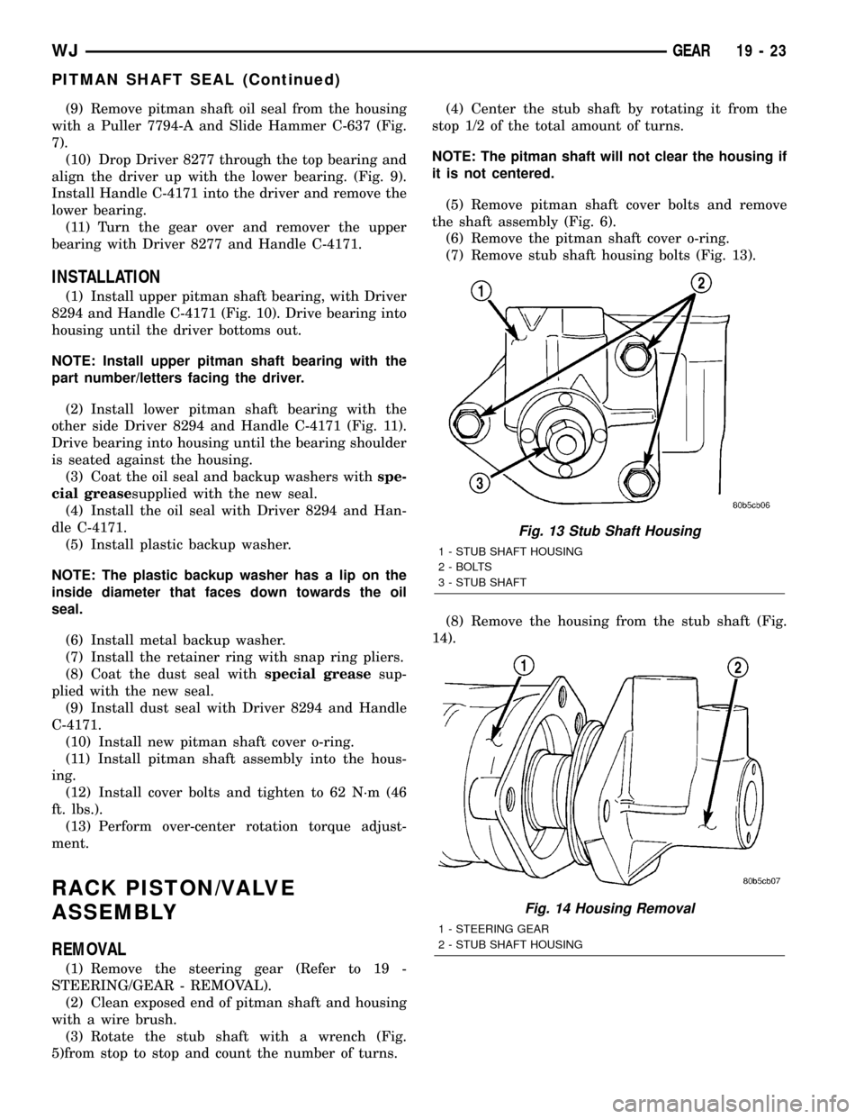
(7) Remove stub shaft housing bolts (Fig. 13).
(8) Remove the housing from the stub shaft (Fig.
14).
Fig. 13 Stub Shaft Housing
1 - STUB SHAFT HOUSING
2 - BOLTS
3 - STUB SHAFT
Fig. 14 Housing Removal
1 - STEERING GEAR
2 - STUB SHAFT HOUSING
WJGEAR 19 - 23
PITMAN SHAFT SEAL (Continued)
Page 1501 of 2199
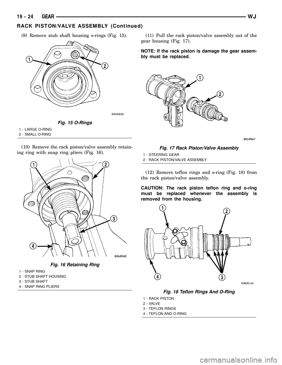
(9) Remove stub shaft housing o-rings (Fig. 15).
(10) Remove the rack piston/valve assembly retain-
ing ring with snap ring pliers (Fig. 16).(11) Pull the rack piston/valve assembly out of the
gear housing (Fig. 17).
NOTE: If the rack piston is damage the gear assem-
bly must be replaced.
(12) Remove teflon rings and o-ring (Fig. 18) from
the rack piston/valve assembly.
CAUTION: The rack piston teflon ring and o-ring
must be replaced whenever the assembly is
removed from the housing.
Fig. 15 O-Rings
1 - LARGE O-RING
2 - SMALL O-RING
Fig. 16 Retaining Ring
1 - SNAP RING
2 - STUB SHAFT HOUSING
3 - STUB SHAFT
4 - SNAP RING PLIERS
Fig. 17 Rack Piston/Valve Assembly
1 - STEERING GEAR
2 - RACK PISTON/VALVE ASSEMBLY
Fig. 18 Teflon Rings And O-Ring
1 - RACK PISTON
2 - VALVE
3 - TEFLON RINGS
4 - TEFLON AND O-RING
19 - 24 GEARWJ
RACK PISTON/VALVE ASSEMBLY (Continued)
Page 1502 of 2199
INSTALLATION
(1) Lubricate new o-ring and teflon rings with
power steering fluid and install on the rack piston/
valve assembly.
(2) Lubricate the rack piston/valve assembly with
power steering fluid.
(3) Slide the assembly into the gear housing.
(4) Install new stub shaft housing o-rings and
install the housing. Tighten the housing bolts to 62
N´m (46 ft. lbs.).
(5) Install new o-ring on the pitman shaft cover.
(6) Install the pitman shaft into the gear housing.
(7) Install the pitman shaft cover bolts and tighten
to 62 N´m (46 ft. lbs.).
(8) Perform over-center rotation torque adjustment
(Refer to 19 - STEERING/GEAR - ADJUSTMENTS)..
(9) Install the steering gear (Refer to 19 - STEER-
ING/GEAR - INSTALLATION).
(10) Fill the power steering pump (Refer to 19 -
STEERING/PUMP - STANDARD PROCEDURE).
STUB SHAFT HOUSING
REMOVAL
NOTE: If stub shaft housing, seal or bearing is dam-
aged the housing must be replaced.
(1) Remove the steering gear (Refer to 19 -
STEERING/GEAR - REMOVAL).
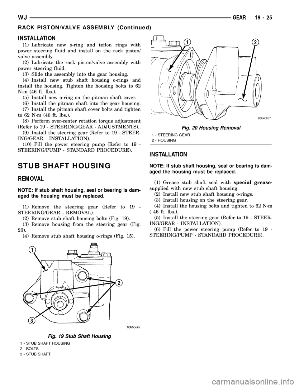
(2) Remove stub shaft housing bolts (Fig. 19).
(3) Remove housing from the steering gear (Fig.
20).
(4) Remove stub shaft housing o-rings (Fig. 15).
INSTALLATION
NOTE: If stub shaft housing, seal or bearing is dam-
aged the housing must be replaced.
(1) Grease stub shaft seal withspecial grease-
supplied with new stub shaft housing.
(2) Install new stub shaft housing o-rings.
(3) Install housing on the steering gear.
(4) Install the housing bolts and tighten to 62 N´m
( 46 ft. lbs.).
(5) Install the steering gear (Refer to 19 - STEER-
ING/GEAR - INSTALLATION).
(6) Fill the power steering pump (Refer to 19 -
STEERING/PUMP - STANDARD PROCEDURE).
Fig. 19 Stub Shaft Housing
1 - STUB SHAFT HOUSING
2 - BOLTS
3 - STUB SHAFT
Fig. 20 Housing Removal
1 - STEERING GEAR
2 - HOUSING
WJGEAR 19 - 25
RACK PISTON/VALVE ASSEMBLY (Continued)
Page 1521 of 2199

STANDARD PROCEDURE - FLUID AND
FILTER REPLACEMENT................71
STANDARD PROCEDURE - TRANSMISSION
FILL................................72
FRONT CLUTCH
DESCRIPTION.........................73
OPERATION...........................74
DISASSEMBLY.........................74
INSPECTION..........................74
ASSEMBLY............................74
FRONT SERVO
DESCRIPTION.........................77
OPERATION...........................77
DISASSEMBLY.........................77
CLEANING............................77
INSPECTION..........................77
ASSEMBLY............................77
GEARSHIFT CABLE
DIAGNOSIS AND TESTING - GEARSHIFT
CABLE..............................78
REMOVAL.............................78
INSTALLATION.........................79
ADJUSTMENTS - GEARSHIFT CABLE.......79
OIL PUMP
DESCRIPTION.........................80
OPERATION...........................80
STANDARD PROCEDURE - OIL PUMP
VOLUME CHECK......................81
DISASSEMBLY.........................81
CLEANING............................83
INSPECTION..........................83
ASSEMBLY............................83
OUTPUT SHAFT FRONT BEARING
REMOVAL.............................85
INSTALLATION.........................85
OUTPUT SHAFT REAR BEARING
REMOVAL.............................85
INSTALLATION.........................85
OVERDRIVE CLUTCH
DESCRIPTION.........................86
OPERATION...........................86
OVERDRIVE OFF SWITCH
DESCRIPTION.........................86
OPERATION...........................86
DIAGNOSIS AND TESTING - OVERDRIVE
ELECTRICAL CONTROLS...............87
OVERDRIVE UNIT
REMOVAL.............................87
DISASSEMBLY.........................88
CLEANING............................95
INSPECTION..........................95
ASSEMBLY............................95
INSTALLATION........................104
OVERRUNNING CLUTCH CAM/OVERDRIVE
PISTON RETAINER
DESCRIPTION........................105
OPERATION..........................105DISASSEMBLY........................106
CLEANING...........................106
INSPECTION.........................106
ASSEMBLY...........................106
PARK LOCK CABLE
REMOVAL............................108
INSTALLATION........................108
PARK/NEUTRAL POSITION SWITCH
DIAGNOSIS AND TESTING - PARK/NEUTRAL
POSITION SWITCH...................109
REMOVAL............................109
INSTALLATION........................109
PISTONS
DESCRIPTION........................110
OPERATION..........................110
PLANETARY GEARTRAIN/OUTPUT SHAFT
DESCRIPTION........................112
OPERATION..........................112
DISASSEMBLY........................112
INSPECTION..........................113
ASSEMBLY...........................113
REAR CLUTCH
DESCRIPTION........................118
OPERATION..........................118
DISASSEMBLY........................119
CLEANING...........................119
INSPECTION.........................120
ASSEMBLY...........................120
REAR SERVO
DESCRIPTION........................122
OPERATION..........................122
DISASSEMBLY........................122
CLEANING...........................122
ASSEMBLY...........................123
SHIFT MECHANISM
DESCRIPTION........................123
OPERATION..........................123
REMOVAL............................123
INSTALLATION........................125
SOLENOID
DESCRIPTION........................125
OPERATION..........................126
SPEED SENSOR
DESCRIPTION........................126
OPERATION..........................126
THROTTLE VALVE CABLE
DESCRIPTION........................126
ADJUSTMENTS - TRANSMISSION THROTTLE
VALVE CABLE.......................126
TORQUE CONVERTER
DESCRIPTION........................128
OPERATION..........................132
REMOVAL............................133
INSTALLATION........................133
TORQUE CONVERTER DRAINBACK VALVE
DESCRIPTION........................134
OPERATION..........................134
21 - 2 AUTOMATIC TRANSMISSION - 42REWJ