2003 JEEP GRAND CHEROKEE Power steering
[x] Cancel search: Power steeringPage 1231 of 2199
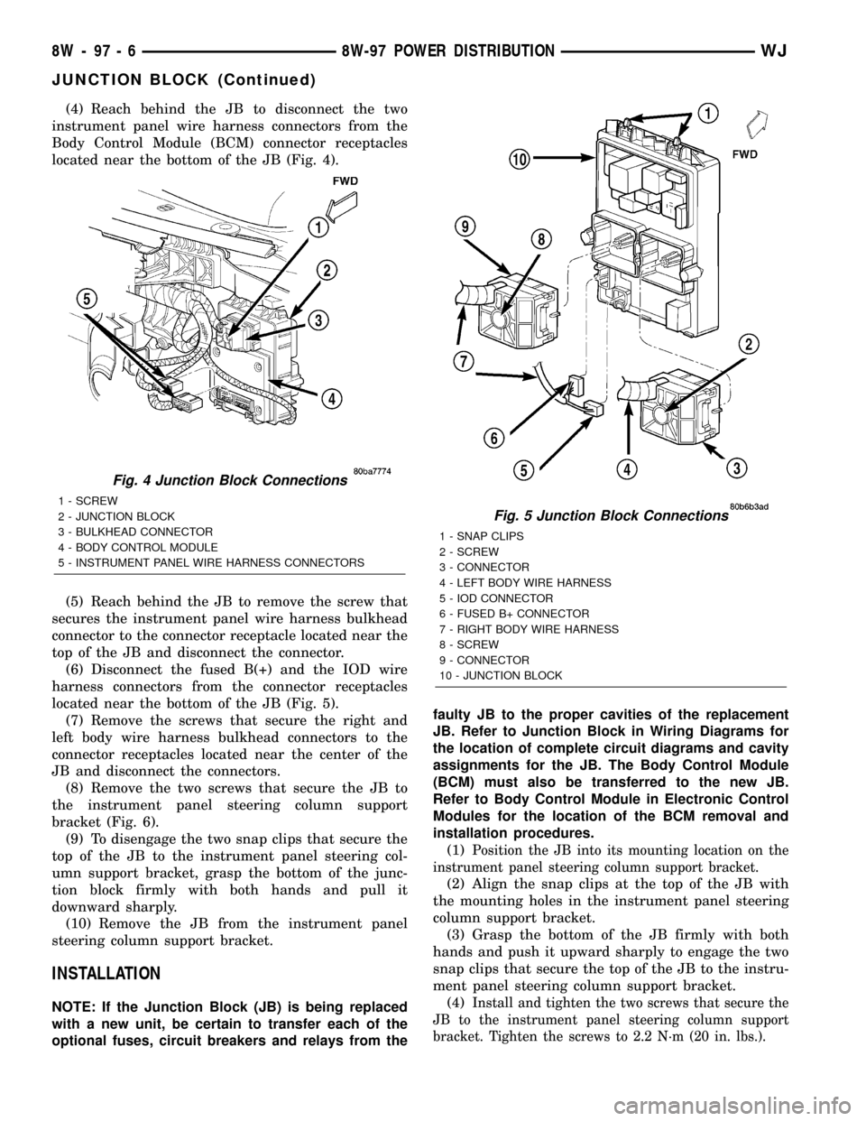
(4) Reach behind the JB to disconnect the two
instrument panel wire harness connectors from the
Body Control Module (BCM) connector receptacles
located near the bottom of the JB (Fig. 4).
(5) Reach behind the JB to remove the screw that
secures the instrument panel wire harness bulkhead
connector to the connector receptacle located near the
top of the JB and disconnect the connector.
(6) Disconnect the fused B(+) and the IOD wire
harness connectors from the connector receptacles
located near the bottom of the JB (Fig. 5).
(7) Remove the screws that secure the right and
left body wire harness bulkhead connectors to the
connector receptacles located near the center of the
JB and disconnect the connectors.
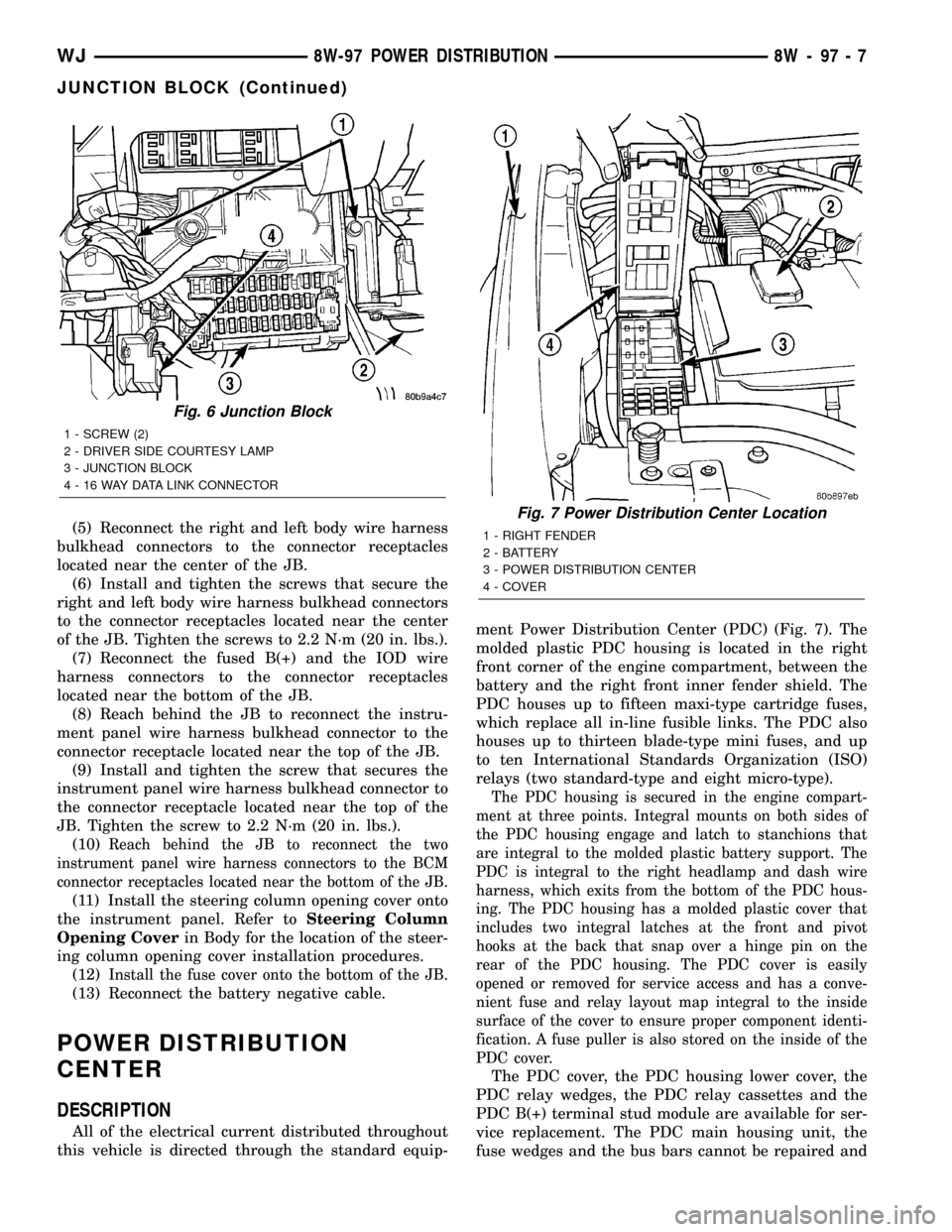
(8) Remove the two screws that secure the JB to
the instrument panel steering column support
bracket (Fig. 6).
(9) To disengage the two snap clips that secure the
top of the JB to the instrument panel steering col-
umn support bracket, grasp the bottom of the junc-
tion block firmly with both hands and pull it
downward sharply.
(10) Remove the JB from the instrument panel
steering column support bracket.
INSTALLATION
NOTE: If the Junction Block (JB) is being replaced
with a new unit, be certain to transfer each of the
optional fuses, circuit breakers and relays from thefaulty JB to the proper cavities of the replacement
JB. Refer to Junction Block in Wiring Diagrams for
the location of complete circuit diagrams and cavity
assignments for the JB. The Body Control Module
(BCM) must also be transferred to the new JB.
Refer to Body Control Module in Electronic Control
Modules for the location of the BCM removal and
installation procedures.
(1)
Position the JB into its mounting location on the
instrument panel steering column support bracket.
(2) Align the snap clips at the top of the JB with
the mounting holes in the instrument panel steering
column support bracket.
(3) Grasp the bottom of the JB firmly with both
hands and push it upward sharply to engage the two
snap clips that secure the top of the JB to the instru-
ment panel steering column support bracket.
(4)
Install and tighten the two screws that secure the
JB to the instrument panel steering column support
bracket. Tighten the screws to 2.2 N´m (20 in. lbs.).
Fig. 4 Junction Block Connections
1 - SCREW
2 - JUNCTION BLOCK
3 - BULKHEAD CONNECTOR
4 - BODY CONTROL MODULE
5 - INSTRUMENT PANEL WIRE HARNESS CONNECTORS
Fig. 5 Junction Block Connections
1 - SNAP CLIPS
2 - SCREW
3 - CONNECTOR
4 - LEFT BODY WIRE HARNESS
5 - IOD CONNECTOR
6 - FUSED B+ CONNECTOR
7 - RIGHT BODY WIRE HARNESS
8 - SCREW
9 - CONNECTOR
10 - JUNCTION BLOCK
8W - 97 - 6 8W-97 POWER DISTRIBUTIONWJ
JUNCTION BLOCK (Continued)
Page 1232 of 2199
(5) Reconnect the right and left body wire harness
bulkhead connectors to the connector receptacles
located near the center of the JB.
(6) Install and tighten the screws that secure the
right and left body wire harness bulkhead connectors
to the connector receptacles located near the center
of the JB. Tighten the screws to 2.2 N´m (20 in. lbs.).
(7) Reconnect the fused B(+) and the IOD wire
harness connectors to the connector receptacles
located near the bottom of the JB.
(8) Reach behind the JB to reconnect the instru-
ment panel wire harness bulkhead connector to the
connector receptacle located near the top of the JB.
(9) Install and tighten the screw that secures the
instrument panel wire harness bulkhead connector to
the connector receptacle located near the top of the
JB. Tighten the screw to 2.2 N´m (20 in. lbs.).
(10)
Reach behind the JB to reconnect the two
instrument panel wire harness connectors to the BCM
connector receptacles located near the bottom of the JB.
(11) Install the steering column opening cover onto
the instrument panel. Refer toSteering Column
Opening Coverin Body for the location of the steer-
ing column opening cover installation procedures.
(12)
Install the fuse cover onto the bottom of the JB.
(13) Reconnect the battery negative cable.
POWER DISTRIBUTION
CENTER
DESCRIPTION
All of the electrical current distributed throughout
this vehicle is directed through the standard equip-ment Power Distribution Center (PDC) (Fig. 7). The
molded plastic PDC housing is located in the right
front corner of the engine compartment, between the
battery and the right front inner fender shield. The
PDC houses up to fifteen maxi-type cartridge fuses,
which replace all in-line fusible links. The PDC also
houses up to thirteen blade-type mini fuses, and up
to ten International Standards Organization (ISO)
relays (two standard-type and eight micro-type).
The PDC housing is secured in the engine compart-
ment at three points. Integral mounts on both sides of
the PDC housing engage and latch to stanchions that
are integral to the molded plastic battery support. The
PDC is integral to the right headlamp and dash wire
harness, which exits from the bottom of the PDC hous-
ing. The PDC housing has a molded plastic cover that
includes two integral latches at the front and pivot
hooks at the back that snap over a hinge pin on the
rear of the PDC housing. The PDC cover is easily
opened or removed for service access and has a conve-
nient fuse and relay layout map integral to the inside
surface of the cover to ensure proper component identi-
fication. A fuse puller is also stored on the inside of the
PDC cover.
The PDC cover, the PDC housing lower cover, the
PDC relay wedges, the PDC relay cassettes and the
PDC B(+) terminal stud module are available for ser-
vice replacement. The PDC main housing unit, the
fuse wedges and the bus bars cannot be repaired and
Fig. 6 Junction Block
1 - SCREW (2)
2 - DRIVER SIDE COURTESY LAMP
3 - JUNCTION BLOCK
4 - 16 WAY DATA LINK CONNECTOR
Fig. 7 Power Distribution Center Location
1 - RIGHT FENDER
2 - BATTERY
3 - POWER DISTRIBUTION CENTER
4 - COVER
WJ8W-97 POWER DISTRIBUTION 8W - 97 - 7
JUNCTION BLOCK (Continued)
Page 1237 of 2199
PDC LOWER COVER INSTALLATION
(1) Align the PDC housing lower cover on the bot-
tom of the PDC.
(2) Evenly press the lower cover into place until
latches are fully engaged.
(3) Where the right headlamp and dash harness
enters the PDC, tape the harness securely to the
trough formation on the PDC lower cover.
(4) Install the PDC in its mounting location on the
battery support.
(5) Install the battery wire harness over the two
PDC B+ terminal studs. Torque the nuts to 11.3 N´m
(100 in. lbs.).
(6) Install the battery. Refer to Battery System for
the procedure.
(7) Install the PDC cover.
INSTALLATION
The Power Distribution Center (PDC) main hous-
ing unit, the PDC fuse wedges and the PDC bus bars
cannot be repaired and are only serviced as a unit
with the right headlamp and dash wire harness. If
the PDC main housing unit, the fuse wedges or the
bus bars are faulty or damaged, the entire PDC and
right headlamp and dash wire harness unit must be
replaced.
(1) Position the PDC and the right headlamp and
dash wire harness unit in the engine compartment.
(2) Engage the PDC housing mounts with the
stanchions of the battery support and push the unit
downward until the mount latches fully engage the
mounting tabs on the stanchions.
(3) Install the two-holed eyelet of the battery wire
harness PDC take outs onto the two PDC B(+) termi-
nal studs.
(4) Install and tighten the nuts that secure the
eyelet of the battery wire harness PDC take outs to
the B(+) terminal studs. Tighten the nuts to 11.3
N´m (100 in. lbs.).
(5) Engage each of the retainers that secure the
right headlamp and dash wire harness to the vehicle
body and chassis components. Refer toConnector
Locationsin Wiring Diagrams for the location of
more information on the right headlamp and dash
wire harness retainer locations.
(6) Install all of the fasteners that secure each of
the right headlamp and dash wire harness ground
eyelets to the vehicle body and chassis components.
Refer toConnector Locationsin Wiring Diagrams
for the location of more information on the ground
eyelet locations.
(7) Reconnect each of the right headlamp and dash
wire harness connectors. Refer toConnector Loca-
tionsin Wiring Diagrams for the location of more
information on the right headlamp and dash wire
harness connector locations. For connectors securedwith screws, tighten the screws to 4.3 N´m (38 in.
lbs.).
(8) Reconnect the battery negative cable.
POWER OUTLET
DESCRIPTION - FRONT POWER OUTLET
An accessory power outlet is standard equipment
on this model. The power outlet is installed in the
instrument panel center lower bezel, which is located
near the bottom of the instrument panel center stack
area, below the heater and air conditioner controls.
The power outlet base is secured by a snap fit within
the center lower bezel. A hinged door with an over-
center spring flips closed to conceal and protect the
power outlet base when the power outlet is not being
used, and flips open below the center lower bezel
while the power outlet is in use.
The power outlet receptacle unit and the power
outlet door are each available for service replace-
ment.
OPERATION - FRONT POWER OUTLET
The power outlet base or receptacle shell is con-
nected to ground, and an insulated contact in the
bottom of the shell is connected to battery current.
The power outlet receives battery voltage from a fuse
in the junction block at all times.
While the power outlet is very similar to a cigar
lighter base unit, it does not include the two small
spring-clip retainers inside the bottom of the recepta-
cle shell that are used to secure the cigar lighter
heating element to the insulated contact.
DIAGNOSIS AND TESTING - POWER OUTLET
For complete circuit diagrams, refer toHorn/Ci-
gar Lighter/Power Outletin Wiring Diagrams.
WARNING: REFER TO RESTRAINTS BEFORE
ATTEMPTING ANY STEERING WHEEL, STEERING
COLUMN, OR INSTRUMENT PANEL COMPONENT
DIAGNOSIS OR SERVICE. FAILURE TO TAKE THE
PROPER PRECAUTIONS COULD RESULT IN ACCI-
DENTAL AIRBAG DEPLOYMENT AND POSSIBLE
PERSONAL INJURY.
(1) Check the fused B(+) fuse in the junction block.
If OK, go to Step 2. If not OK, repair the shorted cir-
cuit or component as required and replace the faulty
fuse.
(2) Check for battery voltage at the fused B(+) fuse
in the junction block. If OK, go to Step 3. If not OK,
repair the open fused B(+) circuit to the Power Dis-
tribution Center (PDC) fuse as required.
(3) Open the power outlet door. Check for continu-
ity between the inside circumference of the power
8W - 97 - 12 8W-97 POWER DISTRIBUTIONWJ
POWER DISTRIBUTION CENTER (Continued)
Page 1239 of 2199
The cigar lighter relay cannot be repaired or
adjusted and, if faulty or damaged, it must be
replaced.
OPERATION
The ISO relay consists of an electromagnetic coil, a
resistor or diode, and three (two fixed and one mov-
able) electrical contacts. The movable (common feed)
relay contact is held against one of the fixed contacts
(normally closed) by spring pressure. When the elec-
tromagnetic coil is energized, it draws the movable
contact away from the normally closed fixed contact,
and holds it against the other (normally open) fixed
contact.
When the electromagnetic coil is de-energized,
spring pressure returns the movable contact to the
normally closed position. The resistor or diode is con-
nected in parallel with the electromagnetic coil in the
relay, and helps to dissipate voltage spikes that are
produced when the coil is de-energized.
DIAGNOSIS AND TESTING - POWER OUTLET
RELAY
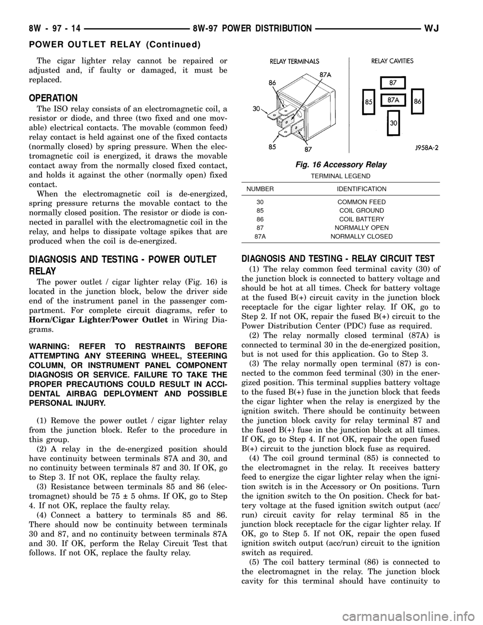
The power outlet / cigar lighter relay (Fig. 16) is
located in the junction block, below the driver side
end of the instrument panel in the passenger com-
partment. For complete circuit diagrams, refer to
Horn/Cigar Lighter/Power Outletin Wiring Dia-
grams.
WARNING: REFER TO RESTRAINTS BEFORE
ATTEMPTING ANY STEERING WHEEL, STEERING
COLUMN, OR INSTRUMENT PANEL COMPONENT
DIAGNOSIS OR SERVICE. FAILURE TO TAKE THE
PROPER PRECAUTIONS COULD RESULT IN ACCI-
DENTAL AIRBAG DEPLOYMENT AND POSSIBLE
PERSONAL INJURY.
(1) Remove the power outlet / cigar lighter relay
from the junction block. Refer to the procedure in
this group.
(2) A relay in the de-energized position should
have continuity between terminals 87A and 30, and
no continuity between terminals 87 and 30. If OK, go
to Step 3. If not OK, replace the faulty relay.
(3) Resistance between terminals 85 and 86 (elec-
tromagnet) should be 75 5 ohms. If OK, go to Step
4. If not OK, replace the faulty relay.
(4) Connect a battery to terminals 85 and 86.
There should now be continuity between terminals
30 and 87, and no continuity between terminals 87A
and 30. If OK, perform the Relay Circuit Test that
follows. If not OK, replace the faulty relay.
DIAGNOSIS AND TESTING - RELAY CIRCUIT TEST
(1) The relay common feed terminal cavity (30) of
the junction block is connected to battery voltage and
should be hot at all times. Check for battery voltage
at the fused B(+) circuit cavity in the junction block
receptacle for the cigar lighter relay. If OK, go to
Step 2. If not OK, repair the fused B(+) circuit to the
Power Distribution Center (PDC) fuse as required.
(2) The relay normally closed terminal (87A) is
connected to terminal 30 in the de-energized position,
but is not used for this application. Go to Step 3.
(3) The relay normally open terminal (87) is con-
nected to the common feed terminal (30) in the ener-
gized position. This terminal supplies battery voltage
to the fused B(+) fuse in the junction block that feeds
the cigar lighter when the relay is energized by the
ignition switch. There should be continuity between
the junction block cavity for relay terminal 87 and
the fused B(+) fuse in the junction block at all times.
If OK, go to Step 4. If not OK, repair the open fused
B(+) circuit to the junction block fuse as required.
(4) The coil ground terminal (85) is connected to
the electromagnet in the relay. It receives battery
feed to energize the cigar lighter relay when the igni-
tion switch is in the Accessory or On positions. Turn
the ignition switch to the On position. Check for bat-
tery voltage at the fused ignition switch output (acc/
run) circuit cavity for relay terminal 85 in the
junction block receptacle for the cigar lighter relay. If
OK, go to Step 5. If not OK, repair the open fused
ignition switch output (acc/run) circuit to the ignition
switch as required.
(5) The coil battery terminal (86) is connected to
the electromagnet in the relay. The junction block
cavity for this terminal should have continuity to
Fig. 16 Accessory Relay
TERMINAL LEGEND
NUMBER IDENTIFICATION
30 COMMON FEED
85 COIL GROUND
86 COIL BATTERY
87 NORMALLY OPEN
87A NORMALLY CLOSED
8W - 97 - 14 8W-97 POWER DISTRIBUTIONWJ
POWER OUTLET RELAY (Continued)
Page 1240 of 2199
ground at all times. If not OK, repair the open
ground circuit to ground as required.
REMOVAL
(1) Disconnect and isolate the battery negative
cable.
(2) Remove the steering column opening cover
from the instrument panel. Refer toSteering Col-
umn Opening Coverin Body for the procedure.
(3) The power outlet / cigar lighter relay is located
on the left side of the combination flasher in the
junction block.
(4) Remove the power outlet / cigar lighter relay
from the junction block.
INSTALLATION
(1) Position the power outlet / cigar lighter relay in
the proper receptacle in the junction block.
(2) Align the power outlet / cigar lighter relay ter-
minals with the terminal cavities in the junction
block receptacle.
(3) Push in firmly on the power outlet / cigar
lighter relay until the terminals are fully seated in
the terminal cavities in the junction block receptacle.
(4) Install the steering column opening cover onto
the instrument panel. Refer toSteering Column
Opening Coverin Body for the procedure.
(5) Reconnect the battery negative cable.
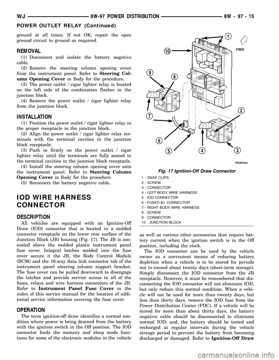
IOD WIRE HARNESS
CONNECTOR
DESCRIPTION
All vehicles are equipped with an Ignition-Off
Draw (IOD) connector that is located in a molded
connector receptacle on the lower rear surface of the
Junction Block (JB) housing (Fig. 17). The JB is con-
cealed above the molded plastic instrument panel
fuse cover. Integral latches molded into the fuse
cover secure it the JB, the Body Control Module
(BCM) and the 16-way data link connector tab of the
instrument panel steering column support bracket.
The fuse cover can be pulled downward to disengage
the latches and provide service access to all of the
fuses, relays and wire harness connectors of the JB.
Refer toInstrument Panel Fuse Coverin the
index of this service manual for the location of addi-
tional service information covering the fuse cover.
OPERATION
The term ignition-off draw identifies a normal con-
dition where power is being drained from the battery
with the ignition switch in the Off position. The IOD
connector feeds the memory and sleep mode func-
tions for some of the electronic modules in the vehicleas well as various other accessories that require bat-
tery current when the ignition switch is in the Off
position, including the clock.
The IOD connector can be used by the vehicle
owner as a convenient means of reducing battery
depletion when a vehicle is to be stored for periods
not to exceed about twenty days (short-term storage).
Simply disconnect the IOD connector from the JB
receptacle. However, it must be remembered that dis-
connecting the IOD connector will not eliminate IOD,
but only reduce this normal condition. When a vehi-
cle will not be used for more than twenty days, but
less than thirty days, remove the IOD fuse from the
Power Distribution Center (PDC). If a vehicle will be
stored for more than about thirty days, the battery
negative cable should be disconnected to eliminate
normal IOD; and, the battery should be tested and
recharged at regular intervals during the vehicle
storage period to prevent the battery from becoming
discharged or damaged. Refer toIgnition-Off Draw
Fig. 17 Ignition-Off Draw Connector
1 - SNAP CLIPS
2 - SCREW
3 - CONNECTOR
4 - LEFT BODY WIRE HARNESS
5 - IOD CONNECTOR
6 - FUSED B+ CONNECTOR
7 - RIGHT BODY WIRE HARNESS
8 - SCREW
9 - CONNECTOR
10 - JUNCTION BLOCK
WJ8W-97 POWER DISTRIBUTION 8W - 97 - 15
POWER OUTLET RELAY (Continued)
Page 1241 of 2199
FuseandBatteryin the index in this service man-
ual for the location of additional service information
covering the ignition-off draw fuse and the battery.
FUSE COVER
REMOVAL
(1) Disconnect and isolate the battery negative
cable.
(2) Pull down on the rear edge (nearest the rear of
the vehicle) of the instrument panel fuse cover until
the rear latches unsnap from the tabs on the lower
junction block housing and the side latch unsnaps
from the tab on the instrument panel steering col-
umn support bracket outboard of the 16-way data
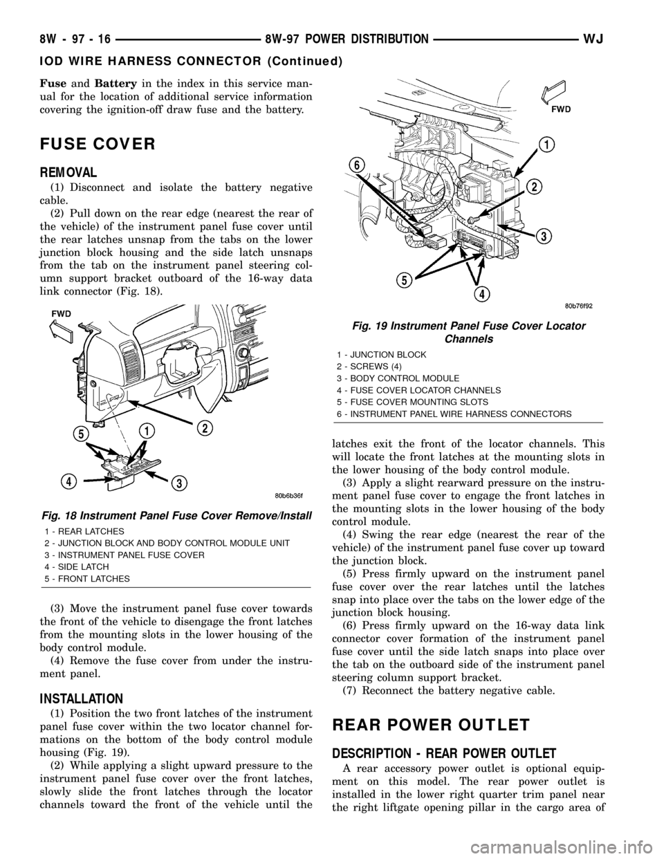
link connector (Fig. 18).
(3) Move the instrument panel fuse cover towards
the front of the vehicle to disengage the front latches
from the mounting slots in the lower housing of the
body control module.
(4) Remove the fuse cover from under the instru-
ment panel.
INSTALLATION
(1) Position the two front latches of the instrument
panel fuse cover within the two locator channel for-
mations on the bottom of the body control module
housing (Fig. 19).
(2) While applying a slight upward pressure to the
instrument panel fuse cover over the front latches,
slowly slide the front latches through the locator
channels toward the front of the vehicle until thelatches exit the front of the locator channels. This
will locate the front latches at the mounting slots in
the lower housing of the body control module.
(3) Apply a slight rearward pressure on the instru-
ment panel fuse cover to engage the front latches in
the mounting slots in the lower housing of the body
control module.
(4) Swing the rear edge (nearest the rear of the
vehicle) of the instrument panel fuse cover up toward
the junction block.
(5) Press firmly upward on the instrument panel
fuse cover over the rear latches until the latches
snap into place over the tabs on the lower edge of the
junction block housing.
(6) Press firmly upward on the 16-way data link
connector cover formation of the instrument panel
fuse cover until the side latch snaps into place over
the tab on the outboard side of the instrument panel
steering column support bracket.
(7) Reconnect the battery negative cable.
REAR POWER OUTLET
DESCRIPTION - REAR POWER OUTLET
A rear accessory power outlet is optional equip-
ment on this model. The rear power outlet is
installed in the lower right quarter trim panel near
the right liftgate opening pillar in the cargo area of
Fig. 18 Instrument Panel Fuse Cover Remove/Install
1 - REAR LATCHES
2 - JUNCTION BLOCK AND BODY CONTROL MODULE UNIT
3 - INSTRUMENT PANEL FUSE COVER
4 - SIDE LATCH
5 - FRONT LATCHES
Fig. 19 Instrument Panel Fuse Cover Locator
Channels
1 - JUNCTION BLOCK
2 - SCREWS (4)
3 - BODY CONTROL MODULE
4 - FUSE COVER LOCATOR CHANNELS
5 - FUSE COVER MOUNTING SLOTS
6 - INSTRUMENT PANEL WIRE HARNESS CONNECTORS
8W - 97 - 16 8W-97 POWER DISTRIBUTIONWJ
IOD WIRE HARNESS CONNECTOR (Continued)
Page 1255 of 2199

(7) Remove the fan assembly from the water pump
(Refer to 7 - COOLING/ENGINE/RADIATOR FAN -
REMOVAL).
(8) Remove the fan shroud.
(9) Disconnect the transmission fluid cooler lines
(automatic transmission).
(10) Discharge the A/C system (Refer to 24 -
HEATING & AIR CONDITIONING/PLUMBING -
STANDARD PROCEDURE).
(11) Remove the service valves and cap the com-
pressor ports.
(12) Remove the radiator or radiator/condenser (if
equipped with A/C).
(13) Disconnect the heater hoses at the engine
thermostat housing and water pump.
(14) Disconnect the accelerator cable, transmission
line pressure cable and speed control cable (if
equipped) from the throttle body.
(15) Remove cables from the bracket and secure
out of the way.
(16) Disconnect the body ground at the engine.
(17) Disconnect the following connectors and
secure their harness out of the way.
²Power steering pressure switch
²Coolant temperature sensor
²Six (6) fuel injector connectors
²Intake air temperature sensor
²Throttle position sensor
²Map sensor
²Crankshaft position sensor
²Oxygen sensor
²Camshaft position sensor
²Generator connector and B+ terminal wire
(18) Disconnect the coil rail electrical connections
and the oil pressure switch connector.
(19) Perform the fuel pressure release procedure
(Refer to 14 - FUEL SYSTEM/FUEL DELIVERY -
STANDARD PROCEDURE).
(20) Disconnect the fuel supply line at the injector
rail (Refer to 14 - FUEL SYSTEM/FUEL DELIVERY/
QUICK CONNECT FITTING - STANDARD PROCE-
DURE).
(21) Remove the fuel line bracket from the intake
manifold.
(22) Remove the air cleaner assembly (Fig. 5).
(23) Disconnect the hoses from the fittings at the
steering gear.
(24) Drain the pump reservoir.
(25) Cap the fittings on the hoses and steering
gear to prevent foreign objects from entering the sys-
tem.
(26) Raise and support the vehicle.
(27) Disconnect the wires from the engine starter
motor solenoid.(28) Remove the engine starter motor (Refer to 8 -
ELECTRICAL/STARTING/STARTER MOTOR -
REMOVAL).
(29) Disconnect the oxygen sensor from the
exhaust pipe.
(30) Disconnect the exhaust pipe from the mani-
fold.
(31) Remove the exhaust pipe support.
(32) Remove the bending brace (Refer to 9 -
ENGINE/ENGINE BLOCK/STRUCT SUPPORT -
REMOVAL).
(33) Remove the engine flywheel/converter housing
access cover.
(34) Mark the converter and drive plate location.
(35) Remove the converter-to-drive plate bolts.
(36) Remove the upper engine flywheel/converter
housing bolts and loosen the bottom bolts.
(37) Remove the engine mount cushion-to-engine
compartment bracket bolts.
(38) Lower the vehicle.
(39) Attach a lifting device to the engine.
(40) Raise the engine off the front supports.
(41) Place a support or floor jack under the con-
verter (or engine flywheel) housing.
(42) Remove the remaining converter (or engine
flywheel) housing bolts.
(43) Lift the engine out of the engine compart-
ment.
Fig. 5 Air Cleaner Assembly
1 - POWER STEERING PUMP
2 - AIR CLEANER ASSEMBLY
9 - 12 ENGINE - 4.0LWJ
ENGINE - 4.0L (Continued)
Page 1256 of 2199

INSTALLATION
CAUTION: When installing the engine into a vehicle
equipped with an automatic transmission, be care-
ful not to damage the trigger wheel on the engine
flywheel.
(1) Attach a lifting device to the engine and lower
the engine into the engine compartment. For easier
installation, it may be necessary to remove the
engine mount bracket as an aid in alignment of the
engine to the transmission.
(2) Align the transmission torque converter hous-
ing with the engine.
(3) Loosely install the converter housing lower
bolts and install the next higher bolt and nut on each
side.
(4) Tighten all 4 bolts finger tight.
(5) Install the engine mount brackets (if removed).
(6) Lower the engine and engine mount brackets
onto the engine compartment cushions. Install the
bolts and finger tighten the nuts.
(7) Remove the engine lifting device.
(8) Raise and support the vehicle.
(9) Install the remaining engine flywheel/converter
housing bolts. Tighten all bolts to 38 N´m (28 ft. lbs.)
torque.
(10) Install the converter-to-drive plate bolts.
(11) Ensure the installation reference marks are
aligned.
(12) Install the engine flywheel/converter housing
access cover.
(13) Install the exhaust pipe support and tighten
the screw.
(14) Install the engine bending brace (Refer to 9 -
ENGINE/ENGINE BLOCK/STRUCT SUPPORT -
INSTALLATION).
(15) Tighten the engine mount-to-bracket bolts.
(16) Connect the vehicle speed sensor wire connec-
tions and tighten the screws.
(17) Connect the exhaust pipe to the manifold.
(18) Install the engine starter motor (Refer to 8 -
ELECTRICAL/STARTING/STARTER MOTOR -
INSTALLATION).
(19) Connect the wires to the engine starter motor
solenoid.
(20) Lower the vehicle.
(21) Connect all the vacuum hoses and wire con-
nectors identified during engine removal.
(22) Remove protective caps from the power steer-
ing hoses.
(23) Connect the hoses to the fittings at the steer-
ing gear. Tighten the nut to 52 N´m (38 ft. lbs.)
torque.
(24) Fill the pump reservoir with fluid.(25) Inspect the fuel supply line o-ring(s) and
replace if necessary. Connect fuel supply line to injec-
tior rail and verify connection by pulling outward on
the line.
(26) Install the fuel line bracket to the intake
manifold.
(27) Connect the coil rail electrical connectors and
oil pressure switch connector.
(28) Connect the following electrical connectors:
²Power steering pressure switch
²Coolant temperature sensor
²Six (6) fuel injector connectors
²Intake air temperature sensor
²Throttle position sensor
²Map sensor
²Crankshaft position sensor
²Oxygen sensor
²Camshaft position sensor
²Generator connector and B+ terminal wire
(29) Connect all previously removed vacuum hoses.
(30) Connect the body ground strap.
(31) Install the throttle, transmission line pres-
sure, and speed control cables to their mounting
bracket and connect them to the throttle body.
(32) Connect the heater hoses at the engine ther-
mostat housing and water pump.
(33) Install the fan assembly (Refer to 7 - COOL-
ING/ENGINE/RADIATOR FAN - INSTALLATION).
(34) Place the fan shroud in position over the fan.
(35) Install the radiator (Refer to 7 - COOLING/
ENGINE/RADIATOR - INSTALLATION).
(36) Connect the service valves to the A/C com-
pressor ports, if equipped with A/C.
(37) Charge the air conditioner system (Refer to 24
- HEATING & AIR CONDITIONING/PLUMBING -
STANDARD PROCEDURE).
(38) Connect the radiator hoses and automatic
transmission fluid cooler pipes, if equipped.
(39) Install the fan shroud to the radiator or radi-
ator/condenser (if equipped with A/C).
(40) Install upper radiator support.
(41) Connect the upper radiator hose and tighten
the clamp.
(42) Connect the lower radiator hose and tighten
the clamp.
(43) Fill crankcase with engine oil. (Refer to
LUBRICATION & MAINTENANCE/FLUID CAPACI-
TIES - SPECIFICATIONS) for correct capacities.
(44) Fill the cooling system with reusable coolant
or new coolant (Refer to 7 - COOLING - STANDARD
PROCEDURE).
(45) Align the hood to the scribe marks. Install the
hood.
(46) Install the air cleaner assembly.
(47) Install the battery and connect the battery
cable.
WJENGINE - 4.0L 9 - 13
ENGINE - 4.0L (Continued)