2003 JEEP GRAND CHEROKEE Flush
[x] Cancel search: FlushPage 1843 of 2199
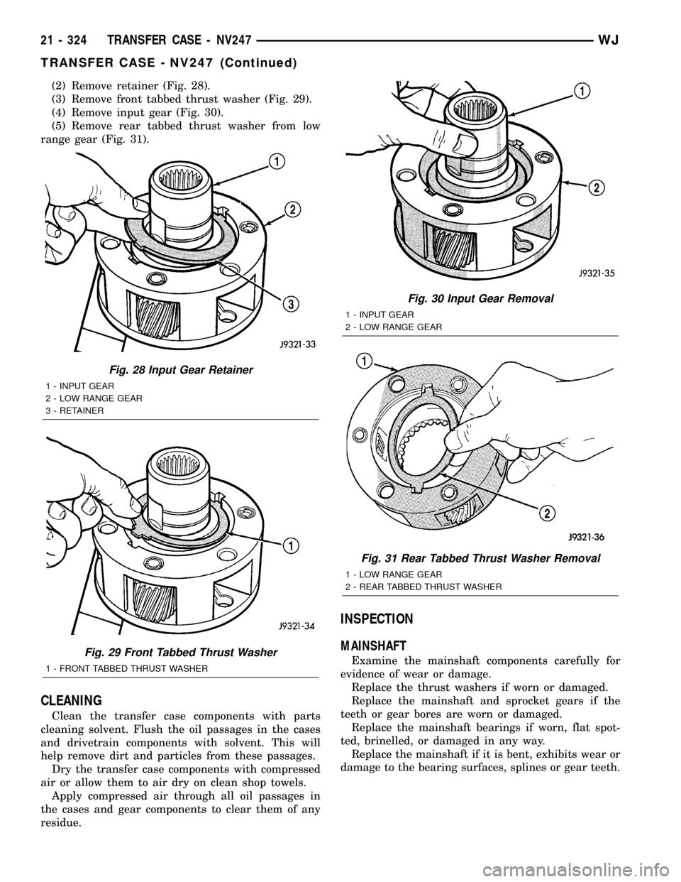
(2) Remove retainer (Fig. 28).
(3) Remove front tabbed thrust washer (Fig. 29).
(4) Remove input gear (Fig. 30).
(5) Remove rear tabbed thrust washer from low
range gear (Fig. 31).
CLEANING
Clean the transfer case components with parts
cleaning solvent. Flush the oil passages in the cases
and drivetrain components with solvent. This will
help remove dirt and particles from these passages.
Dry the transfer case components with compressed
air or allow them to air dry on clean shop towels.
Apply compressed air through all oil passages in
the cases and gear components to clear them of any
residue.
INSPECTION
MAINSHAFT
Examine the mainshaft components carefully for
evidence of wear or damage.
Replace the thrust washers if worn or damaged.
Replace the mainshaft and sprocket gears if the
teeth or gear bores are worn or damaged.
Replace the mainshaft bearings if worn, flat spot-
ted, brinelled, or damaged in any way.
Replace the mainshaft if it is bent, exhibits wear or
damage to the bearing surfaces, splines or gear teeth.
Fig. 28 Input Gear Retainer
1 - INPUT GEAR
2 - LOW RANGE GEAR
3 - RETAINER
Fig. 29 Front Tabbed Thrust Washer
1 - FRONT TABBED THRUST WASHER
Fig. 30 Input Gear Removal
1 - INPUT GEAR
2 - LOW RANGE GEAR
Fig. 31 Rear Tabbed Thrust Washer Removal
1 - LOW RANGE GEAR
2 - REAR TABBED THRUST WASHER
21 - 324 TRANSFER CASE - NV247WJ
TRANSFER CASE - NV247 (Continued)
Page 1846 of 2199
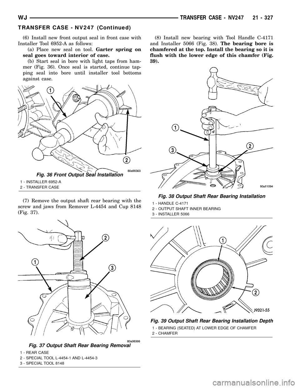
(6) Install new front output seal in front case with
Installer Tool 6952-A as follows:
(a) Place new seal on tool.Garter spring on
seal goes toward interior of case.
(b) Start seal in bore with light taps from ham-
mer (Fig. 36). Once seal is started, continue tap-
ping seal into bore until installer tool bottoms
against case.
(7) Remove the output shaft rear bearing with the
screw and jaws from Remover L-4454 and Cup 8148
(Fig. 37).(8) Install new bearing with Tool Handle C-4171
and Installer 5066 (Fig. 38).The bearing bore is
chamfered at the top. Install the bearing so it is
flush with the lower edge of this chamfer (Fig.
39).
Fig. 37 Output Shaft Rear Bearing Removal
1 - REAR CASE
2 - SPECIAL TOOL L-4454-1 AND L-4454-3
3 - SPECIAL TOOL 8148
Fig. 36 Front Output Seal Installation
1 - INSTALLER 6952-A
2 - TRANSFER CASE
Fig. 38 Output Shaft Rear Bearing Installation
1 - HANDLE C-4171
2 - OUTPUT SHAFT INNER BEARING
3 - INSTALLER 5066
Fig. 39 Output Shaft Rear Bearing Installation Depth
1 - BEARING (SEATED) AT LOWER EDGE OF CHAMFER
2 - CHAMFER
WJTRANSFER CASE - NV247 21 - 327
TRANSFER CASE - NV247 (Continued)
Page 1873 of 2199
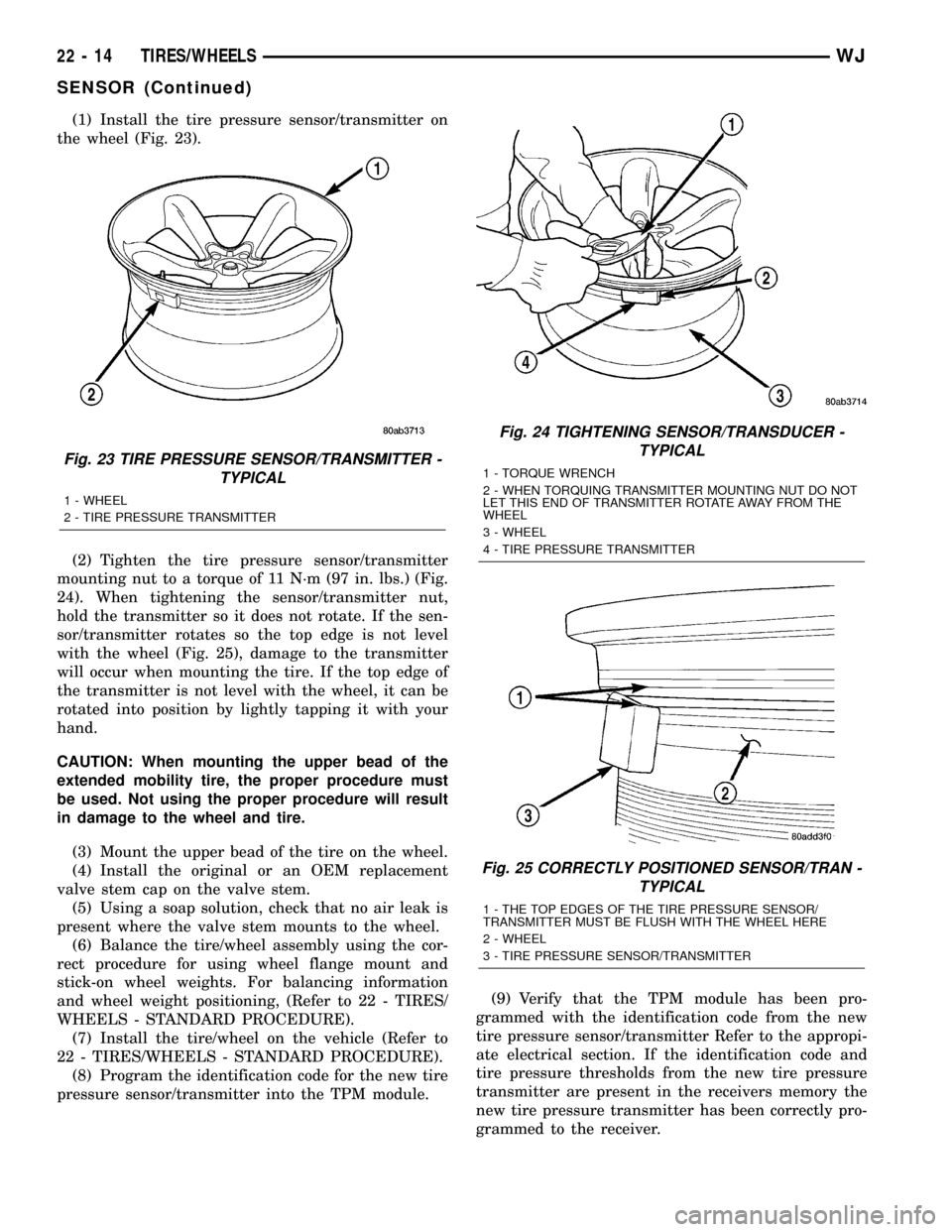
(1) Install the tire pressure sensor/transmitter on
the wheel (Fig. 23).
(2) Tighten the tire pressure sensor/transmitter
mounting nut to a torque of 11 N´m (97 in. lbs.) (Fig.
24). When tightening the sensor/transmitter nut,
hold the transmitter so it does not rotate. If the sen-
sor/transmitter rotates so the top edge is not level
with the wheel (Fig. 25), damage to the transmitter
will occur when mounting the tire. If the top edge of
the transmitter is not level with the wheel, it can be
rotated into position by lightly tapping it with your
hand.
CAUTION: When mounting the upper bead of the
extended mobility tire, the proper procedure must
be used. Not using the proper procedure will result
in damage to the wheel and tire.
(3) Mount the upper bead of the tire on the wheel.
(4) Install the original or an OEM replacement
valve stem cap on the valve stem.
(5) Using a soap solution, check that no air leak is
present where the valve stem mounts to the wheel.
(6) Balance the tire/wheel assembly using the cor-
rect procedure for using wheel flange mount and
stick-on wheel weights. For balancing information
and wheel weight positioning, (Refer to 22 - TIRES/
WHEELS - STANDARD PROCEDURE).
(7) Install the tire/wheel on the vehicle (Refer to
22 - TIRES/WHEELS - STANDARD PROCEDURE).
(8) Program the identification code for the new tire
pressure sensor/transmitter into the TPM module.(9) Verify that the TPM module has been pro-
grammed with the identification code from the new
tire pressure sensor/transmitter Refer to the appropi-
ate electrical section. If the identification code and
tire pressure thresholds from the new tire pressure
transmitter are present in the receivers memory the
new tire pressure transmitter has been correctly pro-
grammed to the receiver.
Fig. 23 TIRE PRESSURE SENSOR/TRANSMITTER -
TYPICAL
1 - WHEEL
2 - TIRE PRESSURE TRANSMITTER
Fig. 24 TIGHTENING SENSOR/TRANSDUCER -
TYPICAL
1 - TORQUE WRENCH
2 - WHEN TORQUING TRANSMITTER MOUNTING NUT DO NOT
LET THIS END OF TRANSMITTER ROTATE AWAY FROM THE
WHEEL
3 - WHEEL
4 - TIRE PRESSURE TRANSMITTER
Fig. 25 CORRECTLY POSITIONED SENSOR/TRAN -
TYPICAL
1 - THE TOP EDGES OF THE TIRE PRESSURE SENSOR/
TRANSMITTER MUST BE FLUSH WITH THE WHEEL HERE
2 - WHEEL
3 - TIRE PRESSURE SENSOR/TRANSMITTER
22 - 14 TIRES/WHEELSWJ
SENSOR (Continued)
Page 1922 of 2199
GLOVE BOX LATCH STRIKER
REMOVAL
WARNING: ON VEHICLES EQUIPPED WITH AIR-
BAGS, DISABLE THE AIRBAG SYSTEM BEFORE
ATTEMPTING ANY STEERING WHEEL, STEERING
COLUMN, OR INSTRUMENT PANEL COMPONENT
DIAGNOSIS OR SERVICE. DISCONNECT AND ISO-
LATE THE BATTERY NEGATIVE (GROUND) CABLE,
THEN WAIT TWO MINUTES FOR THE AIRBAG SYS-
TEM CAPACITOR TO DISCHARGE BEFORE PER-
FORMING FURTHER DIAGNOSIS OR SERVICE. THIS
IS THE ONLY SURE WAY TO DISABLE THE AIRBAG
SYSTEM. FAILURE TO TAKE THE PROPER PRE-
CAUTIONS COULD RESULT IN ACCIDENTAL AIR-
BAG DEPLOYMENT AND POSSIBLE PERSONAL
INJURY.
(1) Disconnect and isolate the battery negative
cable.
(2) If the inboard glove box latch striker is being
serviced, remove the lower right center bezel from
the instrument panel. (Refer to 23 - BODY/INSTRU-
MENT PANEL/IP LOWER RIGHT CENTER BEZEL
- REMOVAL). If the outboard glove box latch striker
is being serviced, remove the end cap from the
instrument panel. (Refer to 23 - BODY/INSTRU-
MENT PANEL/INSTRUMENT PANEL END CAP -
REMOVAL).
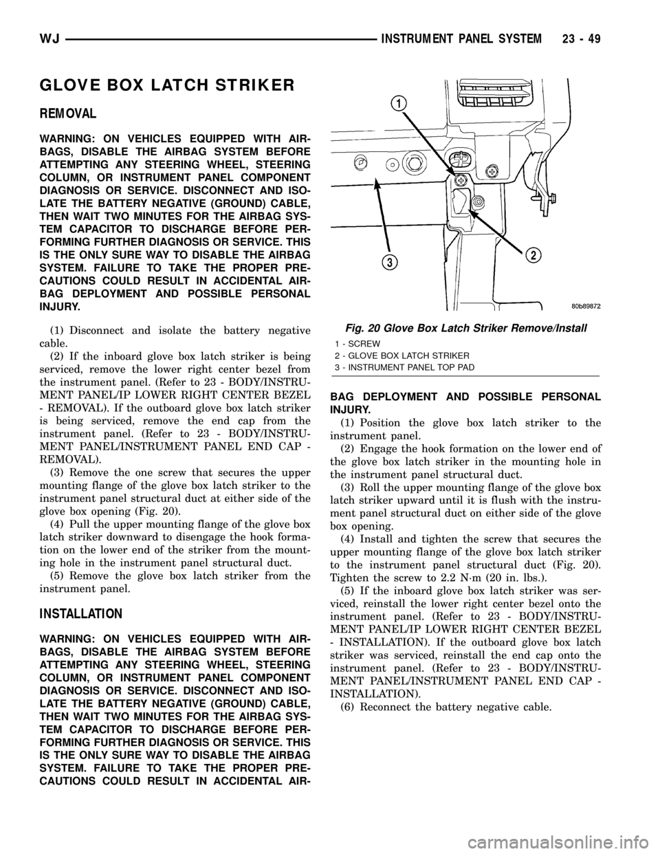
(3) Remove the one screw that secures the upper
mounting flange of the glove box latch striker to the
instrument panel structural duct at either side of the
glove box opening (Fig. 20).
(4) Pull the upper mounting flange of the glove box
latch striker downward to disengage the hook forma-
tion on the lower end of the striker from the mount-
ing hole in the instrument panel structural duct.
(5) Remove the glove box latch striker from the
instrument panel.
INSTALLATION
WARNING: ON VEHICLES EQUIPPED WITH AIR-
BAGS, DISABLE THE AIRBAG SYSTEM BEFORE
ATTEMPTING ANY STEERING WHEEL, STEERING
COLUMN, OR INSTRUMENT PANEL COMPONENT
DIAGNOSIS OR SERVICE. DISCONNECT AND ISO-
LATE THE BATTERY NEGATIVE (GROUND) CABLE,
THEN WAIT TWO MINUTES FOR THE AIRBAG SYS-
TEM CAPACITOR TO DISCHARGE BEFORE PER-
FORMING FURTHER DIAGNOSIS OR SERVICE. THIS
IS THE ONLY SURE WAY TO DISABLE THE AIRBAG
SYSTEM. FAILURE TO TAKE THE PROPER PRE-
CAUTIONS COULD RESULT IN ACCIDENTAL AIR-BAG DEPLOYMENT AND POSSIBLE PERSONAL
INJURY.
(1) Position the glove box latch striker to the
instrument panel.
(2) Engage the hook formation on the lower end of
the glove box latch striker in the mounting hole in
the instrument panel structural duct.
(3) Roll the upper mounting flange of the glove box
latch striker upward until it is flush with the instru-
ment panel structural duct on either side of the glove
box opening.
(4) Install and tighten the screw that secures the
upper mounting flange of the glove box latch striker
to the instrument panel structural duct (Fig. 20).
Tighten the screw to 2.2 N´m (20 in. lbs.).
(5) If the inboard glove box latch striker was ser-
viced, reinstall the lower right center bezel onto the
instrument panel. (Refer to 23 - BODY/INSTRU-
MENT PANEL/IP LOWER RIGHT CENTER BEZEL
- INSTALLATION). If the outboard glove box latch
striker was serviced, reinstall the end cap onto the
instrument panel. (Refer to 23 - BODY/INSTRU-
MENT PANEL/INSTRUMENT PANEL END CAP -
INSTALLATION).
(6) Reconnect the battery negative cable.
Fig. 20 Glove Box Latch Striker Remove/Install
1 - SCREW
2 - GLOVE BOX LATCH STRIKER
3 - INSTRUMENT PANEL TOP PAD
WJINSTRUMENT PANEL SYSTEM 23 - 49
Page 1968 of 2199
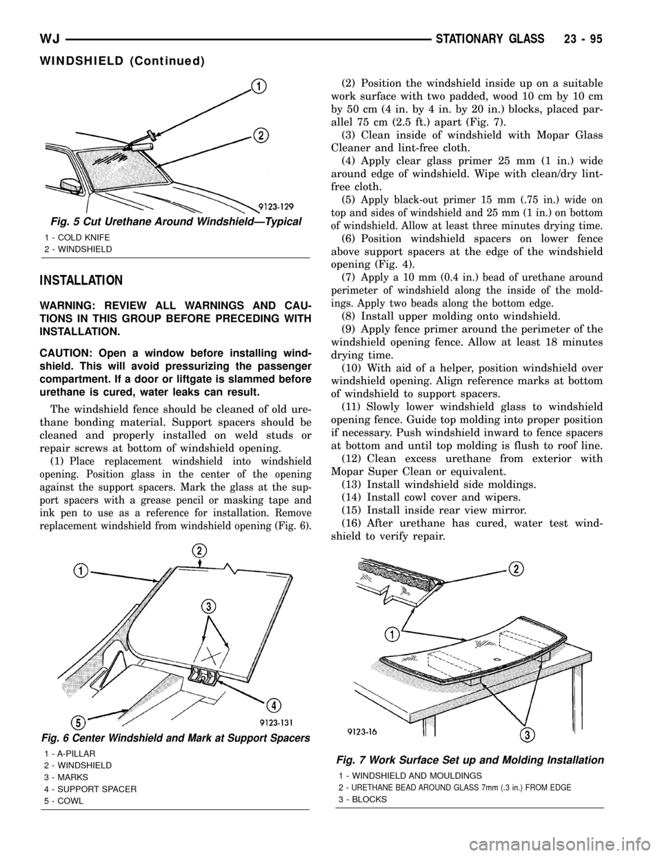
INSTALLATION
WARNING: REVIEW ALL WARNINGS AND CAU-
TIONS IN THIS GROUP BEFORE PRECEDING WITH
INSTALLATION.
CAUTION: Open a window before installing wind-
shield. This will avoid pressurizing the passenger
compartment. If a door or liftgate is slammed before
urethane is cured, water leaks can result.
The windshield fence should be cleaned of old ure-
thane bonding material. Support spacers should be
cleaned and properly installed on weld studs or
repair screws at bottom of windshield opening.
(1)
Place replacement windshield into windshield
opening. Position glass in the center of the opening
against the support spacers. Mark the glass at the sup-
port spacers with a grease pencil or masking tape and
ink pen to use as a reference for installation. Remove
replacement windshield from windshield opening (Fig. 6).
(2) Position the windshield inside up on a suitable
work surface with two padded, wood 10 cm by 10 cm
by 50 cm (4 in. by 4 in. by 20 in.) blocks, placed par-
allel 75 cm (2.5 ft.) apart (Fig. 7).
(3) Clean inside of windshield with Mopar Glass
Cleaner and lint-free cloth.
(4) Apply clear glass primer 25 mm (1 in.) wide
around edge of windshield. Wipe with clean/dry lint-
free cloth.
(5)
Apply black-out primer 15 mm (.75 in.) wide on
top and sides of windshield and 25 mm (1 in.) on bottom
of windshield. Allow at least three minutes drying time.
(6) Position windshield spacers on lower fence
above support spacers at the edge of the windshield
opening (Fig. 4).
(7)
Apply a 10 mm (0.4 in.) bead of urethane around
perimeter of windshield along the inside of the mold-
ings. Apply two beads along the bottom edge.
(8) Install upper molding onto windshield.
(9) Apply fence primer around the perimeter of the
windshield opening fence. Allow at least 18 minutes
drying time.
(10) With aid of a helper, position windshield over
windshield opening. Align reference marks at bottom
of windshield to support spacers.
(11) Slowly lower windshield glass to windshield
opening fence. Guide top molding into proper position
if necessary. Push windshield inward to fence spacers
at bottom and until top molding is flush to roof line.
(12) Clean excess urethane from exterior with
Mopar Super Clean or equivalent.
(13) Install windshield side moldings.
(14) Install cowl cover and wipers.
(15) Install inside rear view mirror.
(16) After urethane has cured, water test wind-
shield to verify repair.
Fig. 6 Center Windshield and Mark at Support Spacers
1 - A-PILLAR
2 - WINDSHIELD
3 - MARKS
4 - SUPPORT SPACER
5 - COWLFig. 7 Work Surface Set up and Molding Installation
1 - WINDSHIELD AND MOULDINGS
2-
URETHANE BEAD AROUND GLASS 7mm (.3 in.) FROM EDGE
3 - BLOCKS
Fig. 5 Cut Urethane Around WindshieldÐTypical
1 - COLD KNIFE
2 - WINDSHIELD
WJSTATIONARY GLASS 23 - 95
WINDSHIELD (Continued)
Page 1970 of 2199
releasing the control switch before the sunroof was
fully closed. The sunroof module has a water-man-
agement system. During washing high-pressure
water may be forced between the glass panel seal
and the roof opening. Normally this water will drain.
However, when some type of drying blower system is
used, like those found in automatic car washes, thewater may not have a chance to drain before the
blower forces air between the seal and the roof open-
ing. This causes the water to blow over the edge of
the module and onto the headlining.
Refer to (Fig. 1) Sunroof Assembly for exploded
view of the sunroof.
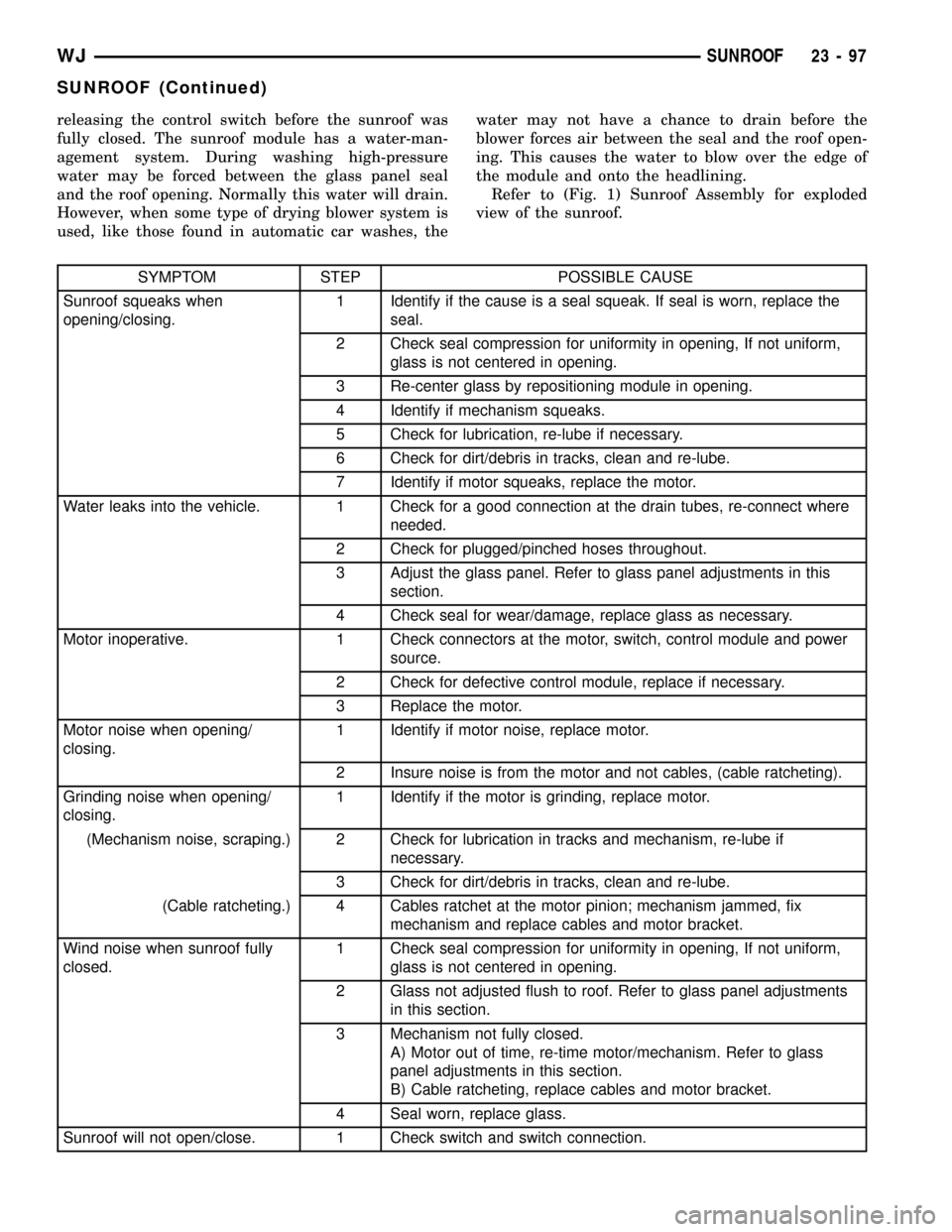
SYMPTOM STEP POSSIBLE CAUSE
Sunroof squeaks when
opening/closing.1 Identify if the cause is a seal squeak. If seal is worn, replace the
seal.
2 Check seal compression for uniformity in opening, If not uniform,
glass is not centered in opening.
3 Re-center glass by repositioning module in opening.
4 Identify if mechanism squeaks.
5 Check for lubrication, re-lube if necessary.
6 Check for dirt/debris in tracks, clean and re-lube.
7 Identify if motor squeaks, replace the motor.
Water leaks into the vehicle. 1 Check for a good connection at the drain tubes, re-connect where
needed.
2 Check for plugged/pinched hoses throughout.
3 Adjust the glass panel. Refer to glass panel adjustments in this
section.
4 Check seal for wear/damage, replace glass as necessary.
Motor inoperative. 1 Check connectors at the motor, switch, control module and power
source.
2 Check for defective control module, replace if necessary.
3 Replace the motor.
Motor noise when opening/
closing.1 Identify if motor noise, replace motor.
2 Insure noise is from the motor and not cables, (cable ratcheting).
Grinding noise when opening/
closing.1 Identify if the motor is grinding, replace motor.
(Mechanism noise, scraping.) 2 Check for lubrication in tracks and mechanism, re-lube if
necessary.
3 Check for dirt/debris in tracks, clean and re-lube.
(Cable ratcheting.) 4 Cables ratchet at the motor pinion; mechanism jammed, fix
mechanism and replace cables and motor bracket.
Wind noise when sunroof fully
closed.1 Check seal compression for uniformity in opening, If not uniform,
glass is not centered in opening.
2 Glass not adjusted flush to roof. Refer to glass panel adjustments
in this section.
3 Mechanism not fully closed.
A) Motor out of time, re-time motor/mechanism. Refer to glass
panel adjustments in this section.
B) Cable ratcheting, replace cables and motor bracket.
4 Seal worn, replace glass.
Sunroof will not open/close. 1 Check switch and switch connection.
WJSUNROOF 23 - 97
SUNROOF (Continued)
Page 1976 of 2199
INSTALLATION
NOTE: Sunroof glass must be set in place and
attached as close as possible to flush with the roof
surface. For wind noise reasons, care must be
taken to ensure that the glass is not remounted
either a) Overflush to the roof surface at the front
edge of the glass, or b) Underflush to the roof sur-
face at the rear edge of the glass.
(1) Position glass panel in to opening.
(2) Start the four attaching screws.
(3) Tighten screws.
(4) Verify sunroof operation and alignment. Check
fit and adjust as necessary. (Refer to 23 - BODY/
SUNROOF/GLASS PANEL - ADJUSTMENTS - FIT)
ADJUSTMENTS
ADJUSTMENTS - FIT
(1) Move the sunshade rearward to the open posi-
tion.
(2) Move the sunroof glass panel to the fully closed
position.
(3) Loosen the forward screws on each side enough
to make the front adjustment.
(4) Adjust the front of the sunroof glass panel 1
mm (1/32 inch) below the top surface of the roof
panel.
(5) Tighten the front two screws.
(6) Loosen the rear screws on each side enough to
make the rear adjustment.
(7) Adjust the rear of the sunroof glass panel 1
mm (1/32 inch) above the top surface of the roof
panel.
(8) Tighten the rear two screws.
(9) Check for proper fit. If not OK, repeat glass
panel adjustment.
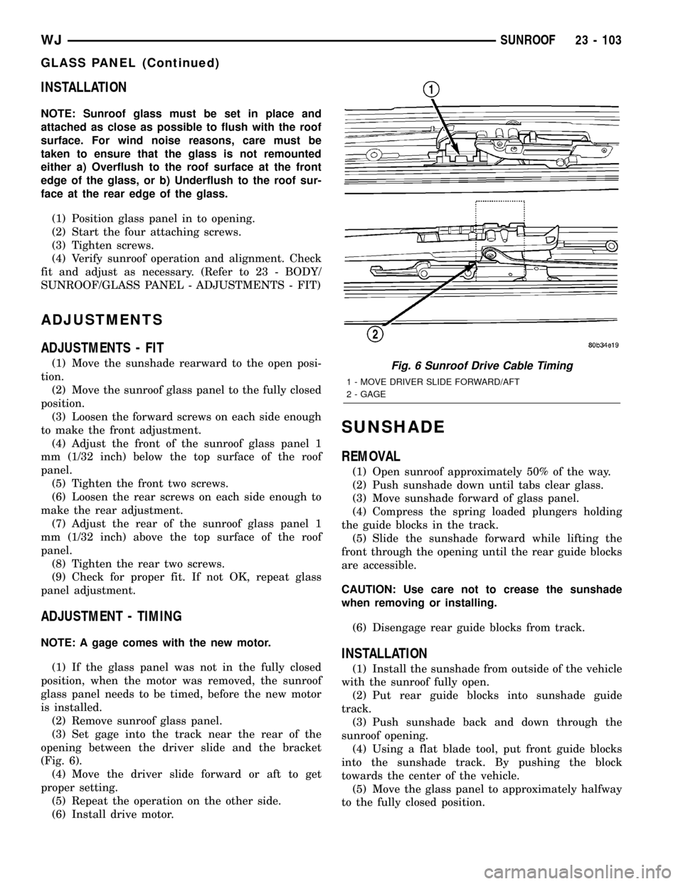
ADJUSTMENT - TIMING
NOTE: A gage comes with the new motor.
(1) If the glass panel was not in the fully closed
position, when the motor was removed, the sunroof
glass panel needs to be timed, before the new motor
is installed.
(2) Remove sunroof glass panel.
(3) Set gage into the track near the rear of the
opening between the driver slide and the bracket
(Fig. 6).
(4) Move the driver slide forward or aft to get
proper setting.
(5) Repeat the operation on the other side.
(6) Install drive motor.
SUNSHADE
REMOVAL
(1) Open sunroof approximately 50% of the way.
(2) Push sunshade down until tabs clear glass.
(3) Move sunshade forward of glass panel.
(4) Compress the spring loaded plungers holding
the guide blocks in the track.
(5) Slide the sunshade forward while lifting the
front through the opening until the rear guide blocks
are accessible.
CAUTION: Use care not to crease the sunshade
when removing or installing.
(6) Disengage rear guide blocks from track.
INSTALLATION
(1) Install the sunshade from outside of the vehicle
with the sunroof fully open.
(2) Put rear guide blocks into sunshade guide
track.
(3) Push sunshade back and down through the
sunroof opening.
(4) Using a flat blade tool, put front guide blocks
into the sunshade track. By pushing the block
towards the center of the vehicle.
(5) Move the glass panel to approximately halfway
to the fully closed position.
Fig. 6 Sunroof Drive Cable Timing
1 - MOVE DRIVER SLIDE FORWARD/AFT
2 - GAGE
WJSUNROOF 23 - 103
GLASS PANEL (Continued)
Page 1984 of 2199
BODY STRUCTURE
TABLE OF CONTENTS
page page
GAP AND FLUSH
SPECIFICATIONS - GAP AND FLUSH.......112
OPENING DIMENSIONS
SPECIFICATIONS - BODY OPENING
DIMENSIONS........................114
SEALER LOCATIONS
SPECIFICATIONS
SEALER LOCATIONS.................118STUCTURAL ADHESIVE LOCATIONS
SPECIFICATIONS - STRUCTURAL ADHESIVE
LOCATIONS.........................137
WELD LOCATIONS
SPECIFICATIONS
WELD LOCATIONS...................153
GAP AND FLUSH
SPECIFICATIONS - GAP AND FLUSH
DESCIPTION FIGURE
FRONT VIEW 1
REAR VIEW 2
23 - 112 BODY STRUCTUREWJ