2003 JEEP GRAND CHEROKEE seat motor
[x] Cancel search: seat motorPage 1153 of 2199
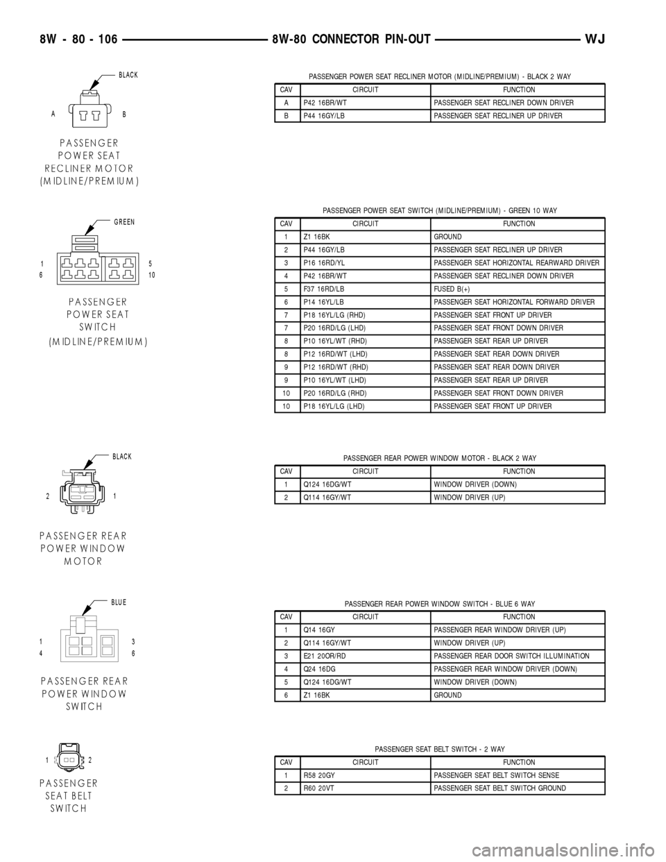
PASSENGER POWER SEAT RECLINER MOTOR (MIDLINE/PREMIUM) - BLACK 2 WAY
CAV CIRCUIT FUNCTION
A P42 16BR/WT PASSENGER SEAT RECLINER DOWN DRIVER
B P44 16GY/LB PASSENGER SEAT RECLINER UP DRIVER
PASSENGER POWER SEAT SWITCH (MIDLINE/PREMIUM) - GREEN 10 WAY
CAV CIRCUIT FUNCTION
1 Z1 16BK GROUND
2 P44 16GY/LB PASSENGER SEAT RECLINER UP DRIVER
3 P16 16RD/YL PASSENGER SEAT HORIZONTAL REARWARD DRIVER
4 P42 16BR/WT PASSENGER SEAT RECLINER DOWN DRIVER
5 F37 16RD/LB FUSED B(+)
6 P14 16YL/LB PASSENGER SEAT HORIZONTAL FORWARD DRIVER
7 P18 16YL/LG (RHD) PASSENGER SEAT FRONT UP DRIVER
7 P20 16RD/LG (LHD) PASSENGER SEAT FRONT DOWN DRIVER
8 P10 16YL/WT (RHD) PASSENGER SEAT REAR UP DRIVER
8 P12 16RD/WT (LHD) PASSENGER SEAT REAR DOWN DRIVER
9 P12 16RD/WT (RHD) PASSENGER SEAT REAR DOWN DRIVER
9 P10 16YL/WT (LHD) PASSENGER SEAT REAR UP DRIVER
10 P20 16RD/LG (RHD) PASSENGER SEAT FRONT DOWN DRIVER
10 P18 16YL/LG (LHD) PASSENGER SEAT FRONT UP DRIVER
PASSENGER REAR POWER WINDOW MOTOR - BLACK 2 WAY
CAV CIRCUIT FUNCTION
1 Q124 16DG/WT WINDOW DRIVER (DOWN)
2 Q114 16GY/WT WINDOW DRIVER (UP)
PASSENGER REAR POWER WINDOW SWITCH - BLUE 6 WAY
CAV CIRCUIT FUNCTION
1 Q14 16GY PASSENGER REAR WINDOW DRIVER (UP)
2 Q114 16GY/WT WINDOW DRIVER (UP)
3 E21 20OR/RD PASSENGER REAR DOOR SWITCH ILLUMINATION
4 Q24 16DG PASSENGER REAR WINDOW DRIVER (DOWN)
5 Q124 16DG/WT WINDOW DRIVER (DOWN)
6 Z1 16BK GROUND
PASSENGER SEAT BELT SWITCH-2WAY
CAV CIRCUIT FUNCTION
1 R58 20GY PASSENGER SEAT BELT SWITCH SENSE
2 R60 20VT PASSENGER SEAT BELT SWITCH GROUND
8W - 80 - 106 8W-80 CONNECTOR PIN-OUTWJ
Page 1179 of 2199
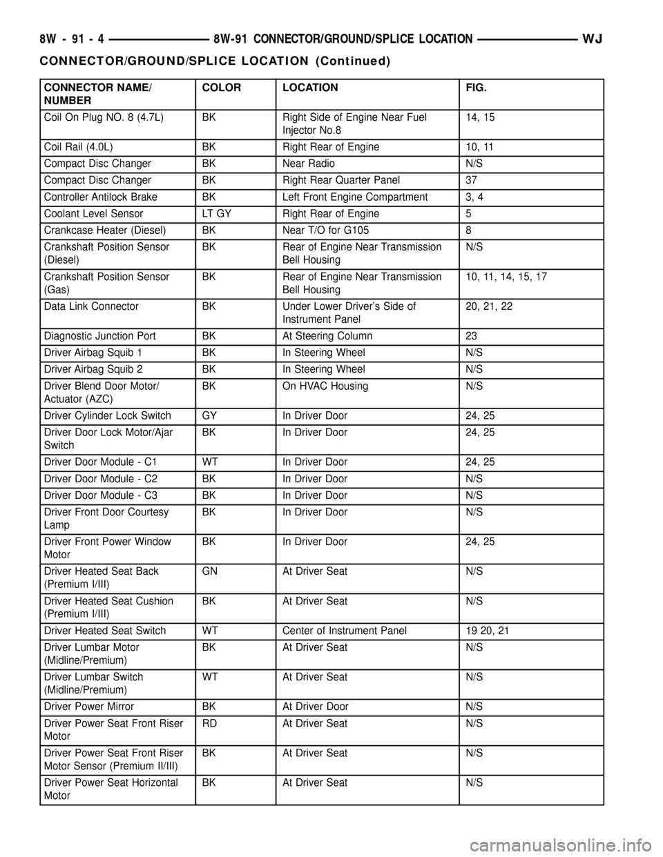
CONNECTOR NAME/
NUMBERCOLOR LOCATION FIG.
Coil On Plug NO. 8 (4.7L) BK Right Side of Engine Near Fuel
Injector No.814, 15
Coil Rail (4.0L) BK Right Rear of Engine 10, 11
Compact Disc Changer BK Near Radio N/S
Compact Disc Changer BK Right Rear Quarter Panel 37
Controller Antilock Brake BK Left Front Engine Compartment 3, 4
Coolant Level Sensor LT GY Right Rear of Engine 5
Crankcase Heater (Diesel) BK Near T/O for G105 8
Crankshaft Position Sensor
(Diesel)BK Rear of Engine Near Transmission
Bell HousingN/S
Crankshaft Position Sensor
(Gas)BK Rear of Engine Near Transmission
Bell Housing10, 11, 14, 15, 17
Data Link Connector BK Under Lower Driver's Side of
Instrument Panel20, 21, 22
Diagnostic Junction Port BK At Steering Column 23
Driver Airbag Squib 1 BK In Steering Wheel N/S
Driver Airbag Squib 2 BK In Steering Wheel N/S
Driver Blend Door Motor/
Actuator (AZC)BK On HVAC Housing N/S
Driver Cylinder Lock Switch GY In Driver Door 24, 25
Driver Door Lock Motor/Ajar
SwitchBK In Driver Door 24, 25
Driver Door Module - C1 WT In Driver Door 24, 25
Driver Door Module - C2 BK In Driver Door N/S
Driver Door Module - C3 BK In Driver Door N/S
Driver Front Door Courtesy
LampBK In Driver Door N/S
Driver Front Power Window
MotorBK In Driver Door 24, 25
Driver Heated Seat Back
(Premium I/III)GN At Driver Seat N/S
Driver Heated Seat Cushion
(Premium I/III)BK At Driver Seat N/S
Driver Heated Seat Switch WT Center of Instrument Panel 19 20, 21
Driver Lumbar Motor
(Midline/Premium)BK At Driver Seat N/S
Driver Lumbar Switch
(Midline/Premium)WT At Driver Seat N/S
Driver Power Mirror BK At Driver Door N/S
Driver Power Seat Front Riser
MotorRD At Driver Seat N/S
Driver Power Seat Front Riser
Motor Sensor (Premium II/III)BK At Driver Seat N/S
Driver Power Seat Horizontal
MotorBK At Driver Seat N/S
8W - 91 - 4 8W-91 CONNECTOR/GROUND/SPLICE LOCATIONWJ
CONNECTOR/GROUND/SPLICE LOCATION (Continued)
Page 1180 of 2199
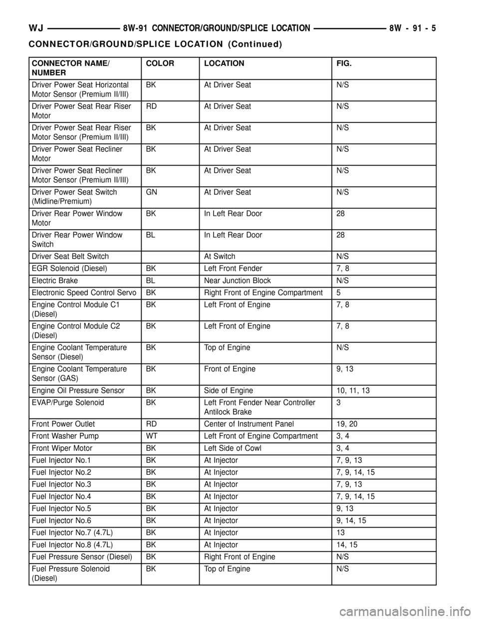
CONNECTOR NAME/
NUMBERCOLOR LOCATION FIG.
Driver Power Seat Horizontal
Motor Sensor (Premium II/III)BK At Driver Seat N/S
Driver Power Seat Rear Riser
MotorRD At Driver Seat N/S
Driver Power Seat Rear Riser
Motor Sensor (Premium II/III)BK At Driver Seat N/S
Driver Power Seat Recliner
MotorBK At Driver Seat N/S
Driver Power Seat Recliner
Motor Sensor (Premium II/III)BK At Driver Seat N/S
Driver Power Seat Switch
(Midline/Premium)GN At Driver Seat N/S
Driver Rear Power Window
MotorBK In Left Rear Door 28
Driver Rear Power Window
SwitchBL In Left Rear Door 28
Driver Seat Belt Switch At Switch N/S
EGR Solenoid (Diesel) BK Left Front Fender 7, 8
Electric Brake BL Near Junction Block N/S
Electronic Speed Control Servo BK Right Front of Engine Compartment 5
Engine Control Module C1
(Diesel)BK Left Front of Engine 7, 8
Engine Control Module C2
(Diesel)BK Left Front of Engine 7, 8
Engine Coolant Temperature
Sensor (Diesel)BK Top of Engine N/S
Engine Coolant Temperature
Sensor (GAS)BK Front of Engine 9, 13
Engine Oil Pressure Sensor BK Side of Engine 10, 11, 13
EVAP/Purge Solenoid BK Left Front Fender Near Controller
Antilock Brake3
Front Power Outlet RD Center of Instrument Panel 19, 20
Front Washer Pump WT Left Front of Engine Compartment 3, 4
Front Wiper Motor BK Left Side of Cowl 3, 4
Fuel Injector No.1 BK At Injector 7, 9, 13
Fuel Injector No.2 BK At Injector 7, 9, 14, 15
Fuel Injector No.3 BK At Injector 7, 9, 13
Fuel Injector No.4 BK At Injector 7, 9, 14, 15
Fuel Injector No.5 BK At Injector 9, 13
Fuel Injector No.6 BK At Injector 9, 14, 15
Fuel Injector No.7 (4.7L) BK At Injector 13
Fuel Injector No.8 (4.7L) BK At Injector 14, 15
Fuel Pressure Sensor (Diesel) BK Right Front of Engine N/S
Fuel Pressure Solenoid
(Diesel)BK Top of Engine N/S
WJ8W-91 CONNECTOR/GROUND/SPLICE LOCATION 8W - 91 - 5
CONNECTOR/GROUND/SPLICE LOCATION (Continued)
Page 1183 of 2199
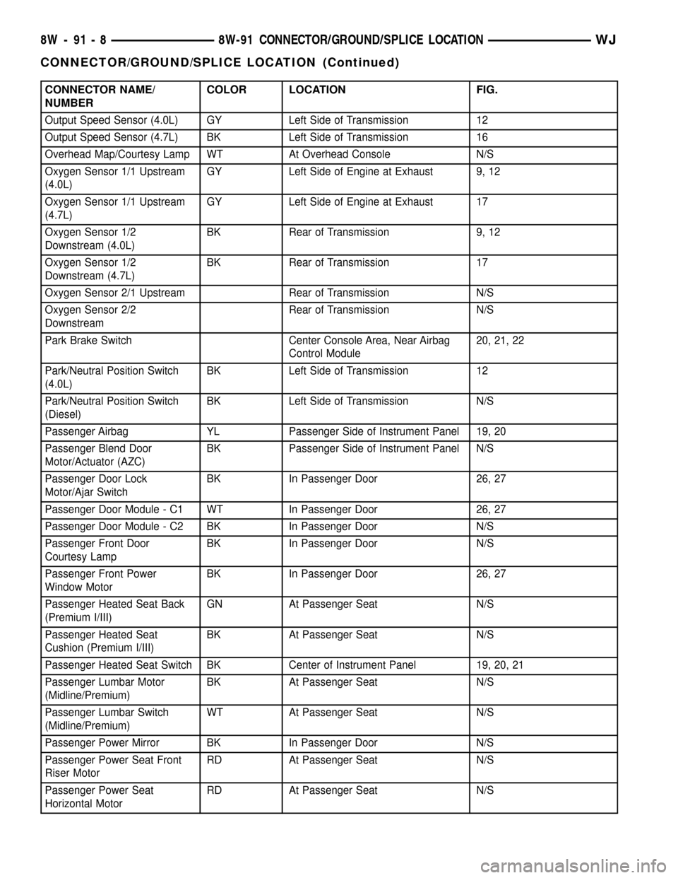
CONNECTOR NAME/
NUMBERCOLOR LOCATION FIG.
Output Speed Sensor (4.0L) GY Left Side of Transmission 12
Output Speed Sensor (4.7L) BK Left Side of Transmission 16
Overhead Map/Courtesy Lamp WT At Overhead Console N/S
Oxygen Sensor 1/1 Upstream
(4.0L)GY Left Side of Engine at Exhaust 9, 12
Oxygen Sensor 1/1 Upstream
(4.7L)GY Left Side of Engine at Exhaust 17
Oxygen Sensor 1/2
Downstream (4.0L)BK Rear of Transmission 9, 12
Oxygen Sensor 1/2
Downstream (4.7L)BK Rear of Transmission 17
Oxygen Sensor 2/1 Upstream Rear of Transmission N/S
Oxygen Sensor 2/2
DownstreamRear of Transmission N/S
Park Brake Switch Center Console Area, Near Airbag
Control Module20, 21, 22
Park/Neutral Position Switch
(4.0L)BK Left Side of Transmission 12
Park/Neutral Position Switch
(Diesel)BK Left Side of Transmission N/S
Passenger Airbag YL Passenger Side of Instrument Panel 19, 20
Passenger Blend Door
Motor/Actuator (AZC)BK Passenger Side of Instrument Panel N/S
Passenger Door Lock
Motor/Ajar SwitchBK In Passenger Door 26, 27
Passenger Door Module - C1 WT In Passenger Door 26, 27
Passenger Door Module - C2 BK In Passenger Door N/S
Passenger Front Door
Courtesy LampBK In Passenger Door N/S
Passenger Front Power
Window MotorBK In Passenger Door 26, 27
Passenger Heated Seat Back
(Premium I/III)GN At Passenger Seat N/S
Passenger Heated Seat
Cushion (Premium I/III)BK At Passenger Seat N/S
Passenger Heated Seat Switch BK Center of Instrument Panel 19, 20, 21
Passenger Lumbar Motor
(Midline/Premium)BK At Passenger Seat N/S
Passenger Lumbar Switch
(Midline/Premium)WT At Passenger Seat N/S
Passenger Power Mirror BK In Passenger Door N/S
Passenger Power Seat Front
Riser MotorRD At Passenger Seat N/S
Passenger Power Seat
Horizontal MotorRD At Passenger Seat N/S
8W - 91 - 8 8W-91 CONNECTOR/GROUND/SPLICE LOCATIONWJ
CONNECTOR/GROUND/SPLICE LOCATION (Continued)
Page 1184 of 2199
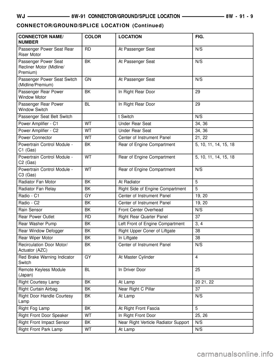
CONNECTOR NAME/
NUMBERCOLOR LOCATION FIG.
Passenger Power Seat Rear
Riser MotorRD At Passenger Seat N/S
Passenger Power Seat
Recliner Motor (Midline/
Premium)BK At Passenger Seat N/S
Passenger Power Seat Switch
(Midline/Premium)GN At Passenger Seat N/S
Passenger Rear Power
Window MotorBK In Right Rear Door 29
Passenger Rear Power
Window SwitchBL In Right Rear Door 29
Passenger Seat Belt Switch t Switch N/S
Power Amplifier - C1 WT Under Rear Seat 34, 36
Power Amplifier - C2 WT Under Rear Seat 34, 36
Power Connector WT Center of Instrument Panel 21, 22
Powertrain Control Module -
C1 (Gas)BK Rear of Engine Compartment 5, 10, 11, 14, 15, 18
Powertrain Control Module -
C2 (Gas)WT Rear of Engine Compartment 5, 10, 11, 14, 15, 18
Powertrain Control Module -
C3 (Gas)WT Rear of Engine Compartment N/S
Radiator Fan Motor BK At Radiator 5
Radiator Fan Relay BK Right Side of Engine Compartment 5
Radio - C1 GY Center of Instrument Panel 19, 20
Radio - C2 BK Center of Instrument Panel 19, 20
Rain Sensor BK Front Center Overhead N/S
Rear Power Outlet RD Right Rear Quarter Panel 37
Rear Washer Pump BK Left Front of Engine Compartment 3, 4
Rear Window Defogger BK Right Upper Coner of Liftgate 38
Rear Wiper Motor BK In Liftgate 38
Recirculation Door Motor/
Actuator (AZC)BK Center of Instrument Panel N/S
Red Brake Warning Indicator
SwitchGY At Master Cylinder 4
Remote Keyless Module
(Japan)BL In Driver Door 25
Right Courtesy Lamp BK At Lamp 20 21, 22
Right Curtain Airbag BK Near Right C Pillar 37
Right Door Handle Courtesy
LampBK At Lamp N/S
Right Fog Lamp BK At Right Front Fascia 5
Right Front Door Speaker WT In Right Front Door 25, 26
Right Front Impact Sensor BK Near Right Verticle Radiator Support N/S
Right Front Park Lamp WT At Lamp N/S
WJ8W-91 CONNECTOR/GROUND/SPLICE LOCATION 8W - 91 - 9
CONNECTOR/GROUND/SPLICE LOCATION (Continued)
Page 1185 of 2199
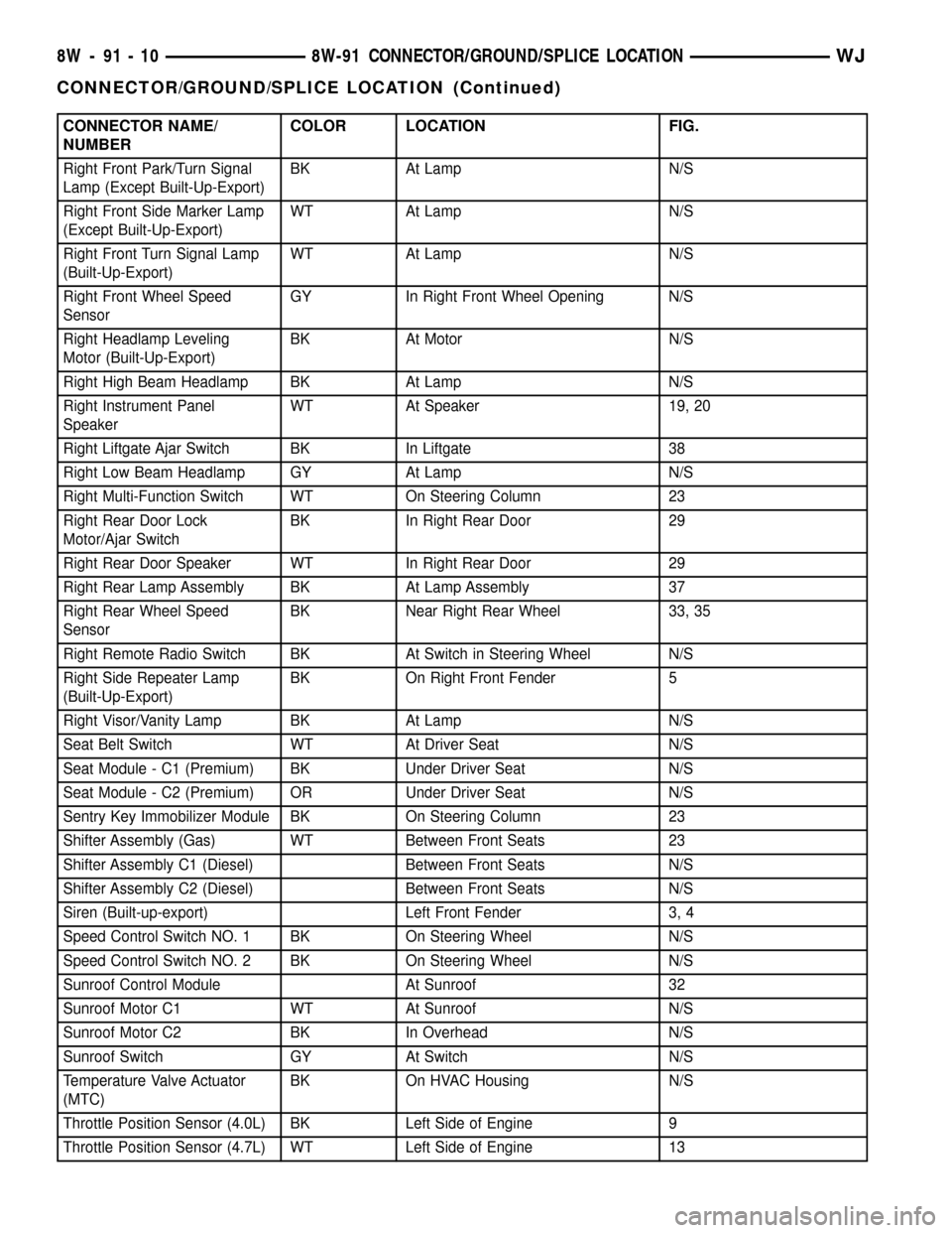
CONNECTOR NAME/
NUMBERCOLOR LOCATION FIG.
Right Front Park/Turn Signal
Lamp (Except Built-Up-Export)BK At Lamp N/S
Right Front Side Marker Lamp
(Except Built-Up-Export)WT At Lamp N/S
Right Front Turn Signal Lamp
(Built-Up-Export)WT At Lamp N/S
Right Front Wheel Speed
SensorGY In Right Front Wheel Opening N/S
Right Headlamp Leveling
Motor (Built-Up-Export)BK At Motor N/S
Right High Beam Headlamp BK At Lamp N/S
Right Instrument Panel
SpeakerWT At Speaker 19, 20
Right Liftgate Ajar Switch BK In Liftgate 38
Right Low Beam Headlamp GY At Lamp N/S
Right Multi-Function Switch WT On Steering Column 23
Right Rear Door Lock
Motor/Ajar SwitchBK In Right Rear Door 29
Right Rear Door Speaker WT In Right Rear Door 29
Right Rear Lamp Assembly BK At Lamp Assembly 37
Right Rear Wheel Speed
SensorBK Near Right Rear Wheel 33, 35
Right Remote Radio Switch BK At Switch in Steering Wheel N/S
Right Side Repeater Lamp
(Built-Up-Export)BK On Right Front Fender 5
Right Visor/Vanity Lamp BK At Lamp N/S
Seat Belt Switch WT At Driver Seat N/S
Seat Module - C1 (Premium) BK Under Driver Seat N/S
Seat Module - C2 (Premium) OR Under Driver Seat N/S
Sentry Key Immobilizer Module BK On Steering Column 23
Shifter Assembly (Gas) WT Between Front Seats 23
Shifter Assembly C1 (Diesel) Between Front Seats N/S
Shifter Assembly C2 (Diesel) Between Front Seats N/S
Siren (Built-up-export) Left Front Fender 3, 4
Speed Control Switch NO. 1 BK On Steering Wheel N/S
Speed Control Switch NO. 2 BK On Steering Wheel N/S
Sunroof Control Module At Sunroof 32
Sunroof Motor C1 WT At Sunroof N/S
Sunroof Motor C2 BK In Overhead N/S
Sunroof Switch GY At Switch N/S
Temperature Valve Actuator
(MTC)BK On HVAC Housing N/S
Throttle Position Sensor (4.0L) BK Left Side of Engine 9
Throttle Position Sensor (4.7L) WT Left Side of Engine 13
8W - 91 - 10 8W-91 CONNECTOR/GROUND/SPLICE LOCATIONWJ
CONNECTOR/GROUND/SPLICE LOCATION (Continued)
Page 1191 of 2199
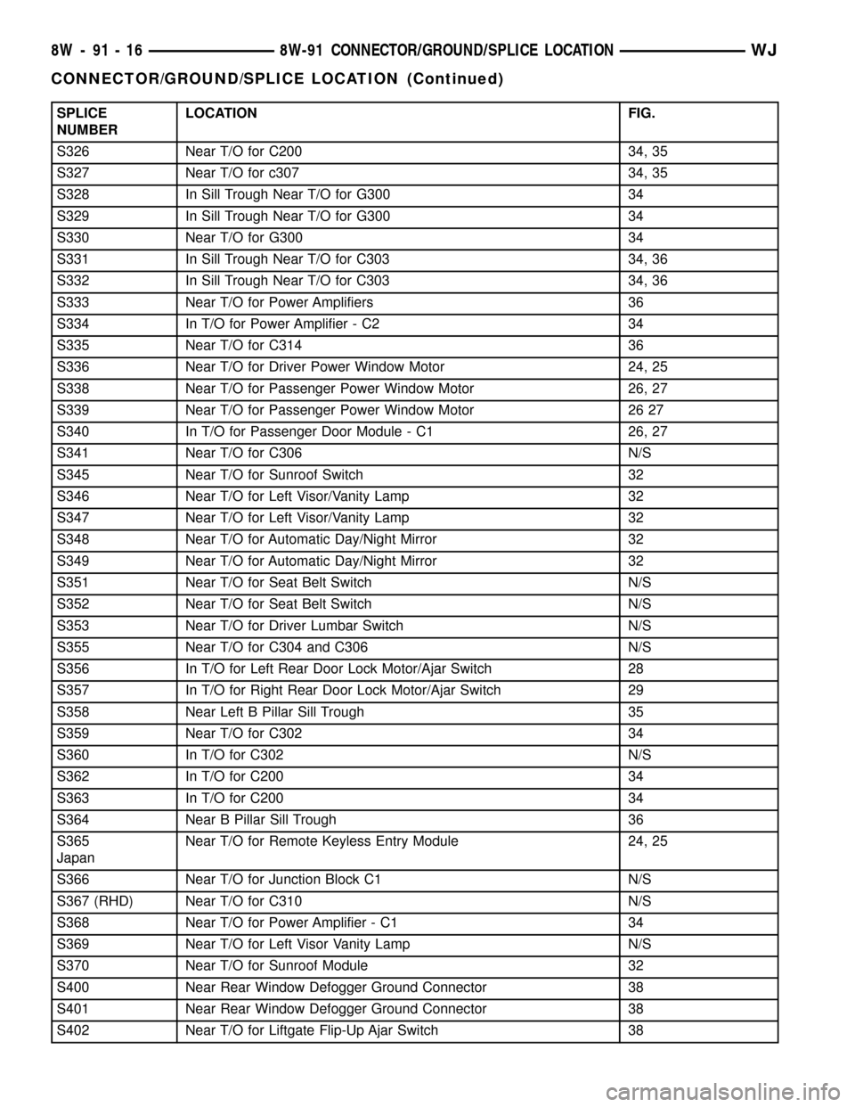
SPLICE
NUMBERLOCATION FIG.
S326 Near T/O for C200 34, 35
S327 Near T/O for c307 34, 35
S328 In Sill Trough Near T/O for G300 34
S329 In Sill Trough Near T/O for G300 34
S330 Near T/O for G300 34
S331 In Sill Trough Near T/O for C303 34, 36
S332 In Sill Trough Near T/O for C303 34, 36
S333 Near T/O for Power Amplifiers 36
S334 In T/O for Power Amplifier - C2 34
S335 Near T/O for C314 36
S336 Near T/O for Driver Power Window Motor 24, 25
S338 Near T/O for Passenger Power Window Motor 26, 27
S339 Near T/O for Passenger Power Window Motor 26 27
S340 In T/O for Passenger Door Module - C1 26, 27
S341 Near T/O for C306 N/S
S345 Near T/O for Sunroof Switch 32
S346 Near T/O for Left Visor/Vanity Lamp 32
S347 Near T/O for Left Visor/Vanity Lamp 32
S348 Near T/O for Automatic Day/Night Mirror 32
S349 Near T/O for Automatic Day/Night Mirror 32
S351 Near T/O for Seat Belt Switch N/S
S352 Near T/O for Seat Belt Switch N/S
S353 Near T/O for Driver Lumbar Switch N/S
S355 Near T/O for C304 and C306 N/S
S356 In T/O for Left Rear Door Lock Motor/Ajar Switch 28
S357 In T/O for Right Rear Door Lock Motor/Ajar Switch 29
S358 Near Left B Pillar Sill Trough 35
S359 Near T/O for C302 34
S360 In T/O for C302 N/S
S362 In T/O for C200 34
S363 In T/O for C200 34
S364 Near B Pillar Sill Trough 36
S365
JapanNear T/O for Remote Keyless Entry Module 24, 25
S366 Near T/O for Junction Block C1 N/S
S367 (RHD) Near T/O for C310 N/S
S368 Near T/O for Power Amplifier - C1 34
S369 Near T/O for Left Visor Vanity Lamp N/S
S370 Near T/O for Sunroof Module 32
S400 Near Rear Window Defogger Ground Connector 38
S401 Near Rear Window Defogger Ground Connector 38
S402 Near T/O for Liftgate Flip-Up Ajar Switch 38
8W - 91 - 16 8W-91 CONNECTOR/GROUND/SPLICE LOCATIONWJ
CONNECTOR/GROUND/SPLICE LOCATION (Continued)
Page 1251 of 2199
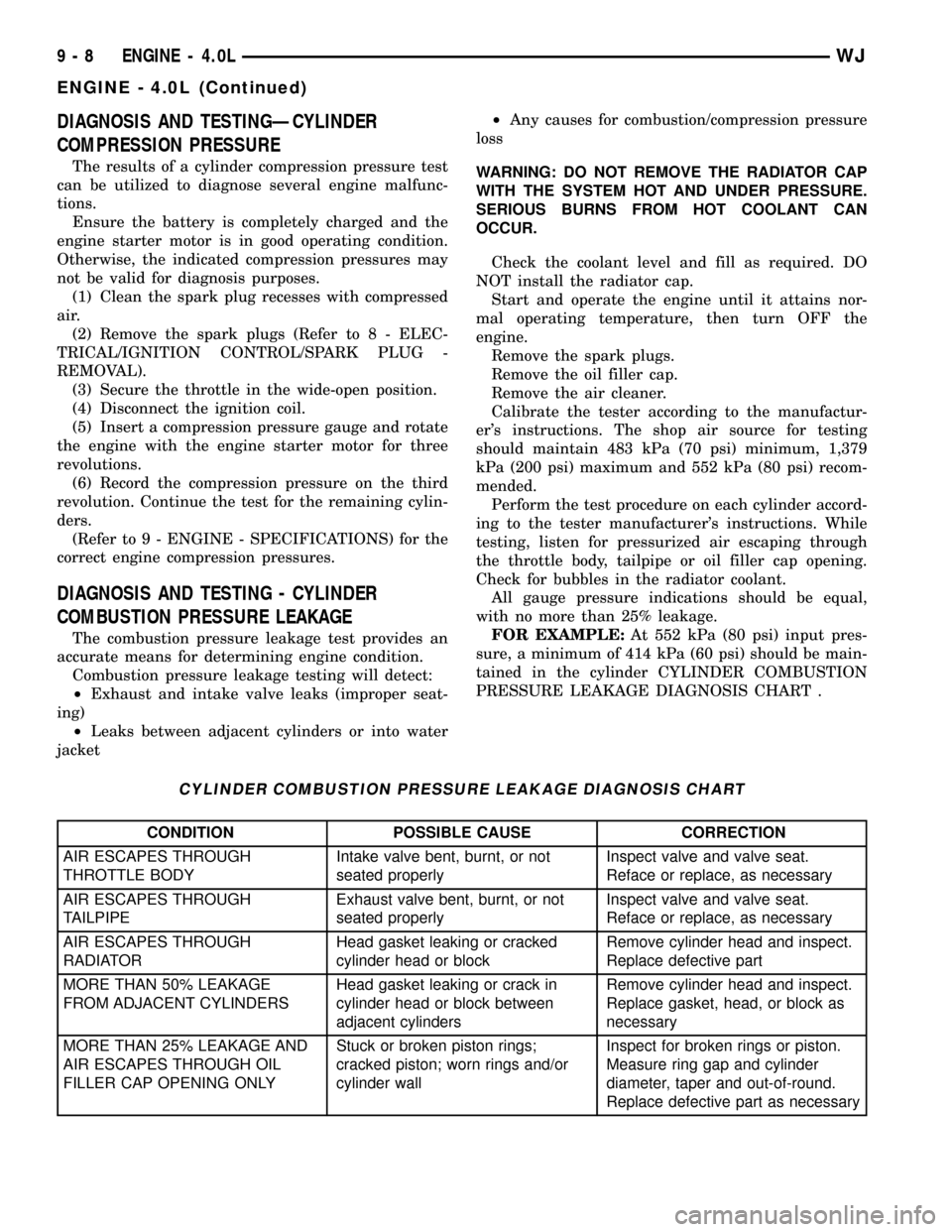
DIAGNOSIS AND TESTINGÐCYLINDER
COMPRESSION PRESSURE
The results of a cylinder compression pressure test
can be utilized to diagnose several engine malfunc-
tions.
Ensure the battery is completely charged and the
engine starter motor is in good operating condition.
Otherwise, the indicated compression pressures may
not be valid for diagnosis purposes.
(1) Clean the spark plug recesses with compressed
air.
(2) Remove the spark plugs (Refer to 8 - ELEC-
TRICAL/IGNITION CONTROL/SPARK PLUG -
REMOVAL).
(3) Secure the throttle in the wide-open position.
(4) Disconnect the ignition coil.
(5) Insert a compression pressure gauge and rotate
the engine with the engine starter motor for three
revolutions.
(6) Record the compression pressure on the third
revolution. Continue the test for the remaining cylin-
ders.
(Refer to 9 - ENGINE - SPECIFICATIONS) for the
correct engine compression pressures.
DIAGNOSIS AND TESTING - CYLINDER
COMBUSTION PRESSURE LEAKAGE
The combustion pressure leakage test provides an
accurate means for determining engine condition.
Combustion pressure leakage testing will detect:
²Exhaust and intake valve leaks (improper seat-
ing)
²Leaks between adjacent cylinders or into water
jacket²Any causes for combustion/compression pressure
loss
WARNING: DO NOT REMOVE THE RADIATOR CAP
WITH THE SYSTEM HOT AND UNDER PRESSURE.
SERIOUS BURNS FROM HOT COOLANT CAN
OCCUR.
Check the coolant level and fill as required. DO
NOT install the radiator cap.
Start and operate the engine until it attains nor-
mal operating temperature, then turn OFF the
engine.
Remove the spark plugs.
Remove the oil filler cap.
Remove the air cleaner.
Calibrate the tester according to the manufactur-
er's instructions. The shop air source for testing
should maintain 483 kPa (70 psi) minimum, 1,379
kPa (200 psi) maximum and 552 kPa (80 psi) recom-
mended.
Perform the test procedure on each cylinder accord-
ing to the tester manufacturer's instructions. While
testing, listen for pressurized air escaping through
the throttle body, tailpipe or oil filler cap opening.
Check for bubbles in the radiator coolant.
All gauge pressure indications should be equal,
with no more than 25% leakage.
FOR EXAMPLE:At 552 kPa (80 psi) input pres-
sure, a minimum of 414 kPa (60 psi) should be main-
tained in the cylinder CYLINDER COMBUSTION
PRESSURE LEAKAGE DIAGNOSIS CHART .
CYLINDER COMBUSTION PRESSURE LEAKAGE DIAGNOSIS CHART
CONDITION POSSIBLE CAUSE CORRECTION
AIR ESCAPES THROUGH
THROTTLE BODYIntake valve bent, burnt, or not
seated properlyInspect valve and valve seat.
Reface or replace, as necessary
AIR ESCAPES THROUGH
TAILPIPEExhaust valve bent, burnt, or not
seated properlyInspect valve and valve seat.
Reface or replace, as necessary
AIR ESCAPES THROUGH
RADIATORHead gasket leaking or cracked
cylinder head or blockRemove cylinder head and inspect.
Replace defective part
MORE THAN 50% LEAKAGE
FROM ADJACENT CYLINDERSHead gasket leaking or crack in
cylinder head or block between
adjacent cylindersRemove cylinder head and inspect.
Replace gasket, head, or block as
necessary
MORE THAN 25% LEAKAGE AND
AIR ESCAPES THROUGH OIL
FILLER CAP OPENING ONLYStuck or broken piston rings;
cracked piston; worn rings and/or
cylinder wallInspect for broken rings or piston.
Measure ring gap and cylinder
diameter, taper and out-of-round.
Replace defective part as necessary
9 - 8 ENGINE - 4.0LWJ
ENGINE - 4.0L (Continued)