2003 JEEP GRAND CHEROKEE fluid level check
[x] Cancel search: fluid level checkPage 1855 of 2199

(6) Connect front propeller shaft and install rear
propeller shaft. (Refer to 3 - DIFFERENTIAL &
DRIVELINE/PROPELLER SHAFT/PROPELLER
SHAFT - INSTALLATION)
(7) Fill transfer case with correct fluid. Check
transmission fluid level. Correct as necessary.
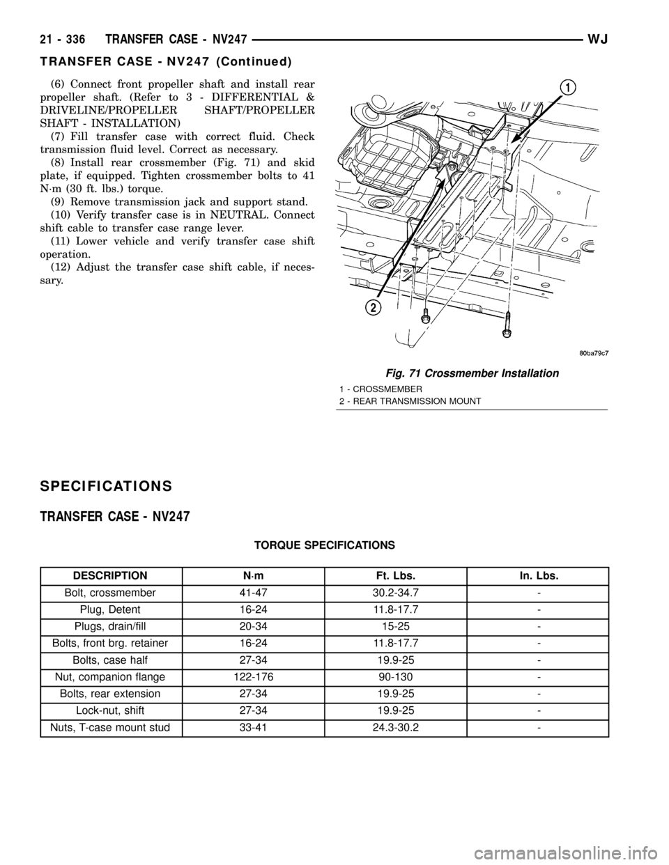
(8) Install rear crossmember (Fig. 71) and skid
plate, if equipped. Tighten crossmember bolts to 41
N´m (30 ft. lbs.) torque.
(9) Remove transmission jack and support stand.
(10) Verify transfer case is in NEUTRAL. Connect
shift cable to transfer case range lever.
(11) Lower vehicle and verify transfer case shift
operation.
(12) Adjust the transfer case shift cable, if neces-
sary.
SPECIFICATIONS
TRANSFER CASE - NV247
TORQUE SPECIFICATIONS
DESCRIPTION N´m Ft. Lbs. In. Lbs.
Bolt, crossmember 41-47 30.2-34.7 -
Plug, Detent 16-24 11.8-17.7 -
Plugs, drain/fill 20-34 15-25 -
Bolts, front brg. retainer 16-24 11.8-17.7 -
Bolts, case half 27-34 19.9-25 -
Nut, companion flange 122-176 90-130 -
Bolts, rear extension 27-34 19.9-25 -
Lock-nut, shift 27-34 19.9-25 -
Nuts, T-case mount stud 33-41 24.3-30.2 -
Fig. 71 Crossmember Installation
1 - CROSSMEMBER
2 - REAR TRANSMISSION MOUNT
21 - 336 TRANSFER CASE - NV247WJ
TRANSFER CASE - NV247 (Continued)
Page 2152 of 2199

REFRIGERANT
DESCRIPTION
The refrigerant used in this air conditioning sys-
tem is a HydroFluoroCarbon (HFC), type R-134a.
Unlike R-12, which is a ChloroFluoroCarbon (CFC),
R-134a refrigerant does not contain ozone-depleting
chlorine. R-134a refrigerant is a non-toxic, non-flam-
mable, clear, and colorless liquefied gas.
Even though R-134a does not contain chlorine, it
must be reclaimed and recycled just like CFC-type
refrigerants. This is because R-134a is a greenhouse
gas and can contribute to global warming.
OPERATION
R-134a refrigerant is not compatible with R-12
refrigerant in an air conditioning system. Even a
small amount of R-12 added to an R-134a refrigerant
system will cause compressor failure, refrigerant oil
sludge or poor air conditioning system performance.
In addition, the PolyAlkylene Glycol (PAG) synthetic
refrigerant oils used in an R-134a refrigerant system
are not compatible with the mineral-based refriger-
ant oils used in an R-12 refrigerant system.
R-134a refrigerant system service ports, service
tool couplers and refrigerant dispensing bottles have
all been designed with unique fittings to ensure that
an R-134a system is not accidentally contaminated
with the wrong refrigerant (R-12). There are also
labels posted in the engine compartment of the vehi-
cle and on the compressor identifying to service tech-
nicians that the air conditioning system is equipped
with R-134a.
REFRIGERANT OIL
DESCRIPTION
The refrigerant oil used in R-134a refrigerant sys-
tems is a synthetic-based, PolyAlkylene Glycol (PAG),
wax-free lubricant. Mineral-based R-12 refrigerant
oils are not compatible with PAG oils, and should
never be introduced to an R-134a refrigerant system.
There are different PAG oils available, and each
contains a different additive package. The 10PA17
compressor used in this vehicle is designed to use an
ND8 PAG refrigerant oil. Use only refrigerant oil of
this same type to service the refrigerant system.
OPERATION
After performing any refrigerant recovery or recy-
cling operation, always replenish the refrigerant sys-
tem with the same amount of the recommended
refrigerant oil as was removed. Too little refrigerant
oil can cause compressor damage, and too much can
reduce air conditioning system performance.PAG refrigerant oil is much more hygroscopic than
mineral oil, and will absorb any moisture it comes
into contact with, even moisture in the air. The PAG
oil container should always be kept tightly capped
until it is ready to be used. After use, recap the oil
container immediately to prevent moisture contami-
nation.
STANDARD PROCEDURE - REFRIGERANT OIL
LEVEL
When an air conditioning system is assembled at
the factory, all components except the compressor are
refrigerant oil free. After the refrigerant system has
been charged and operated, the refrigerant oil in the
compressor is dispersed throughout the refrigerant
system. The accumulator, evaporator, condenser, and
compressor will each retain a significant amount of
the needed refrigerant oil.
It is important to have the correct amount of oil in
the refrigerant system. This ensures proper lubrica-
tion of the compressor. Too little oil will result in
damage to the compressor. Too much oil will reduce
the cooling capacity of the air conditioning system.
It will not be necessary to check the oil level in the
compressor or to add oil, unless there has been an oil
loss. An oil loss may occur due to a rupture or leak
from a refrigerant line, a connector fitting, a compo-
nent, or a component seal. If a leak occurs, add 30
milliliters (1 fluid ounce) of refrigerant oil to the
refrigerant system after the repair has been made.
Refrigerant oil loss will be evident at the leak point
by the presence of a wet, shiny surface around the
leak.
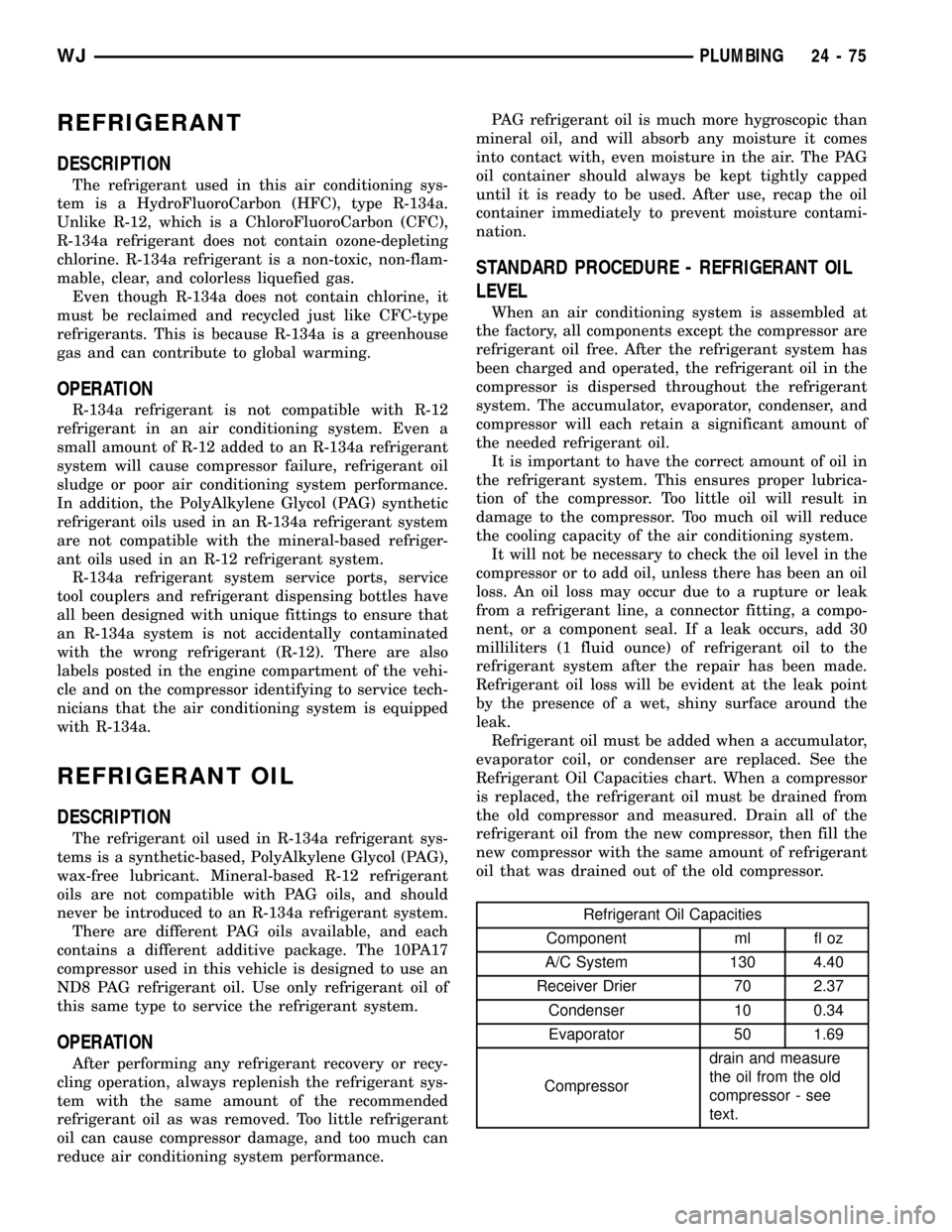
Refrigerant oil must be added when a accumulator,
evaporator coil, or condenser are replaced. See the
Refrigerant Oil Capacities chart. When a compressor
is replaced, the refrigerant oil must be drained from
the old compressor and measured. Drain all of the
refrigerant oil from the new compressor, then fill the
new compressor with the same amount of refrigerant
oil that was drained out of the old compressor.
Refrigerant Oil Capacities
Component ml fl oz
A/C System 130 4.40
Receiver Drier 70 2.37
Condenser 10 0.34
Evaporator 50 1.69
Compressordrain and measure
the oil from the old
compressor - see
text.
WJPLUMBING 24 - 75
Page 2192 of 2199

Check the vapor/vacuum lines at the LDP, LDP
filter and EVAP canister purge solenoid for
damage or leaks. If a leak is present, a Diagnos-
tic Trouble Code (DTC) may be set.
(2) Connect electrical connector to LDP.
(3) While raising front section of support bracket,
connect LDP wiring clip (Fig. 20).
(4) Install 3 LDP mounting bolts (Fig. 19). Refer to
Torque Specifications.
(5) Join front and rear sections of two-piece sup-
port bracket by installing 3 bolts on bottom of sup-
port bracket (Fig. 17). Do not tighten bolts at this
time.
(6) Install support bracket brace bolt (Fig. 17). Do
not tighten bolt at this time.
(7) Tighten 2 support bracket nuts at frame rail
(Fig. 19). Refer to Torque Specifications.
(8) Tighten 3 support bracket bolts and brace bolt.
Refer to Torque Specifications.
(9) Position stone shield behind left/rear wheel
(Fig. 18). Install new plastic rivets.
ORVR
DESCRIPTION
The ORVR (On-Board Refueling Vapor Recovery)
system consists of a unique fuel tank, flow manage-
ment valve, fluid control valve, one-way check valve
and vapor canister. Certain ORVR components can be
found in (Fig. 1).
OPERATION
The ORVR (On-Board Refueling Vapor Recovery)
system is used to remove excess fuel tank vapors.
This is done while the vehicle is being refueled. Cer-
tain ORVR components can be found in (Fig. 1).
Fuel flowing into the fuel filler tube (approx. 1º
I.D.) creates an aspiration effect drawing air into the
fuel fill tube. During refueling, the fuel tank is
vented to the EVAP canister to capture escaping
vapors. With air flowing into the filler tube, there are
no fuel vapors escaping to the atmosphere. Once the
refueling vapors are captured by the EVAP canister,
the vehicle's computer controlled purge system draws
vapor out of the canister for the engine to burn. The
vapor flow is metered by the purge solenoid so that
there is no, or minimal impact on driveability or
tailpipe emissions.As fuel starts to flow through the fuel fill tube, it
opens the normally closed check valve and enters the
fuel tank. Vapor or air is expelled from the tank
through the control valve and on to the vapor canis-
ter. Vapor is absorbed in the EVAP canister until
vapor flow in the lines stops. This stoppage occurs
following fuel shut-off, or by having the fuel level in
the tank rise high enough to close the control valve.
This control valve contains a float that rises to seal
the large diameter vent path to the EVAP canister.
At this point in the refueling process, fuel tank pres-
sure increases, the check valve closes (preventing liq-
uid fuel from spiting back at the operator), and fuel
then rises up the fuel filler tube to shut off the dis-
pensing nozzle.
PCV VALVE
DIAGNOSIS AND TESTING - PCV VALVE/PCV
SYSTEM - 4.7L
(1) Disconnect PCV line/hose (Fig. 21) by discon-
necting rubber connecting hose at PCV valve fitting.
(2) Remove PCV valve at oil filler tube by rotating
PCV valve downward until locating tabs have been
freed at cam lock (Fig. 21). After tabs have cleared,
pull valve straight out from filler tube.To prevent
damage to PCV valve locating tabs, valve must
be pointed downward for removal. Do not force
valve from oil filler tube.
(3) After valve is removed, check condition of valve
o-ring (Fig. 21). Also, PCV valve should rattle when
shaken.
(4) Reconnect PCV valve to its connecting line/
hose.
(5) Start engine and bring to idle speed.
(6) If valve is not plugged, a hissing noise will be
heard as air passes through valve. Also, a strong vac-
uum should be felt with a finger placed at valve
inlet.
(7) If vacuum is not felt at valve inlet, check line/
hose for kinks or for obstruction. If necessary, clean
out intake manifold fitting at rear of manifold. Do
this by turning a 1/4 inch drill (by hand) through the
fitting to dislodge any solid particles. Blow out the
fitting with shop air. If necessary, use a smaller drill
to avoid removing any metal from the fitting.
WJEVAPORATIVE EMISSIONS 25 - 37
LEAK DETECTION PUMP (Continued)