2003 JEEP GRAND CHEROKEE fasteners
[x] Cancel search: fastenersPage 1893 of 2199
DOOR
REMOVAL
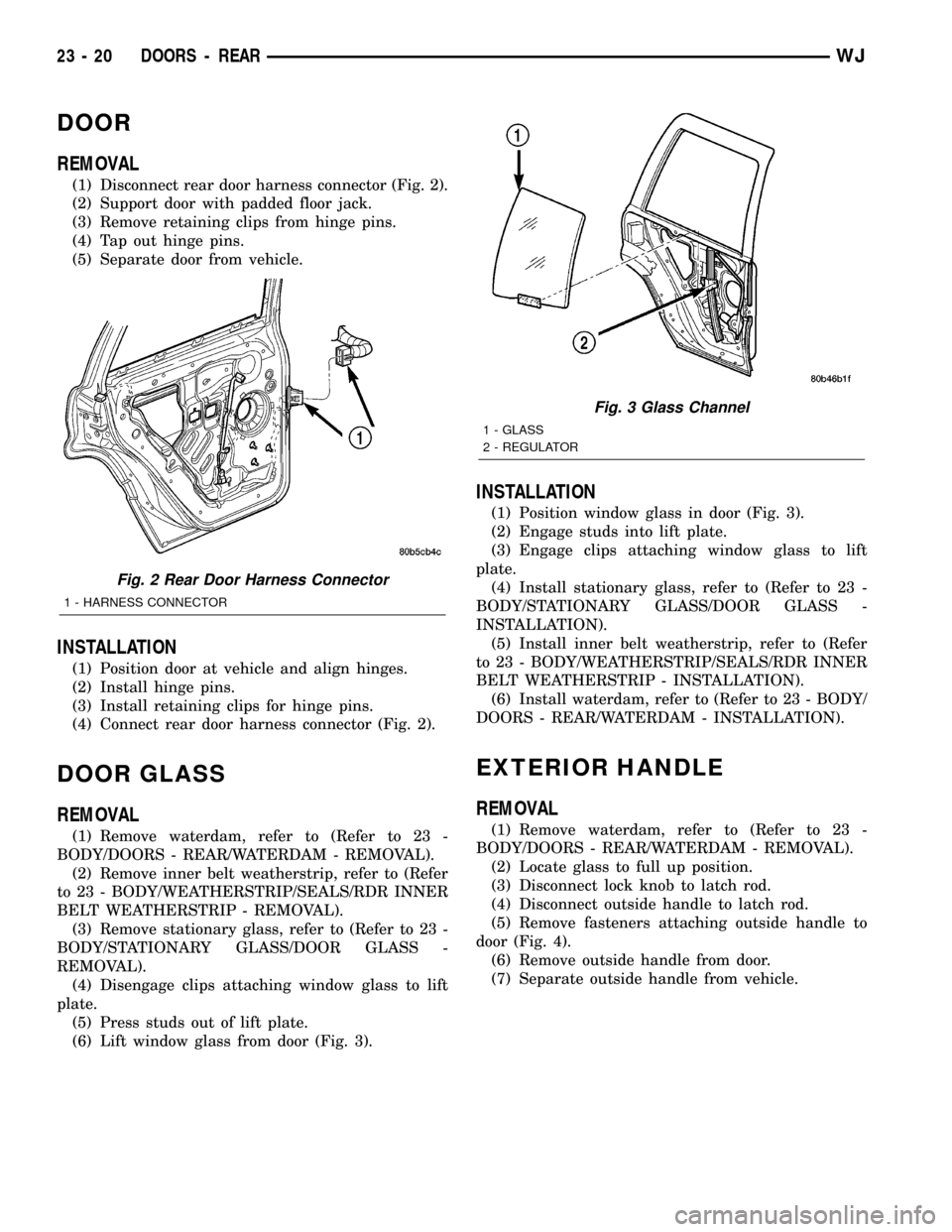
(1) Disconnect rear door harness connector (Fig. 2).
(2) Support door with padded floor jack.
(3) Remove retaining clips from hinge pins.
(4) Tap out hinge pins.
(5) Separate door from vehicle.
INSTALLATION
(1) Position door at vehicle and align hinges.
(2) Install hinge pins.
(3) Install retaining clips for hinge pins.
(4) Connect rear door harness connector (Fig. 2).
DOOR GLASS
REMOVAL
(1) Remove waterdam, refer to (Refer to 23 -
BODY/DOORS - REAR/WATERDAM - REMOVAL).
(2) Remove inner belt weatherstrip, refer to (Refer
to 23 - BODY/WEATHERSTRIP/SEALS/RDR INNER
BELT WEATHERSTRIP - REMOVAL).
(3) Remove stationary glass, refer to (Refer to 23 -
BODY/STATIONARY GLASS/DOOR GLASS -
REMOVAL).
(4) Disengage clips attaching window glass to lift
plate.
(5) Press studs out of lift plate.
(6) Lift window glass from door (Fig. 3).
INSTALLATION
(1) Position window glass in door (Fig. 3).
(2) Engage studs into lift plate.
(3) Engage clips attaching window glass to lift
plate.
(4) Install stationary glass, refer to (Refer to 23 -
BODY/STATIONARY GLASS/DOOR GLASS -
INSTALLATION).
(5) Install inner belt weatherstrip, refer to (Refer
to 23 - BODY/WEATHERSTRIP/SEALS/RDR INNER
BELT WEATHERSTRIP - INSTALLATION).
(6) Install waterdam, refer to (Refer to 23 - BODY/
DOORS - REAR/WATERDAM - INSTALLATION).
EXTERIOR HANDLE
REMOVAL
(1) Remove waterdam, refer to (Refer to 23 -
BODY/DOORS - REAR/WATERDAM - REMOVAL).
(2) Locate glass to full up position.
(3) Disconnect lock knob to latch rod.
(4) Disconnect outside handle to latch rod.
(5) Remove fasteners attaching outside handle to
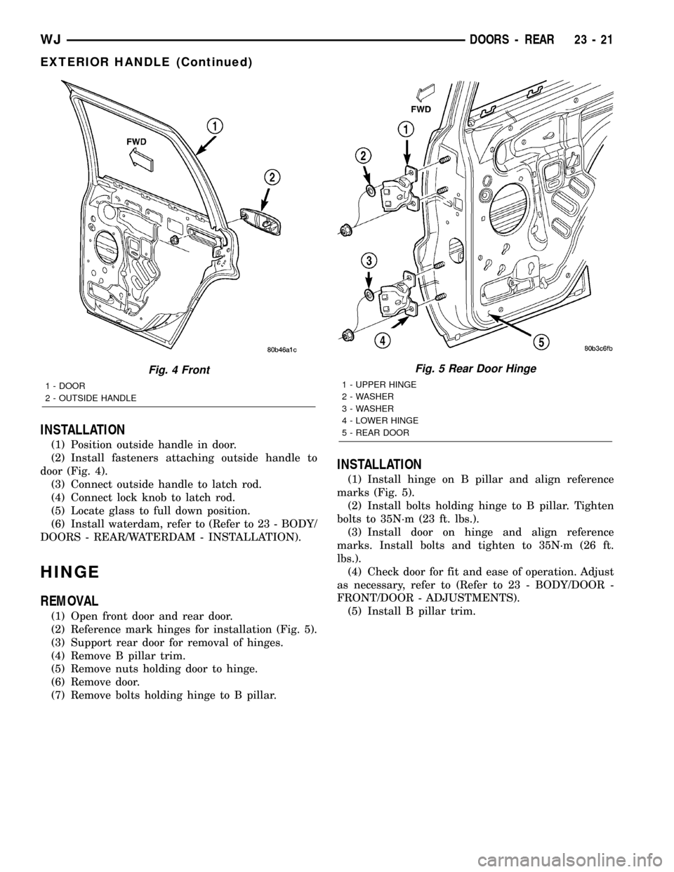
door (Fig. 4).
(6) Remove outside handle from door.
(7) Separate outside handle from vehicle.
Fig. 2 Rear Door Harness Connector
1 - HARNESS CONNECTOR
Fig. 3 Glass Channel
1 - GLASS
2 - REGULATOR
23 - 20 DOORS - REARWJ
Page 1894 of 2199
INSTALLATION
(1) Position outside handle in door.
(2) Install fasteners attaching outside handle to
door (Fig. 4).
(3) Connect outside handle to latch rod.
(4) Connect lock knob to latch rod.
(5) Locate glass to full down position.
(6) Install waterdam, refer to (Refer to 23 - BODY/
DOORS - REAR/WATERDAM - INSTALLATION).
HINGE
REMOVAL
(1) Open front door and rear door.
(2) Reference mark hinges for installation (Fig. 5).
(3) Support rear door for removal of hinges.
(4) Remove B pillar trim.
(5) Remove nuts holding door to hinge.
(6) Remove door.
(7) Remove bolts holding hinge to B pillar.
INSTALLATION
(1) Install hinge on B pillar and align reference
marks (Fig. 5).
(2) Install bolts holding hinge to B pillar. Tighten
bolts to 35N´m (23 ft. lbs.).
(3) Install door on hinge and align reference
marks. Install bolts and tighten to 35N´m (26 ft.
lbs.).
(4) Check door for fit and ease of operation. Adjust
as necessary, refer to (Refer to 23 - BODY/DOOR -
FRONT/DOOR - ADJUSTMENTS).
(5) Install B pillar trim.
Fig. 4 Front
1 - DOOR
2 - OUTSIDE HANDLE
Fig. 5 Rear Door Hinge
1 - UPPER HINGE
2 - WASHER
3 - WASHER
4 - LOWER HINGE
5 - REAR DOOR
WJDOORS - REAR 23 - 21
EXTERIOR HANDLE (Continued)
Page 1896 of 2199
LATCH STRIKER
REMOVAL
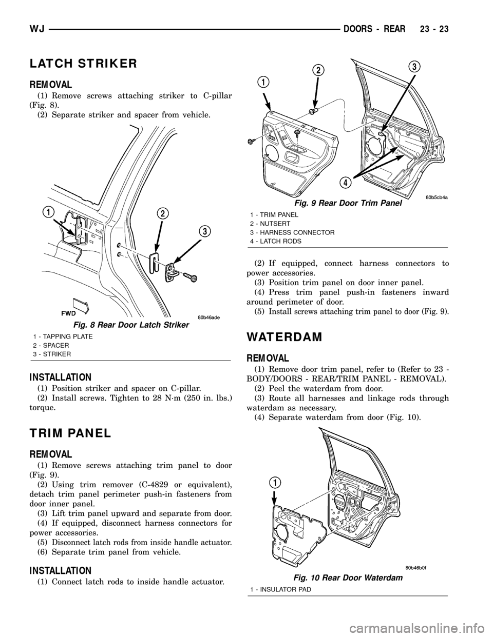
(1) Remove screws attaching striker to C-pillar
(Fig. 8).
(2) Separate striker and spacer from vehicle.
INSTALLATION
(1) Position striker and spacer on C-pillar.
(2) Install screws. Tighten to 28 N´m (250 in. lbs.)
torque.
TRIM PANEL
REMOVAL
(1) Remove screws attaching trim panel to door
(Fig. 9).
(2) Using trim remover (C-4829 or equivalent),
detach trim panel perimeter push-in fasteners from
door inner panel.
(3) Lift trim panel upward and separate from door.
(4) If equipped, disconnect harness connectors for
power accessories.
(5)
Disconnect latch rods from inside handle actuator.
(6) Separate trim panel from vehicle.
INSTALLATION
(1) Connect latch rods to inside handle actuator.(2) If equipped, connect harness connectors to
power accessories.
(3) Position trim panel on door inner panel.
(4) Press trim panel push-in fasteners inward
around perimeter of door.
(5)
Install screws attaching trim panel to door (Fig. 9).
WATERDAM
REMOVAL
(1) Remove door trim panel, refer to (Refer to 23 -
BODY/DOORS - REAR/TRIM PANEL - REMOVAL).
(2) Peel the waterdam from door.
(3) Route all harnesses and linkage rods through
waterdam as necessary.
(4) Separate waterdam from door (Fig. 10).
Fig. 8 Rear Door Latch Striker
1 - TAPPING PLATE
2 - SPACER
3 - STRIKER
Fig. 9 Rear Door Trim Panel
1 - TRIM PANEL
2 - NUTSERT
3 - HARNESS CONNECTOR
4 - LATCH RODS
Fig. 10 Rear Door Waterdam
1 - INSULATOR PAD
WJDOORS - REAR 23 - 23
Page 1897 of 2199
INSTALLATION
(1) Waterdam contact surface must be free of con-
taminants. Clean as necessary.
(2) Route all harnesses and linkage rods through
waterdam as necessary.
(3) Position waterdam on door and align all holes
(Fig. 10).
(4) Press waterdam on door.
(5) Install door trim panel, refer to (Refer to 23 -
BODY/DOORS - REAR/TRIM PANEL - INSTALLA-
TION).
WINDOW REGULATOR
REMOVAL
(1) Remove waterdam, refer to (Refer to 23 -
BODY/DOORS - REAR/WATERDAM - REMOVAL).
(2) Remove the stationary glass, refer to (Refer to
23 - BODY/STATIONARY GLASS/DOOR GLASS -
REMOVAL).
(3) Raise the door glass and support.
(4) Disconnect the speaker harness and power win-
dow harness, if equipped.
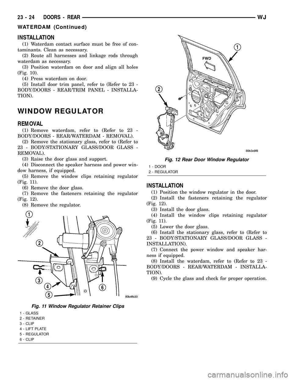
(5) Remove the window clips retaining regulator
(Fig. 11).
(6) Remove the door glass.
(7) Remove the fasteners retaining the regulator
(Fig. 12).
(8) Remove the regulator.
INSTALLATION
(1) Position the window regulator in the door.
(2) Install the fasteners retaining the regulator
(Fig. 12).
(3) Install the door glass.
(4) Install the window clips retaining regulator
(Fig. 11).
(5) Lower the door glass.
(6) Install the stationary glass, refer to (Refer to
23 - BODY/STATIONARY GLASS/DOOR GLASS -
INSTALLATION).
(7) Connect the power window and speaker har-
ness if equipped.
(8) Install the waterdam, refer to (Refer to 23 -
BODY/DOORS - REAR/WATERDAM - INSTALLA-
TION).
(9) Cycle the glass and check for proper operation.
Fig. 11 Window Regulator Retainer Clips
1 - GLASS
2 - RETAINER
3 - CLIP
4 - LIFT PLATE
5 - REGULATOR
6 - CLIP
Fig. 12 Rear Door Window Regulator
1 - DOOR
2 - REGULATOR
23 - 24 DOORS - REARWJ
WATERDAM (Continued)
Page 1907 of 2199

(6) Remove bolts attaching hinges to hood.
(7) With the aid of a helper, remove hood from
vehicle.
INSTALLATION
(1) Position hood on hinges.
(2) Install bolts finger-tight.
(3) Align hinges with installation reference marks
and tighten bolts.
(4) Install hood support prop rods.
(5) Connect underhood lamp connector.
(6) Inspect hood for proper alignment and adjust
as necessary.
ADJUSTMENTS
HOOD ADJUSTMENT
The hood attaching holes are enlarged to aid front,
back and side to side adjustment.
(1) If hood is low in relation to cowl panel, insert
shims between hinge and hood.
(2) Adjust hood bumper in or out to adjust hood-
to-fender height alignment.
(3) Adjust the hood latch as necessary. Tighten the
nuts to 11N´m (8 ft. lbs.).
(4) Align the latch striker so that striker enters
the latch squarely and without binding.
INSULATION
REMOVAL
(1) Raise the hood.
(2) Remove the insulation panel fasteners.
(3) Remove the hood insulation panel.
INSTALLATION
(1) Position the insulation panel on the underside
of the hood.
(2) Install the insulation panel fasteners.
(3) Close the hood.
LATCH
REMOVAL
(1) Remove nuts attaching latch to radiator cross-
member support (Fig. 2).
(2) Disconnect hood release cable from latch.
(3) Separate latch from vehicle.
INSTALLATION
(1) Connect latch release cable to latch.
(2) Position latch on radiator crossmember sup-
port.
(3) Install nuts attaching latch to radiator cross-
member support. Tighten nuts to 11 N´m (8 ft. lbs.)
torque (Fig. 2).
Fig. 2 Hood Latch
1 - HOOD RELEASE CABLE
2-LATCH
3 - BUMPER
23 - 34 HOODWJ
HOOD (Continued)
Page 1908 of 2199
LATCH RELEASE CABLE
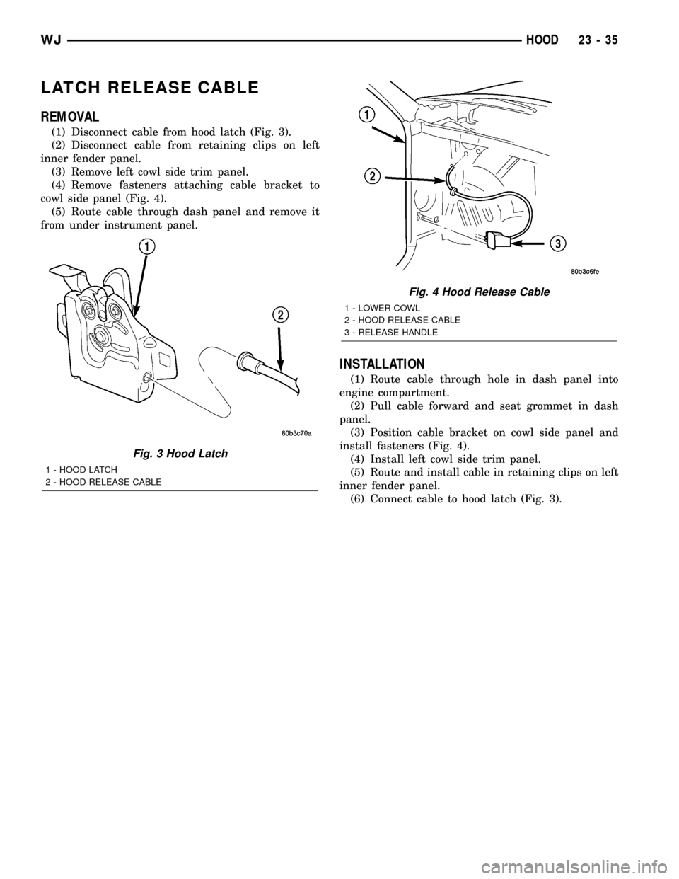
REMOVAL
(1) Disconnect cable from hood latch (Fig. 3).
(2) Disconnect cable from retaining clips on left
inner fender panel.
(3) Remove left cowl side trim panel.
(4) Remove fasteners attaching cable bracket to
cowl side panel (Fig. 4).
(5) Route cable through dash panel and remove it
from under instrument panel.
INSTALLATION
(1) Route cable through hole in dash panel into
engine compartment.
(2) Pull cable forward and seat grommet in dash
panel.
(3) Position cable bracket on cowl side panel and
install fasteners (Fig. 4).
(4) Install left cowl side trim panel.
(5) Route and install cable in retaining clips on left
inner fender panel.
(6) Connect cable to hood latch (Fig. 3).
Fig. 3 Hood Latch
1 - HOOD LATCH
2 - HOOD RELEASE CABLE
Fig. 4 Hood Release Cable
1 - LOWER COWL
2 - HOOD RELEASE CABLE
3 - RELEASE HANDLE
WJHOOD 23 - 35
Page 1963 of 2199
REAR SEAT BACK COVER
REMOVAL
(1) Remove seat back (Refer to 23 - BODY/SEATS/
REAR SEAT BACK - REMOVAL).
(2) Remove head restraint (Refer to 23 - BODY/
SEATS/REAR HEADREST - REMOVAL).
(3) Remove head restraint caps.
(4) Disengage J-straps on outboard side of seat
back.
(5) Disengage J-straps at base of seat back.
(6) Remove screws attaching latch release handle
to seat back frame.
(7) Roll seat back cover upward.
(8) Disengage hook and loop fasteners attaching
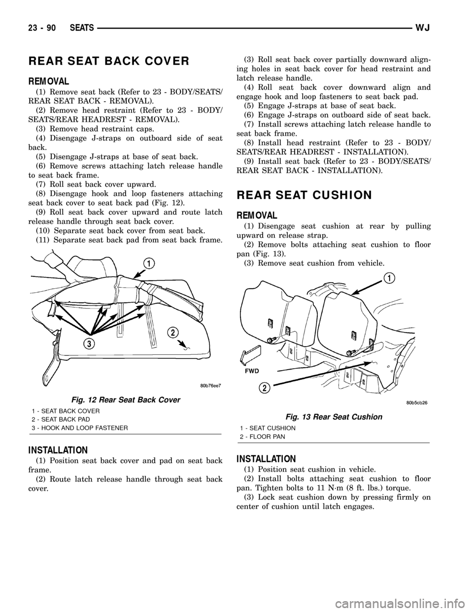
seat back cover to seat back pad (Fig. 12).
(9) Roll seat back cover upward and route latch
release handle through seat back cover.
(10) Separate seat back cover from seat back.
(11) Separate seat back pad from seat back frame.
INSTALLATION
(1) Position seat back cover and pad on seat back
frame.
(2) Route latch release handle through seat back
cover.(3) Roll seat back cover partially downward align-
ing holes in seat back cover for head restraint and
latch release handle.
(4) Roll seat back cover downward align and
engage hook and loop fasteners to seat back pad.
(5) Engage J-straps at base of seat back.
(6) Engage J-straps on outboard side of seat back.
(7) Install screws attaching latch release handle to
seat back frame.
(8) Install head restraint (Refer to 23 - BODY/
SEATS/REAR HEADREST - INSTALLATION).
(9) Install seat back (Refer to 23 - BODY/SEATS/
REAR SEAT BACK - INSTALLATION).
REAR SEAT CUSHION
REMOVAL
(1) Disengage seat cushion at rear by pulling
upward on release strap.
(2) Remove bolts attaching seat cushion to floor
pan (Fig. 13).
(3) Remove seat cushion from vehicle.
INSTALLATION
(1) Position seat cushion in vehicle.
(2) Install bolts attaching seat cushion to floor
pan. Tighten bolts to 11 N´m (8 ft. lbs.) torque.
(3) Lock seat cushion down by pressing firmly on
center of cushion until latch engages.
Fig. 12 Rear Seat Back Cover
1 - SEAT BACK COVER
2 - SEAT BACK PAD
3 - HOOK AND LOOP FASTENERFig. 13 Rear Seat Cushion
1 - SEAT CUSHION
2 - FLOOR PAN
23 - 90 SEATSWJ
Page 1964 of 2199
REAR SEAT CUSHION COVER
REMOVAL
(1) Remove rear seat cushion (Refer to 23 - BODY/
SEATS/REAR SEAT CUSHION - REMOVAL).
(2) From the underside of the seat, disengage
J-straps attaching cover to seat cushion base panel.
(3) Remove push-in fasteners attaching cushion
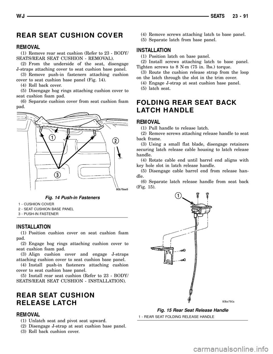
cover to seat cushion base panel (Fig. 14).
(4) Roll back cover.
(5) Disengage hog rings attaching cushion cover to
seat cushion foam pad.
(6) Separate cushion cover from seat cushion foam
pad.
INSTALLATION
(1) Position cushion cover on seat cushion foam
pad.
(2) Engage hog rings attaching cushion cover to
seat cushion foam pad.
(3) Align cushion cover and engage J-straps
attaching cushion cover to seat cushion base panel.
(4) Install push-in fasteners attaching cushion
cover to seat cushion base panel.
(5) Install rear seat cushion (Refer to 23 - BODY/
SEATS/REAR SEAT CUSHION - INSTALLATION).
REAR SEAT CUSHION
RELEASE LATCH
REMOVAL
(1) Unlatch seat and pivot seat upward.
(2) Disengage J-strap at seat cushion base panel.
(3) Roll back cushion cover.(4) Remove screws attaching latch to base panel.
(5) Separate latch from base panel.
INSTALLATION
(1) Position latch on base panel.
(2) Install screws attaching latch to base panel.
Tighten screws to 8 N´m (75 in. lbs.) torque.
(3) Route the cushion release strap from the loop
on the latch through the slot in the trim cover.
(4) Engage J-strap at seat cushion base panel.
(5) latch seat.
FOLDING REAR SEAT BACK
LATCH HANDLE
REMOVAL
(1) Pull handle to release latch.
(2) Remove screws attaching release handle to seat
back frame.
(3) Using a small flat blade, disengage retainers
securing latch release cable housing to latch release
handle.
(4) Rotate cable end until barrel end aligns with
key hole slot in latch release handle.
(5) Disengage cable barrel end from release han-
dle.
(6) Separate latch release handle from seat back
(Fig. 15).
Fig. 14 Push-in Fasteners
1 - CUSHION COVER
2 - SEAT CUSHION BASE PANEL
3 - PUSH-IN FASTENER
Fig. 15 Rear Seat Release Handle
1 - REAR SEAT FOLDING RELEASE HANDLE
WJSEATS 23 - 91