2003 JEEP GRAND CHEROKEE Head lamps
[x] Cancel search: Head lampsPage 611 of 2199

operates the front wipers at the programmed speed
and intervals requested by the RSM to maintain vis-
ibility through the windshield.
²Continuous Wipe Mode- The control knob on
the control stalk of the right (wiper) multi-function
switch has two continuous wipe positions, Low and
High. When selected, these switch positions will
cause the two-speed front wiper motor to operate in a
continuous low or high speed cycle.
²Headlamps On With Wipers- The BCM pro-
vides an automatic headlamps on with wipers feature
for models equipped with the optional automatic
headlamps. This is a customer programmable fea-
ture. If this feature is enabled, the headlamps will
turn on automatically when the windshield wipers
are turned on; and, if the headlamps were turned on
automatically when the wipers were turned on, they
will turn off automatically when the wipers are
turned off. In models equipped with the optional
automatic wiper feature, when the automatic wiper
mode is selected the headlamps will turn on auto-
matically only after the wipers complete three auto-
matic wipe cycles within about thirty seconds, and
they will turn off automatically after three minutes
elapse without any automatic wipe cycles. (Refer to 8
- ELECTRICAL/OVERHEAD CONSOLE - STAN-
DARD PROCEDURE - ELECTRONIC VEHICLE
INFORMATION CENTER PROGRAMMING).
²Mist Wipe Mode- The control stalk of the right
(wiper) multi-function switch has a momentary Mist
position. When selected, this switch position will
operate the front wipers in a low speed continuous
cycle for as long as the switch is held closed, then
will complete the current wipe cycle and park the
front wiper blades near the base of the windshield
when the switch is released.
²Speed Sensitive Intermittent Wipe Mode-
Except on models equipped with the optional auto-
matic wiper system, the internal circuitry of both the
right (wiper) multi-function switch and the BCM
work in concert to provide an intermittent wipe mode
with five delay interval selections. The BCM auto-
matically adjusts each manually selected delay inter-
val to compensate for vehicle speed.
²Washer Mode- When the momentary front
wash position of the control stalk for the right
(wiper) multi-function switch is selected with the
front wiper system operating in a continuous wipe
mode, washer fluid will be dispensed onto the wind-
shield glass through the washer nozzles for as long
as the washer switch is held closed. When the front
washer switch is actuated with the front wiper sys-
tem operating in an intermittent wipe mode, washer
fluid is still dispensed until the switch is released;
however, the front wipers will operate in a low speed
continuous cycle from the time the washer switch isclosed until several wipe cycles after the switch is
released, before returning to the selected intermit-
tent wipe mode.
²Wipe-After-Wash Mode- When the momentary
front wash position of the control stalk for the right
(wiper) multi-function switch is selected with the
front wiper system turned Off, the internal circuitry
of the BCM provides a wipe-after-wash feature.
When selected, this feature will operate the front
washer pump/motor and the front wipers for as long
as the front washer switch is held closed, then pro-
vide several additional wipe cycles after the switch is
released before parking the front wiper blades near
the base of the windshield.
OPERATION
The front wiper and washer system is designed to
provide the vehicle operator with a convenient, safe,
and reliable means of maintaining visibility through
the windshield glass. The various components of this
system are designed to convert electrical energy pro-
duced by the vehicle electrical system into the
mechanical action of the wiper blades to wipe the
outside surface of the glass, as well as into the
hydraulic action of the washer system to apply
washer fluid stored in an on-board reservoir to the
area of the glass to be wiped. When combined, these
components provide the means to effectively main-
tain clear visibility for the vehicle operator by remov-
ing excess accumulations of rain, snow, bugs, mud, or
other minor debris that might be encountered while
driving the vehicle under numerous types of inclem-
ent operating conditions from the outside windshield
glass surface.
The vehicle operator initiates all front wiper and
washer system functions with the control stalk of the
right (wiper) multi-function switch that extends from
the right side of the steering column, just below the
steering wheel. Rotating the control knob on the end
of the right (wiper) multi-function switch control
stalk selects the Off, Delay (on models not equipped
with the optional automatic wiper system), Auto (on
models equipped with the optional automatic wiper
system), Low, or High front wiper system operating
modes. In the Delay mode, the control knob also
allows the vehicle operator to select from one of five
intermittent wipe Delay intervals. In the Auto mode,
the control knob also allows the vehicle operator to
select from one of five automatic wiper sensitivity
levels. Pulling the right control stalk downwards
actuates the momentary front wiper system Mist
mode switch, while pulling the right control stalk
towards the steering wheel actuates the front washer
system switch. The multi-function switch provides
hard wired resistor multiplexed inputs to the Body
Control Module (BCM) for all of the front wiper sys-
8R - 4 FRONT WIPERS/WASHERSWJ
FRONT WIPERS/WASHERS (Continued)
Page 672 of 2199

8W-02 COMPONENT INDEX
Component Page
A/C Compressor Clutch................. 8W-42
A/C Pressure Transducer................ 8W-42
Accelerator Pedal Position Sensor......... 8W-30
Accessory Delay Relay.................. 8W-64
Adjustable Pedals..................... 8W-30
Airbags............................. 8W-43
Ambient Temperature Sensor............ 8W-45
Antennas............................ 8W-47
Ash Receiver Lamp.................... 8W-44
Auto Shut Down Relay................. 8W-30
Automatic Day/Night Mirror............. 8W-49
Automatic Headlamp Light Sensor/VTSS
LED.............................. 8W-39
Automatic Zone Control Module.......... 8W-42
Back-Up Lamp Relay................... 8W-51
Battery Temperature Sensor............. 8W-30
Battery............................. 8W-20
Blend Door Motor/Actuator.............. 8W-42
Blower Motor......................... 8W-42
Body Control Module................... 8W-45
Boost Pressure Sensor.................. 8W-30
Brake Lamp Switch.................... 8W-33
Camshaft Position Sensor............... 8W-30
Capacitors........................... 8W-30
Cargo Lamp.......................... 8W-44
Center High Mounted Stop Lamp......... 8W-51
Cigar Lighter......................... 8W-41
Circuit Breakers...................... 8W-12
Clockspring.................. 8W-33, 41, 43, 47
Coil On Plugs......................... 8W-30
Coil Rail............................. 8W-30
Combination Flasher................... 8W-52
Compact Disc Changer.................. 8W-47
Controller Antilock Brake............... 8W-35
Coolant Level Sensor................... 8W-45
Courtesy Lamps....................... 8W-44
Crankcase Heater..................... 8W-30
Crankshaft Position Sensor.............. 8W-30
Cylinder Lock Switches................. 8W-61
Data Link Connector................... 8W-18
Diagnostic Junction Port................ 8W-18
EGR Solenoid......................... 8W-30
Electric Brake........................ 8W-54
Electronic Speed Control Servo........... 8W-33
Engine Control Module................. 8W-30
Engine Coolant Temperature Sensor...... 8W-30
Engine Oil Pressure Sensor.............. 8W-30
Engine Starter Motor................... 8W-21
EVAP/Purge Solenoid................... 8W-30
Fog Lamps........................ 8W-50, 51
Fuel Injectors......................... 8W-30
Fuel Pressure Sensor................... 8W-30Component Page
Fuel Pressure Solenoid................. 8W-30
Fuel Pump........................... 8W-30
Fuel Tank Module..................... 8W-30
Fuses............................ 8W-10, 12
Fusible Link....................... 8W-10, 20
Grounds............................. 8W-15
Generator......................... 8W-20, 30
Glove Box Lamp...................... 8W-44
Glow Plugs........................... 8W-30
Headlamp Leveling Motor............... 8W-50
Heated Seats......................... 8W-63
High Beam Headlamps................. 8W-50
Hood Ajar Switch...................... 8W-39
Horns............................... 8W-41
Hydraulic Cooling Module............ 8W-30, 42
Idle Air Control Motor.................. 8W-30
Ignition Switch....................... 8W-10
Impact Sensors....................... 8W-43
Input Speed Sensor.................... 8W-31
Instrument Cluster.................... 8W-40
Intake Air Temperature Sensor........... 8W-30
Intake Port Swirl Actuator.............. 8W-30
Intrusion Transceiver Module............ 8W-49
Junction Block........................ 8W-12
Knock Sensor......................... 8W-30
Lamp Assemblies................... 8W-51, 52
Leak Detection Pump.................. 8W-30
License Lamps........................ 8W-51
Liftgate............................. 8W-61
Line Pressure Sensor................... 8W-31
Low Beam Headlamps.................. 8W-50
Low Beam Relay...................... 8W-50
Low Beam/Daytime Running Lamp Relay . . . 8W-50
Lumbar Motor........................ 8W-63
Lumbar Switch....................... 8W-63
Manifold Absolute Pressure Sensor........ 8W-30
Manual Temperature Control............. 8W-42
Mass Air Flow Sensor.................. 8W-30
Memory Set Switch................. 8W-62, 63
Mode Door Motor/Actuator............... 8W-42
Multi-Function Switch............... 8W-50, 53
Output Speed Sensor................... 8W-31
Overhead Map/Courtesy Lamp........... 8W-44
Oxygen Sensors....................... 8W-30
Park Brake Switch..................... 8W-40
Park Lamp........................... 8W-50
Park/Neutral Position Switch............ 8W-31
Park/Turn Signal Lamps................ 8W-50
Power Amplifier....................... 8W-47
Power Connector...................... 8W-41
Power Distribution Center............... 8W-10
Power Mirrors........................ 8W-62
WJ8W-02 COMPONENT INDEX 8W - 02 - 1
Page 1056 of 2199
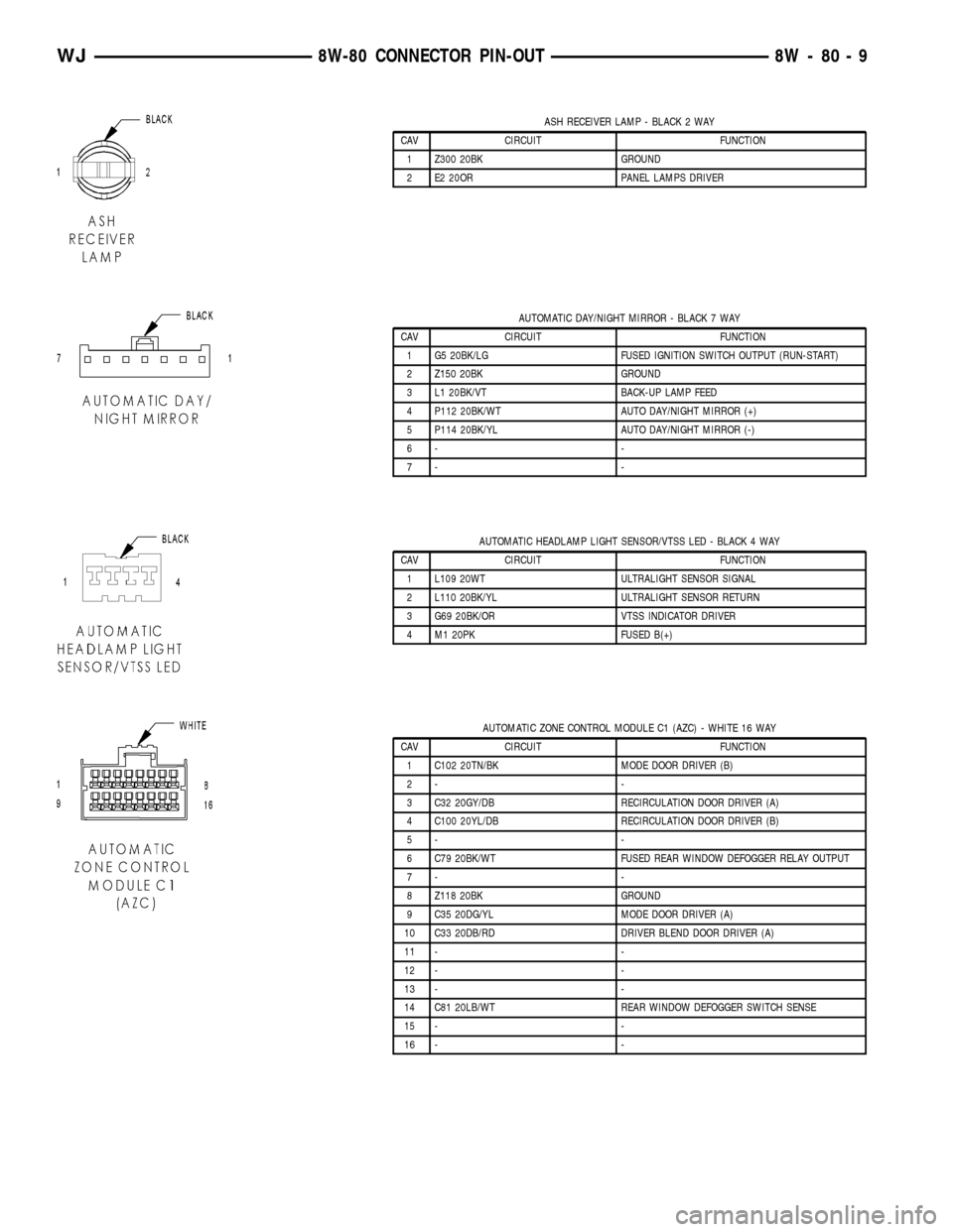
ASH RECEIVER LAMP - BLACK 2 WAY
CAV CIRCUIT FUNCTION
1 Z300 20BK GROUND
2 E2 20OR PANEL LAMPS DRIVER
AUTOMATIC DAY/NIGHT MIRROR - BLACK 7 WAY
CAV CIRCUIT FUNCTION
1 G5 20BK/LG FUSED IGNITION SWITCH OUTPUT (RUN-START)
2 Z150 20BK GROUND
3 L1 20BK/VT BACK-UP LAMP FEED
4 P112 20BK/WT AUTO DAY/NIGHT MIRROR (+)
5 P114 20BK/YL AUTO DAY/NIGHT MIRROR (-)
6- -
7- -
AUTOMATIC HEADLAMP LIGHT SENSOR/VTSS LED - BLACK 4 WAY
CAV CIRCUIT FUNCTION
1 L109 20WT ULTRALIGHT SENSOR SIGNAL
2 L110 20BK/YL ULTRALIGHT SENSOR RETURN
3 G69 20BK/OR VTSS INDICATOR DRIVER
4 M1 20PK FUSED B(+)
AUTOMATIC ZONE CONTROL MODULE C1 (AZC) - WHITE 16 WAY
CAV CIRCUIT FUNCTION
1 C102 20TN/BK MODE DOOR DRIVER (B)
2- -
3 C32 20GY/DB RECIRCULATION DOOR DRIVER (A)
4 C100 20YL/DB RECIRCULATION DOOR DRIVER (B)
5- -
6 C79 20BK/WT FUSED REAR WINDOW DEFOGGER RELAY OUTPUT
7- -
8 Z118 20BK GROUND
9 C35 20DG/YL MODE DOOR DRIVER (A)
10 C33 20DB/RD DRIVER BLEND DOOR DRIVER (A)
11 - -
12 - -
13 - -
14 C81 20LB/WT REAR WINDOW DEFOGGER SWITCH SENSE
15 - -
16 - -
WJ8W-80 CONNECTOR PIN-OUT 8W - 80 - 9
Page 1058 of 2199
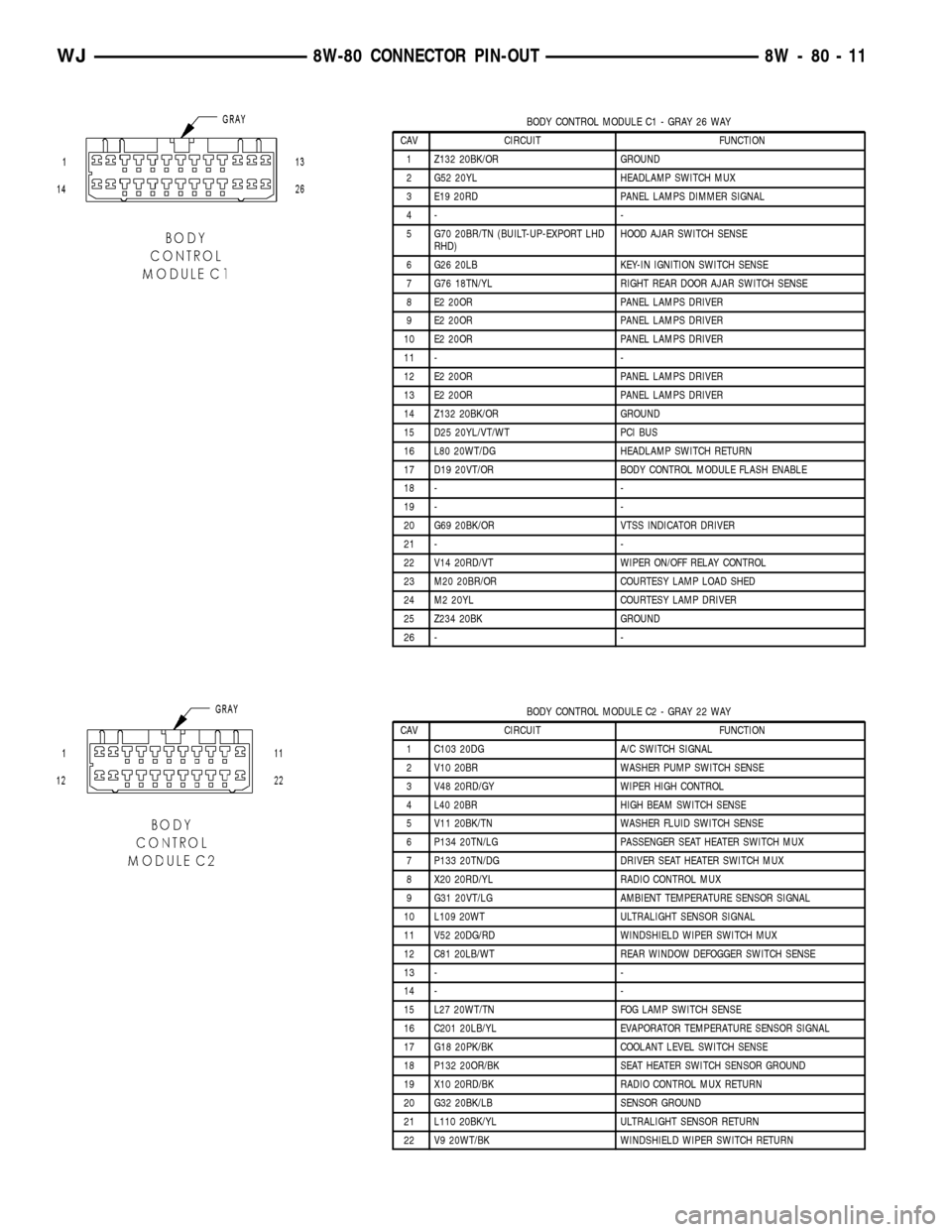
BODY CONTROL MODULE C1 - GRAY 26 WAY
CAV CIRCUIT FUNCTION
1 Z132 20BK/OR GROUND
2 G52 20YL HEADLAMP SWITCH MUX
3 E19 20RD PANEL LAMPS DIMMER SIGNAL
4- -
5 G70 20BR/TN (BUILT-UP-EXPORT LHD
RHD)HOOD AJAR SWITCH SENSE
6 G26 20LB KEY-IN IGNITION SWITCH SENSE
7 G76 18TN/YL RIGHT REAR DOOR AJAR SWITCH SENSE
8 E2 20OR PANEL LAMPS DRIVER
9 E2 20OR PANEL LAMPS DRIVER
10 E2 20OR PANEL LAMPS DRIVER
11 - -
12 E2 20OR PANEL LAMPS DRIVER
13 E2 20OR PANEL LAMPS DRIVER
14 Z132 20BK/OR GROUND
15 D25 20YL/VT/WT PCI BUS
16 L80 20WT/DG HEADLAMP SWITCH RETURN
17 D19 20VT/OR BODY CONTROL MODULE FLASH ENABLE
18 - -
19 - -
20 G69 20BK/OR VTSS INDICATOR DRIVER
21 - -
22 V14 20RD/VT WIPER ON/OFF RELAY CONTROL
23 M20 20BR/OR COURTESY LAMP LOAD SHED
24 M2 20YL COURTESY LAMP DRIVER
25 Z234 20BK GROUND
26 - -
BODY CONTROL MODULE C2 - GRAY 22 WAY
CAV CIRCUIT FUNCTION
1 C103 20DG A/C SWITCH SIGNAL
2 V10 20BR WASHER PUMP SWITCH SENSE
3 V48 20RD/GY WIPER HIGH CONTROL
4 L40 20BR HIGH BEAM SWITCH SENSE
5 V11 20BK/TN WASHER FLUID SWITCH SENSE
6 P134 20TN/LG PASSENGER SEAT HEATER SWITCH MUX
7 P133 20TN/DG DRIVER SEAT HEATER SWITCH MUX
8 X20 20RD/YL RADIO CONTROL MUX
9 G31 20VT/LG AMBIENT TEMPERATURE SENSOR SIGNAL
10 L109 20WT ULTRALIGHT SENSOR SIGNAL
11 V52 20DG/RD WINDSHIELD WIPER SWITCH MUX
12 C81 20LB/WT REAR WINDOW DEFOGGER SWITCH SENSE
13 - -
14 - -
15 L27 20WT/TN FOG LAMP SWITCH SENSE
16 C201 20LB/YL EVAPORATOR TEMPERATURE SENSOR SIGNAL
17 G18 20PK/BK COOLANT LEVEL SWITCH SENSE
18 P132 20OR/BK SEAT HEATER SWITCH SENSOR GROUND
19 X10 20RD/BK RADIO CONTROL MUX RETURN
20 G32 20BK/LB SENSOR GROUND
21 L110 20BK/YL ULTRALIGHT SENSOR RETURN
22 V9 20WT/BK WINDSHIELD WIPER SWITCH RETURN
WJ8W-80 CONNECTOR PIN-OUT 8W - 80 - 11
Page 1142 of 2199
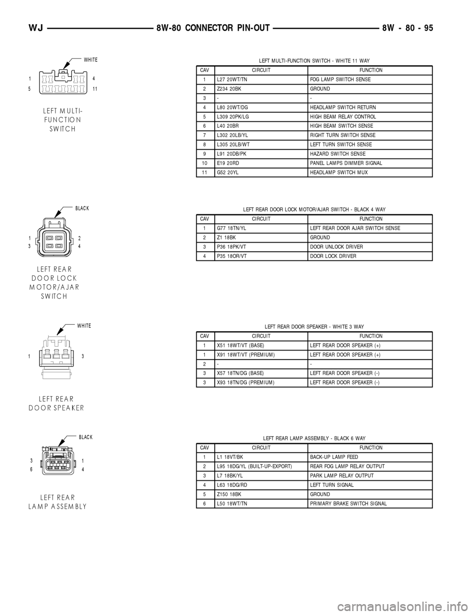
LEFT MULTI-FUNCTION SWITCH - WHITE 11 WAY
CAV CIRCUIT FUNCTION
1 L27 20WT/TN FOG LAMP SWITCH SENSE
2 Z234 20BK GROUND
3- -
4 L80 20WT/DG HEADLAMP SWITCH RETURN
5 L309 20PK/LG HIGH BEAM RELAY CONTROL
6 L40 20BR HIGH BEAM SWITCH SENSE
7 L302 20LB/YL RIGHT TURN SWITCH SENSE
8 L305 20LB/WT LEFT TURN SWITCH SENSE
9 L91 20DB/PK HAZARD SWITCH SENSE
10 E19 20RD PANEL LAMPS DIMMER SIGNAL
11 G52 20YL HEADLAMP SWITCH MUX
LEFT REAR DOOR LOCK MOTOR/AJAR SWITCH - BLACK 4 WAY
CAV CIRCUIT FUNCTION
1 G77 18TN/YL LEFT REAR DOOR AJAR SWITCH SENSE
2 Z1 18BK GROUND
3 P36 18PK/VT DOOR UNLOCK DRIVER
4 P35 18OR/VT DOOR LOCK DRIVER
LEFT REAR DOOR SPEAKER - WHITE 3 WAY
CAV CIRCUIT FUNCTION
1 X51 18WT/VT (BASE) LEFT REAR DOOR SPEAKER (+)
1 X91 18WT/VT (PREMIUM) LEFT REAR DOOR SPEAKER (+)
2- -
3 X57 18TN/DG (BASE) LEFT REAR DOOR SPEAKER (-)
3 X93 18TN/DG (PREMIUM) LEFT REAR DOOR SPEAKER (-)
LEFT REAR LAMP ASSEMBLY - BLACK 6 WAY
CAV CIRCUIT FUNCTION
1 L1 18VT/BK BACK-UP LAMP FEED
2 L95 18DG/YL (BUILT-UP-EXPORT) REAR FOG LAMP RELAY OUTPUT
3 L7 18BK/YL PARK LAMP RELAY OUTPUT
4 L63 18DG/RD LEFT TURN SIGNAL
5 Z150 18BK GROUND
6 L50 18WT/TN PRIMARY BRAKE SWITCH SIGNAL
WJ8W-80 CONNECTOR PIN-OUT 8W - 80 - 95
Page 1261 of 2199
DESCRIPTION N´m Ft. In.
Lbs. Lbs.
Transmission Support Bracket
ÐBolt (Manual) 46 34 Ð
Transmission Support Bracket/
CushionÐBolt (4WD Auto) 75 55 Ð
Transmission Support Adaptor
BracketÐBolts (2WD Auto) 75 55 Ð
Exhaust Manifold/PipeÐNuts 27 20 Ð
Intake/Exhaust Manifold
Fasteners #1-5 33 24 Ð
Fasteners #6 and 7 14 Ð 126
Fasteners #8-11 33 24 Ð
Flywheel to Converter
HousingÐBolts38 28 Ð
Flywheel to CrankshaftÐBolts 143 105 Ð
Front Cover to BlockÐBolts
1/4-20 7 Ð 60
5/16-18 22 Ð 192
Fuel RailÐBolts/Stud 12 Ð 108
GeneratorÐBolts 57 42 Ð
Generator Bracket to EngineÐ
Bolts47 35 Ð
Idler Pulley to Cylinder
HeadÐBolt47 35 Ð
Main Bearing CapÐBolts 108 80 Ð
Oil Filter 18 Ð 156
Oil Filter Connector to
Adaptor 47 35 Ð
Block 68 50 Ð
Adaptor Bolts 102 50 Ð
Oil GalleyÐPlug 41 30 Ð
Oil PanÐBolts
1/4-20 9.5 Ð 84
5/16-18 15 Ð 132
Oil PanÐDrain Plug 34 25 Ð
Oil Pump
Mounting Bolts 23 Ð 204
Cover Bolts 8 Ð 70
Rocker Arm Assembly to
Cylinder
HeadÐCapscrews 30 21 Ð
Spark Plugs 37 27 ÐDESCRIPTION N´m Ft. In.
Lbs. Lbs.
Starter MotorÐMounting Bolts 45 33 Ð
Thermostat HousingÐBolts 18 Ð 156
Throttle BodyÐBolts 10 Ð 90
Vibration DamperÐBolt 108 80 Ð
Water Pump to BlockÐBolts 23 17 Ð
AIR CLEANER ELEMENT
REMOVAL - 4.0L
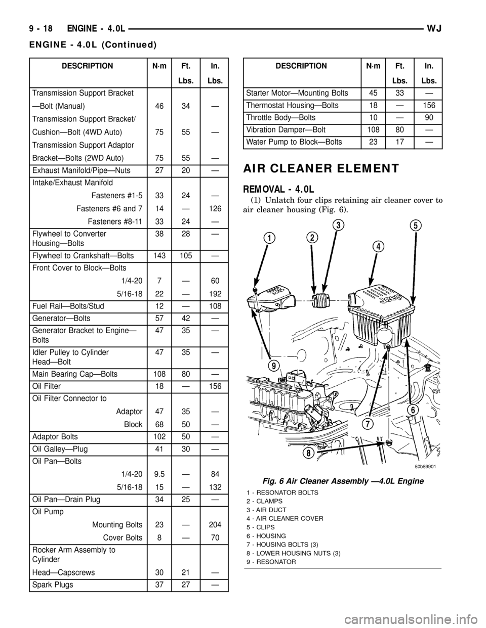
(1) Unlatch four clips retaining air cleaner cover to
air cleaner housing (Fig. 6).
Fig. 6 Air Cleaner Assembly Ð4.0L Engine
1 - RESONATOR BOLTS
2 - CLAMPS
3 - AIR DUCT
4 - AIR CLEANER COVER
5 - CLIPS
6 - HOUSING
7 - HOUSING BOLTS (3)
8 - LOWER HOUSING NUTS (3)
9 - RESONATOR
9 - 18 ENGINE - 4.0LWJ
ENGINE - 4.0L (Continued)
Page 1327 of 2199

AIR CLEANER HOUSING
REMOVAL - 4.7L
(1) Disconnect air cleaner cover-to-air duct clamp
(Fig. 8).
(2) Disconnect air duct at housing.
(3)Each of the 3 air cleaner housing mount-
ing bolts is attached with 2 nuts (an upper nut
and lower nut). DO NOT REMOVE BOLTS. To
prevent stripping bolts, only remove lower
nuts. The lower housing nuts are located under
left front inner fender (Fig. 8).
(a) To gain access to lower nuts, raise vehicle.
(b) Remove clips retaining rubber inner fender
shield.
(c) Pry back shield enough to gain access to
lower nuts.
(d) Remove 3 nuts.(e) Remove air cleaner assembly from vehicle.
(4) If resonator is to be removed, disconnect
breather tube at resonator, disconnect air duct clamp
at resonator (Fig. 8)and remove 2 resonator mount-
ing bolts (at sides of resonator). Remove resonator
from throttle body by loosening clamp at throttle
body.
INSTALLATION - 4.7L
(1) Position air cleaner assembly to body and
install 3 nuts. Tighten nuts to 10 N´m (93 in. lbs.)
torque.To prevent excessive vibration transmit-
ted through housing, the nuts must be properly
torqued. Do not overtighten nuts.
(2) If resonator was removed: Install resonator and
bolts. Tighten bolts to 4 N´m (35 in. lbs.) torque.
Tighten clamp at throttle body to 4 N´m (35 in. lbs.)
torque.
(3) Position fender liner and install clips.
(4) Connect air duct at housing (Fig. 8).
(5) Tighten air duct clamp.
CYLINDER HEAD - LEFT
DESCRIPTION
DESCRIPTION - CYLINDER HEAD
The cylinder heads are made of an aluminum alloy.
The cylinder head features two valves per cylinder
with pressed in powdered metal valve guides. The
cylinder heads also provide enclosures for the timing
chain drain, necessitating unique left and right cylin-
der heads.
DESCRIPTION - VALVE GUIDES
The valve guides are made of powered metal and
are pressed into the cylinder head. The guides are
not replaceable or serviceable, and valve guide ream-
ing is not recommended. If the guides are worn
beyond acceptable limits, replace the cylinder heads.
DIAGNOSIS AND TESTING
DIAGNOSIS AND TESTING - HYDRAULIC LASH
ADJUSTER
A tappet-like noise may be produced from several
items. Check the following items.
(1) Engine oil level too high or too low. This may
cause aerated oil to enter the adjusters and cause
them to be spongy.
(2) Insufficient running time after rebuilding cylin-
der head. Low speed running up to 1 hour may be
required.
Fig. 8 Air Cleaner Assembly - 4.7L
1 - AIR DUCT
2 - CLAMPS
3 - AIR CLEANER COVER
4 - CLIPS
5 - HOUSING
6 - HOUSING BOLTS (3)
7 - LOWER HOUSING NUTS (3)
8 - RESONATOR BOLTS
9 - RESONATOR
9 - 84 ENGINE - 4.7LWJ
AIR CLEANER ELEMENT (Continued)
Page 1400 of 2199
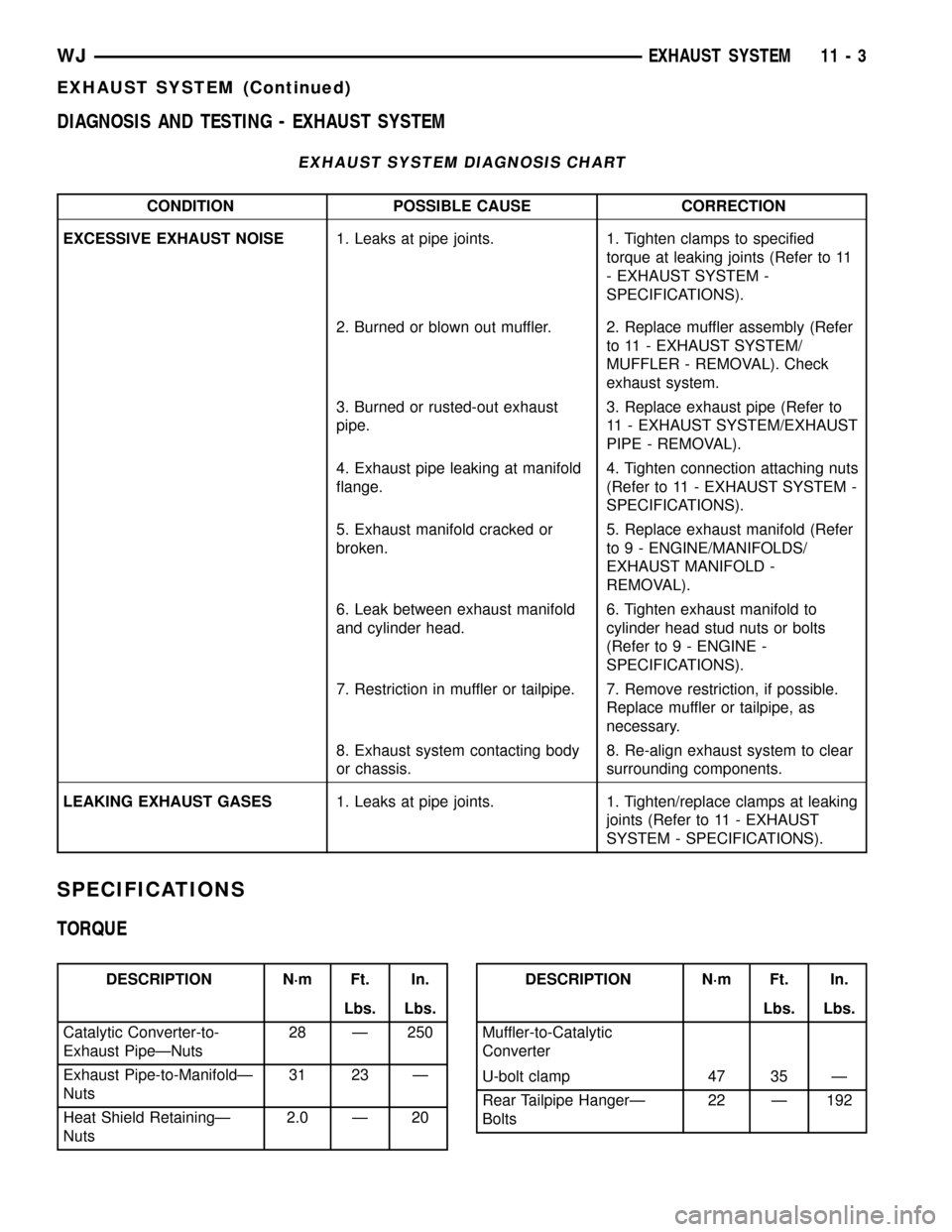
DIAGNOSIS AND TESTING - EXHAUST SYSTEM
EXHAUST SYSTEM DIAGNOSIS CHART
CONDITION POSSIBLE CAUSE CORRECTION
EXCESSIVE EXHAUST NOISE1. Leaks at pipe joints. 1. Tighten clamps to specified
torque at leaking joints (Refer to 11
- EXHAUST SYSTEM -
SPECIFICATIONS).
2. Burned or blown out muffler. 2. Replace muffler assembly (Refer
to 11 - EXHAUST SYSTEM/
MUFFLER - REMOVAL). Check
exhaust system.
3. Burned or rusted-out exhaust
pipe.3. Replace exhaust pipe (Refer to
11 - EXHAUST SYSTEM/EXHAUST
PIPE - REMOVAL).
4. Exhaust pipe leaking at manifold
flange.4. Tighten connection attaching nuts
(Refer to 11 - EXHAUST SYSTEM -
SPECIFICATIONS).
5. Exhaust manifold cracked or
broken.5. Replace exhaust manifold (Refer
to 9 - ENGINE/MANIFOLDS/
EXHAUST MANIFOLD -
REMOVAL).
6. Leak between exhaust manifold
and cylinder head.6. Tighten exhaust manifold to
cylinder head stud nuts or bolts
(Refer to 9 - ENGINE -
SPECIFICATIONS).
7. Restriction in muffler or tailpipe. 7. Remove restriction, if possible.
Replace muffler or tailpipe, as
necessary.
8. Exhaust system contacting body
or chassis.8. Re-align exhaust system to clear
surrounding components.
LEAKING EXHAUST GASES1. Leaks at pipe joints. 1. Tighten/replace clamps at leaking
joints (Refer to 11 - EXHAUST
SYSTEM - SPECIFICATIONS).
SPECIFICATIONS
TORQUE
DESCRIPTION N´m Ft. In.
Lbs. Lbs.
Catalytic Converter-to-
Exhaust PipeÐNuts28 Ð 250
Exhaust Pipe-to-ManifoldÐ
Nuts31 23 Ð
Heat Shield RetainingÐ
Nuts2.0 Ð 20DESCRIPTION N´m Ft. In.
Lbs. Lbs.
Muffler-to-Catalytic
Converter
U-bolt clamp 47 35 Ð
Rear Tailpipe HangerÐ
Bolts22 Ð 192
WJEXHAUST SYSTEM 11 - 3
EXHAUST SYSTEM (Continued)