Page 215 of 2199

(3) Install lower shoe to shoe spring/adjuster
spring. Needle nose pliers can be used to connect
spring to each shoe.
(4) Install the upper shoe to shoe spring/return
spring with brake pliers (Fig. 83).
(5) Install rotor and caliper anchor assembly.
(6) Install anchor bolts and tighten to 90-115 N´m
(66-85 ft. lbs.).
(7) Actuate park brake lever to unlock the park
brake system.
(8) Adjust the parking brake shoes (Fig. 82).
(9) Install wheel and tire assembly.
(10) Lower vehicle and verify correct parking
brake operation.
ADJUSTMENTS - PARKING BRAKE SHOE
(1) Remove wheel and tire assemblies.
(2) Secure rotor with two wheel nuts.
(3) Remove rubber access plug from back of splash
shield.
(4) Insert brake tool through access hole in splash
shield (Fig. 86). Position tool at bottom of star wheel.
(5) Rotate star wheel upward direction to expand
shoes (while facing front of vehicle).
(6) Expand shoes until light drag is experienced.
Then back off adjuster screw only enough to elimi-
nate drag.
(7) Install plug in splash shield access hole.
(8) Install wheel and tire assemblies.
Fig. 83 Lower Spring
1 - REAR SHOE
2 - NEEDLENOSE PLIERS
3 - ADJUSTER SCREW
4 - LOWER SPRING
Fig. 84 Upper Spring
1 - BRAKE PLIERS
2 - REAR SHOE
3 - UPPER SPRING
Fig. 85 Hold-Down Clip And Pin
1 - HOLD-DOWN CLIP
2 - HOLD-DOWN PIN
Fig. 86 Park Brake Shoe Adjustment
1 - ACCESS HOLE
2 - BRAKE ADJUSTING TOOL
3 - SPLASH SHIELD
5 - 40 BRAKES - BASEWJ
SHOES (Continued)
Page 1577 of 2199
Remover, Seal - C-3985-B
Installer, Seal - C-3995-A
Handle, Universal - C-4171
Installer, Seal - C-4193-A
Dial Caliper - C-4962
Kit, Bushing Remover/Installer - C-3887-J
Nut, Bushing Remover - SP-1191, From kit C-3887-J
Cup, Bushing Remover - SP-3633, From kit C-3887-J
Remover, Bushing - SP-3551
Installer, Bushing - SP-5117
21 - 58 AUTOMATIC TRANSMISSION - 42REWJ
AUTOMATIC TRANSMISSION - 42RE (Continued)
Page 1621 of 2199

NOTE: The reaction plate is thinner than the pres-
sure plate in a 42RE transmission.
(5) Install first clutch disc followed by first clutch
plate. Then install remaining clutch discs and plates
in same order.
(6) Install clutch pack pressure plate.
(7) Install clutch pack wire-type retaining ring
(Fig. 182).
INTERMEDIATE SHAFT SPACER SELECTION
(1) Place overdrive unit in vertical position. Mount
it on blocks, or in workbench with appropriate size
mounting hole cut into it. Be sure unit is facing
upward for access to direct clutch hub. Also be sure
output shaft is not loaded and internal components
are moved rearward for accurate measurement.
(2) Determine correct thickness intermediate shaft
spacer as follows:
(a) Insert Special Tool 6312 through sun gear,
planetary gear and into pilot bushing in output
shaft. Be sure tool bottoms against planetary
shoulder.
(b) Position Gauge Tool 6311 across face of over-
drive case (Fig. 183). Then position Dial Caliper
C-4962 over gauge tool.
(c) Extend sliding scale of dial caliper downward
through gauge tool slot until scale contacts end of
Gauge Alignment Tool 6312. Lock scale in place.
Remove dial caliper tool and note distance mea-
sured (Fig. 183).
(d) Select proper thickness end play spacer from
spacer chart based on distance measured (Fig.
184).
(e) Remove Gauge Alignment Tool 6312.
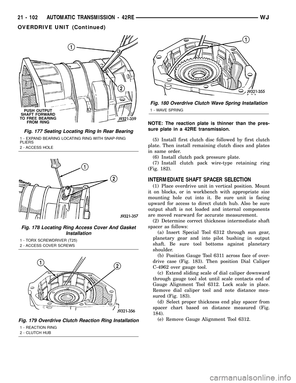
Fig. 177 Seating Locating Ring In Rear Bearing
1 - EXPAND BEARING LOCATING RING WITH SNAP-RING
PLIERS
2 - ACCESS HOLE
Fig. 178 Locating Ring Access Cover And Gasket
Installation
1 - TORX SCREWDRIVER (T25)
2 - ACCESS COVER SCREWS
Fig. 179 Overdrive Clutch Reaction Ring Installation
1 - REACTION RING
2 - CLUTCH HUB
Fig. 180 Overdrive Clutch Wave Spring Installation
1 - WAVE SPRING
21 - 102 AUTOMATIC TRANSMISSION - 42REWJ
OVERDRIVE UNIT (Continued)
Page 1622 of 2199

OD THRUST PLATE SELECTION
(1) Place overdrive unit in vertical position. Mount
it on blocks, or in workbench with appropriate size
mounting hole cut into it. Be sure unit is facing
upward for access to direct clutch hub. Also be sure
output shaft is not loaded and internal components
are moved rearward for accurate measurement.
(2) Determine correct thickness overdrive piston
thrust plate as follows:(a) Position Gauge Tool 6311 across face of over-
drive case. Then position Dial Caliper C-4962 over
gauge tool (Fig. 185).
(b) Measure distance to clutch hub thrust bear-
ing seat at four points 90É apart. Then average
measurements by adding them and dividing by 4.
(c) Select and install required thrust plate from
information in thrust plate chart (Fig. 186).
Fig. 181 42RE Overdrive Clutch Components
1 - REACTION PLATE 2 - PRESSURE PLATE
Fig. 182 Overdrive Clutch Pack Retaining Ring
Installation
1 - OVERDRIVE CLUTCH PACK RETAINING RING
Fig. 183 Shaft End Play Measurement
1 - SPECIAL TOOL 6312
2 - SPECIAL TOOL 6311
3 - SPECIAL TOOL C-4962
WJAUTOMATIC TRANSMISSION - 42RE 21 - 103
OVERDRIVE UNIT (Continued)
Page 1870 of 2199

²Bent or dented
²Leak air through welds
²Have damaged bolt holes
Wheel repairs employing hammering, heating, or
welding are not allowed.
Original equipment wheels are available through
your dealer. Replacement wheels from any other
source should be equivalent in:
²Load carrying capacity
²Diameter
²Width²Offset
²Mounting configuration
Failure to use equivalent replacement wheels may
affect the safety and handling of your vehicle.
Replacement withusedwheels is not recommended.
Their service history may have included severe treat-
ment.
SPECIFICATIONS
TORQUE CHART
TORQUE SPECIFICATIONS
DESCRIPTION N´m Ft. Lbs. In. Lbs.
Lug Nut
1/2 X 20 with 60É Cone115-150 85-115 Ð
STUDS
REMOVAL
CAUTION: Do not use a hammer to remove wheel
studs.
(1) Raise and support vehicle.
(2) Remove wheel and tire assembly.
(3) Remove brake caliper, caliper adapter and
rotor,(Refer to 5 - BRAKES/HYDRAULIC/MECHAN-
ICAL/ROTORS - REMOVAL).
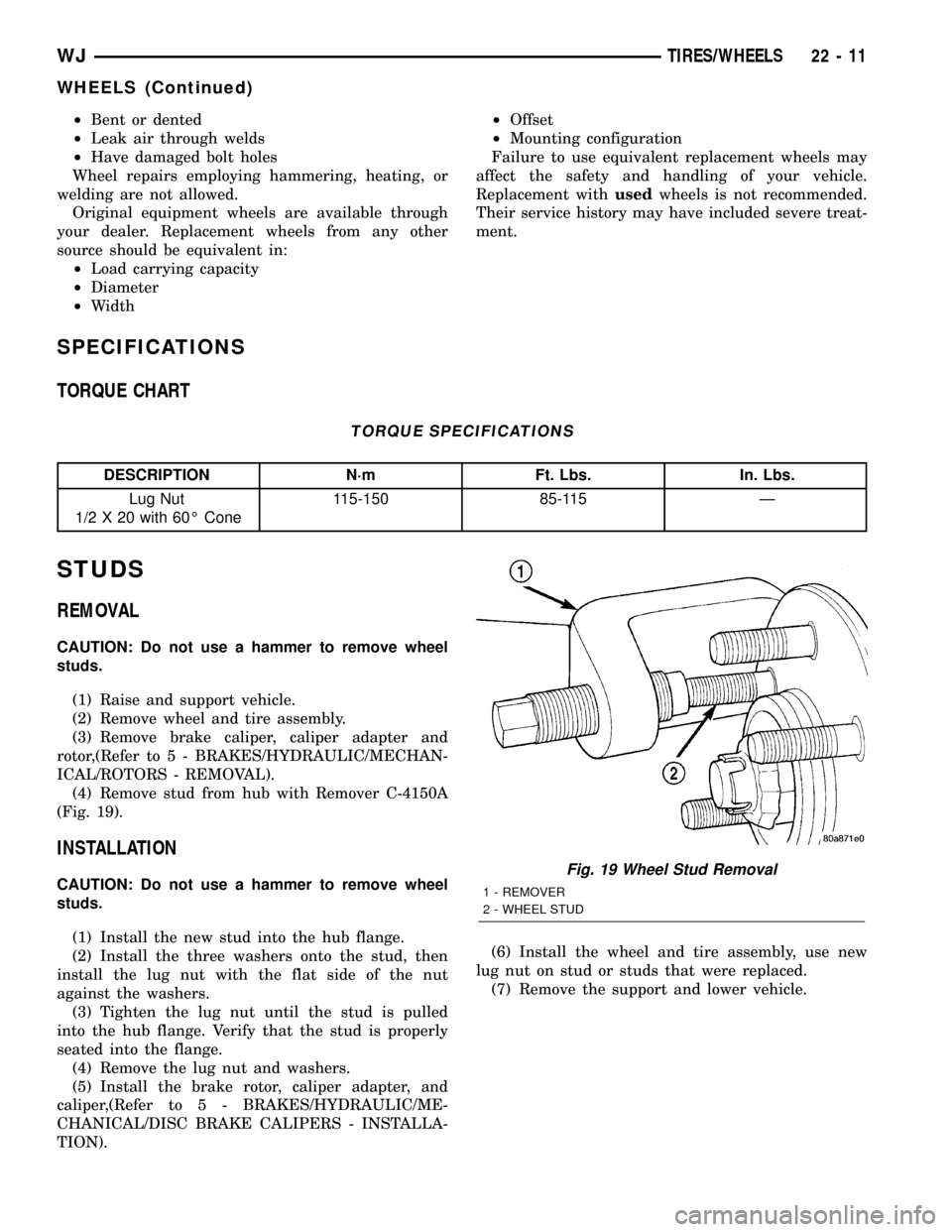
(4) Remove stud from hub with Remover C-4150A
(Fig. 19).
INSTALLATION
CAUTION: Do not use a hammer to remove wheel
studs.
(1) Install the new stud into the hub flange.
(2) Install the three washers onto the stud, then
install the lug nut with the flat side of the nut
against the washers.
(3) Tighten the lug nut until the stud is pulled
into the hub flange. Verify that the stud is properly
seated into the flange.
(4) Remove the lug nut and washers.
(5) Install the brake rotor, caliper adapter, and
caliper,(Refer to 5 - BRAKES/HYDRAULIC/ME-
CHANICAL/DISC BRAKE CALIPERS - INSTALLA-
TION).(6) Install the wheel and tire assembly, use new
lug nut on stud or studs that were replaced.
(7) Remove the support and lower vehicle.Fig. 19 Wheel Stud Removal
1 - REMOVER
2 - WHEEL STUD
WJTIRES/WHEELS 22 - 11
WHEELS (Continued)