2003 JEEP GRAND CHEROKEE Air cleaner
[x] Cancel search: Air cleanerPage 1468 of 2199

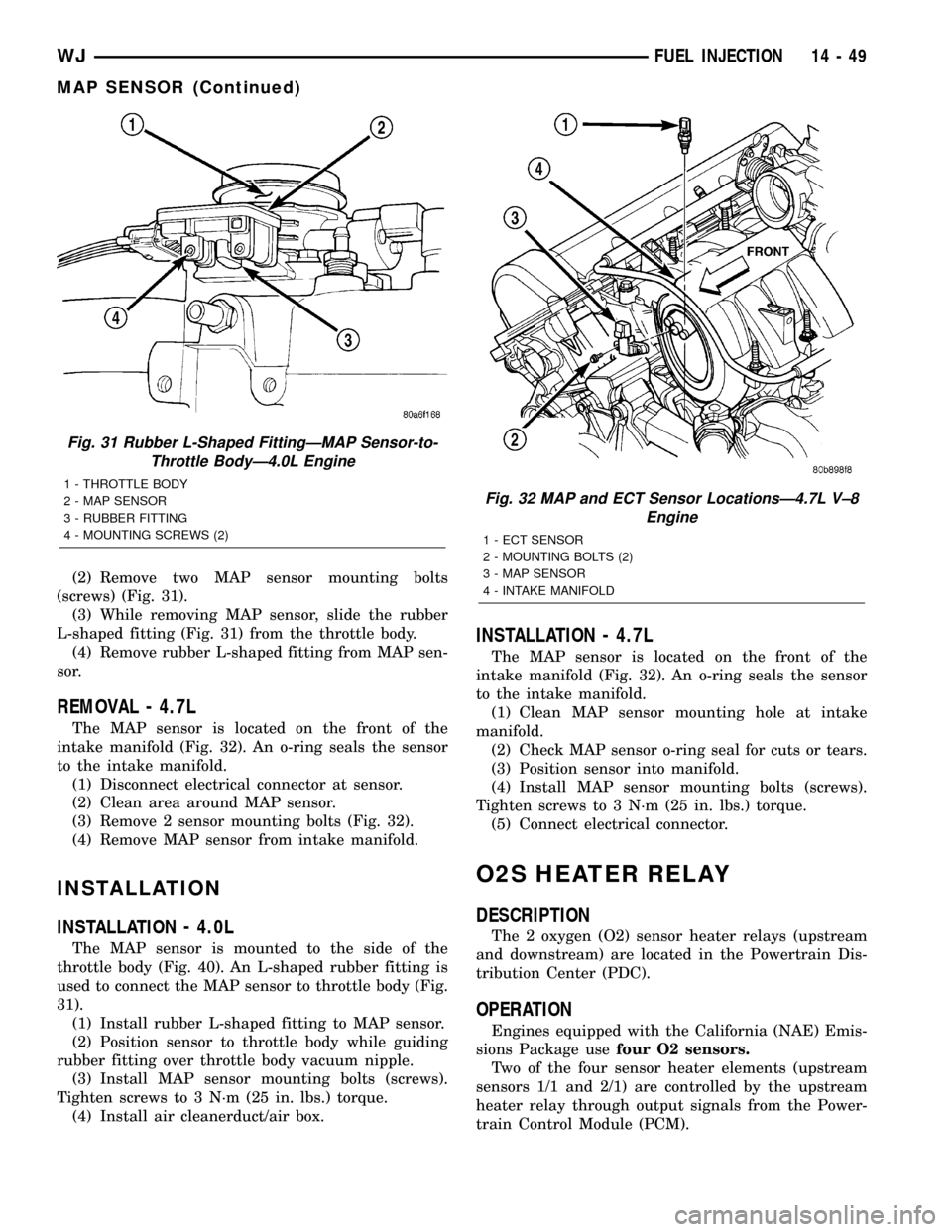
(2) Remove two MAP sensor mounting bolts
(screws) (Fig. 31).
(3) While removing MAP sensor, slide the rubber
L-shaped fitting (Fig. 31) from the throttle body.
(4) Remove rubber L-shaped fitting from MAP sen-
sor.
REMOVAL - 4.7L
The MAP sensor is located on the front of the
intake manifold (Fig. 32). An o-ring seals the sensor
to the intake manifold.
(1) Disconnect electrical connector at sensor.
(2) Clean area around MAP sensor.
(3) Remove 2 sensor mounting bolts (Fig. 32).
(4) Remove MAP sensor from intake manifold.
INSTALLATION
INSTALLATION - 4.0L
The MAP sensor is mounted to the side of the
throttle body (Fig. 40). An L-shaped rubber fitting is
used to connect the MAP sensor to throttle body (Fig.
31).
(1) Install rubber L-shaped fitting to MAP sensor.
(2) Position sensor to throttle body while guiding
rubber fitting over throttle body vacuum nipple.
(3) Install MAP sensor mounting bolts (screws).
Tighten screws to 3 N´m (25 in. lbs.) torque.
(4) Install air cleanerduct/air box.
INSTALLATION - 4.7L
The MAP sensor is located on the front of the
intake manifold (Fig. 32). An o-ring seals the sensor
to the intake manifold.
(1) Clean MAP sensor mounting hole at intake
manifold.
(2) Check MAP sensor o-ring seal for cuts or tears.
(3) Position sensor into manifold.
(4) Install MAP sensor mounting bolts (screws).
Tighten screws to 3 N´m (25 in. lbs.) torque.
(5) Connect electrical connector.
O2S HEATER RELAY
DESCRIPTION
The 2 oxygen (O2) sensor heater relays (upstream
and downstream) are located in the Powertrain Dis-
tribution Center (PDC).
OPERATION
Engines equipped with the California (NAE) Emis-
sions Package usefour O2 sensors.
Two of the four sensor heater elements (upstream
sensors 1/1 and 2/1) are controlled by the upstream
heater relay through output signals from the Power-
train Control Module (PCM).
Fig. 31 Rubber L-Shaped FittingÐMAP Sensor-to-
Throttle BodyÐ4.0L Engine
1 - THROTTLE BODY
2 - MAP SENSOR
3 - RUBBER FITTING
4 - MOUNTING SCREWS (2)Fig. 32 MAP and ECT Sensor LocationsÐ4.7L V±8
Engine
1 - ECT SENSOR
2 - MOUNTING BOLTS (2)
3 - MAP SENSOR
4 - INTAKE MANIFOLD
WJFUEL INJECTION 14 - 49
MAP SENSOR (Continued)
Page 1471 of 2199

THROTTLE BODY
DESCRIPTION
The throttle body is located on the intake manifold.
Fuel does not enter the intake manifold through the
throttle body. Fuel is sprayed into the manifold by
the fuel injectors.
OPERATION
Filtered air from the air cleaner enters the intake
manifold through the throttle body. The throttle body
contains an air control passage controlled by an Idle
Air Control (IAC) motor. The air control passage is
used to supply air for idle conditions. A throttle valve
(plate) is used to supply air for above idle conditions.
Certain sensors are attached to the throttle body.
The accelerator pedal cable, speed control cable and
transmission control cable (when equipped) are con-
nected to the throttle body linkage arm.A (factory adjusted) set screw is used to mechani-
cally limit the position of the throttle body throttle
plate.Never attempt to adjust the engine idle
speed using this screw.All idle speed functions are
controlled by the PCM.
REMOVAL
REMOVAL - 4.0L
A (factory adjusted) set screw is used to mechani-
cally limit the position of the throttle body throttle
plate.Never attempt to adjust the engine idle
speed using this screw.All idle speed functions are
controlled by the Powertrain Control Module (PCM).
(1) Remove air cleaner duct and air resonator box
at throttle body.
(2) Disconnect throttle body electrical connectors
at MAP sensor, IAC motor and TPS (Fig. 35).
Fig. 33 Oxygen Sensor LocationsÐ4.0L Engine
14 - 52 FUEL INJECTIONWJ
O2S SENSOR (Continued)
Page 1493 of 2199

GEAR
TABLE OF CONTENTS
page page
GEAR
DESCRIPTION.........................16
OPERATION...........................16
REMOVAL.............................16
INSTALLATION.........................16
ADJUSTMENTS
STEERING GEAR.....................18
SPECIFICATIONS
POWER STEERING GEAR..............18
SPECIAL TOOLS
POWER STEERING GEAR..............19
PITMAN SHAFT
REMOVAL.............................20INSTALLATION.........................20
PITMAN SHAFT BEARING
REMOVAL.............................22
INSTALLATION.........................22
PITMAN SHAFT SEAL
REMOVAL.............................22
INSTALLATION.........................23
RACK PISTON/VALVE ASSEMBLY
REMOVAL.............................23
INSTALLATION.........................25
STUB SHAFT HOUSING
REMOVAL.............................25
INSTALLATION.........................25
GEAR
DESCRIPTION
The power steering gear is a recirculating ball type
gear (Fig. 1) .
The following gear components can be serviced:
²Pitman Shaft and Cover
²Pitman Shaft Bearings
²Pitman Shaft Oil Seal/Dust Seal
²Stud Shaft Housing with Seal
²O-Rings and Teflon Rings
NOTE: If rack piston assembly is damaged the gear
must be replaced.
OPERATION
The gear acts as a rolling thread between the
worm shaft and rack piston. The worm shaft is sup-
ported by a thrust bearing at the lower end and a
bearing assembly at the upper end. When the worm
shaft is turned the rack piston moves. The rack pis-
ton teeth mesh with the pitman shaft. Turning the
worm shaft turns the pitman shaft, which turns the
steering linkage.
REMOVAL
(1) Place the front wheels in the straight ahead
position with the steering wheel centered and locked.
(2) Remove the air cleaner housing,(Refer to 9 -
ENGINE/AIR INTAKE SYSTEM/AIR CLEANER
HOUSING - REMOVAL).
(3) Drain or siphon the power steering system.(4) Remove the pressure and return lines (Fig.
2)from the steering gear. Refer to hose removal in
this section.
(5) Remove the column coupler shaft bolt (Fig.
2)and remove the shaft from the gear.
(6) Raise and support the vehicle.
(7) Remove the left front wheel and tire assembly.
(8) Remove the pitman arm from gear with Puller
C-4150A.
(9) Remove the windshield washer reservoir,(Refer
to 8 - ELECTRICAL/WIPERS/WASHERS/WASHER
RESERVOIR - REMOVAL).
(10) Remove the steering gear mounting bolts.
Remove the steering gear out of the engine compart-
ment (Fig. 3).
INSTALLATION
(1) Position the steering gear on the frame rail and
install the bolts. Tighten the bolts to 108 N´m (80 ft.
lbs.) torque.
(2) Install the pitman arm and tighten nut to 251
N´m (185 ft. lbs.).
(3) Install windshield washer reservoir,(Refer to 8 -
ELECTRICAL/WIPERS/WASHERS/WASHER RES-
ERVOIR - INSTALLATION).
(4) Install the wheel and tire assembly.
(5) Remove the support and lower the vehicle.
(6) Install the pressure and return hoses to the
steering gear and tighten to 20-38 N´m (14-28 ft.
lbs.).
(7) Install the column coupler shaft.
(8) Install the air cleaner housing,(Refer to 9 -
ENGINE/AIR INTAKE SYSTEM/AIR CLEANER
HOUSING - INSTALLATION).
19 - 16 GEARWJ
Page 1514 of 2199

INSTALLATION
(1) Position and install the power steering cooler
to the vehicle.
(2) Install the three mounting bracket bolts (Fig.
6).
(3) Reconnect the upper hose at cooler (Fig. 6).
(4) Reconnect the lower hose at cooler (Fig. 6).
(5) Connect negative battery cable to battery.
(6) Refill the power steering fluid and bleed the
system,(Refer to 19 - STEERING/PUMP - STAN-
DARD PROCEDURE).
(7) Start engine and check for leaks.
(8) Install the grille opening reinforcement panel
(9) Install the front fascia grille,(Refer to 13 -
FRAMES & BUMPERS/BUMPERS/FRONT FASCIA
- INSTALLATION).
HOSES - 4.0L
DESCRIPTION
DESCRIPTION - PRESSURE LINE
The hose consists of two metal ends and rubber
center section that contains a tuning cable. The
pump end uses a quick connect fitting. Lubircation
must be used on the quick connect nut and o-ring
when installing.
DESCRIPTION - RETURN LINE
Power steering return line is a hose which is
clamped at the pump and the gear.
OPERATION
OPERATION - PRESSURE LINE
Power steering pressure line, is used to transfer
high pressure power steering fluid, from the power
steering pump to the power steering gear on the
4.0L. The 4.7L power steering pressure line, is used
to transfer high pressure power steering fluid, from
the power steering pump to the engine cooling fan
and the steering gear.
OPERATION - RETURN LINE
Power steering return line, is used to transfer low
pressure power steering fluid, from the power steer-
ing gear to the power steering pump.
REMOVAL
(1) Drain the power steering fluid from the reser-
voir.
(2) Remove the air box,(Refer to 9 - ENGINE/AIR
INTAKE SYSTEM/AIR CLEANER HOUSING -
REMOVAL).
(3) Disconnect the power steering pressure hose
from the power steering pump and then the power
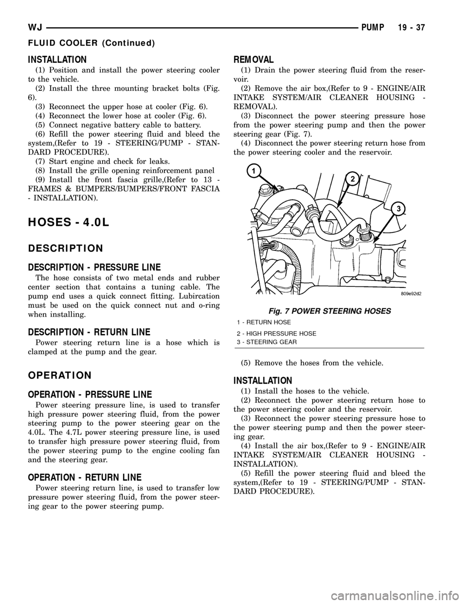
steering gear (Fig. 7).
(4) Disconnect the power steering return hose from
the power steering cooler and the reservoir.
(5) Remove the hoses from the vehicle.
INSTALLATION
(1) Install the hoses to the vehicle.
(2) Reconnect the power steering return hose to
the power steering cooler and the reservoir.
(3) Reconnect the power steering pressure hose to
the power steering pump and then the power steer-
ing gear.
(4) Install the air box,(Refer to 9 - ENGINE/AIR
INTAKE SYSTEM/AIR CLEANER HOUSING -
INSTALLATION).
(5) Refill the power steering fluid and bleed the
system,(Refer to 19 - STEERING/PUMP - STAN-
DARD PROCEDURE).
Fig. 7 POWER STEERING HOSES
1 - RETURN HOSE
2 - HIGH PRESSURE HOSE
3 - STEERING GEAR
WJPUMP 19 - 37
FLUID COOLER (Continued)
Page 1516 of 2199

OPERATION - 3/8º PRESSURE HOSE
High pressure power steering fluid is transmitted
from the hydraulic fan motor to the steering gear by
the 3/8º steering line.
OPERATION - 3/8º GEAR OUTLET HOSE
The gear outlet hose transmits power steering fluid
under moderate low pressure to the power steering
cooler inlet tube.
OPERATION - 3/8ºRETURN HOSE
Low pressure power steering fluid is transmitted
from the steering cooler back to the power steering
pump by the 3/8º return hose.
REMOVAL
REMOVAL - 1/2(PRESSURE HOSE
(1)Drain the power steering fluid from the reservoir.
(2) Remove the air box,(Refer to 9 - ENGINE/AIR
INTAKE SYSTEM/AIR CLEANER HOUSING -
REMOVAL).
(3) Raise and support the vehicle.
(4) Remove the metal skid plate.
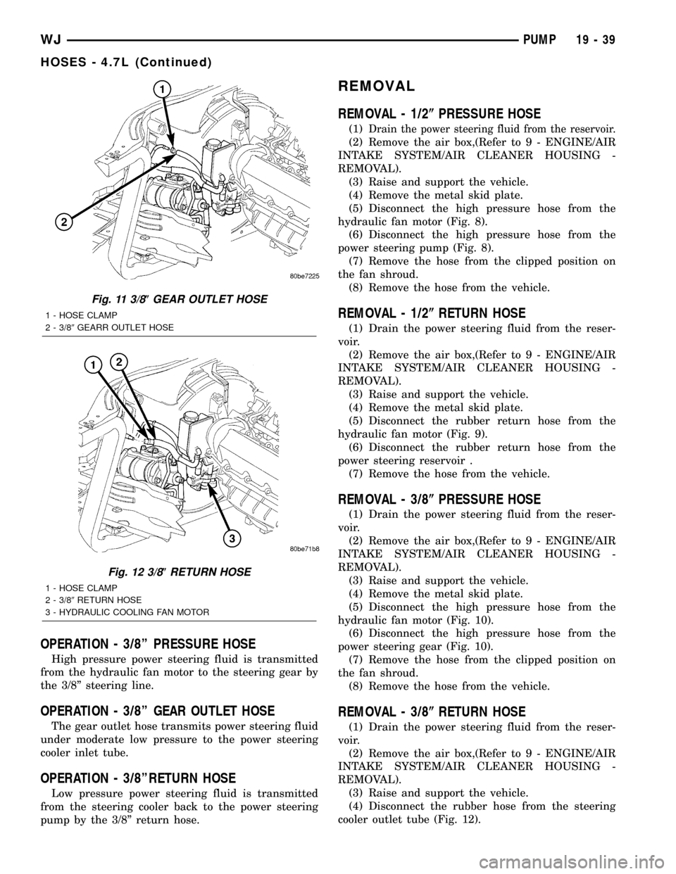
(5) Disconnect the high pressure hose from the
hydraulic fan motor (Fig. 8).
(6) Disconnect the high pressure hose from the
power steering pump (Fig. 8).
(7) Remove the hose from the clipped position on
the fan shroud.
(8) Remove the hose from the vehicle.
REMOVAL - 1/2(RETURN HOSE
(1) Drain the power steering fluid from the reser-
voir.
(2) Remove the air box,(Refer to 9 - ENGINE/AIR
INTAKE SYSTEM/AIR CLEANER HOUSING -
REMOVAL).
(3) Raise and support the vehicle.
(4) Remove the metal skid plate.
(5) Disconnect the rubber return hose from the
hydraulic fan motor (Fig. 9).
(6) Disconnect the rubber return hose from the
power steering reservoir .
(7) Remove the hose from the vehicle.
REMOVAL - 3/8(PRESSURE HOSE
(1) Drain the power steering fluid from the reser-
voir.
(2) Remove the air box,(Refer to 9 - ENGINE/AIR
INTAKE SYSTEM/AIR CLEANER HOUSING -
REMOVAL).
(3) Raise and support the vehicle.
(4) Remove the metal skid plate.
(5) Disconnect the high pressure hose from the
hydraulic fan motor (Fig. 10).
(6) Disconnect the high pressure hose from the
power steering gear (Fig. 10).
(7) Remove the hose from the clipped position on
the fan shroud.
(8) Remove the hose from the vehicle.
REMOVAL - 3/8(RETURN HOSE
(1) Drain the power steering fluid from the reser-
voir.
(2) Remove the air box,(Refer to 9 - ENGINE/AIR
INTAKE SYSTEM/AIR CLEANER HOUSING -
REMOVAL).
(3) Raise and support the vehicle.
(4) Disconnect the rubber hose from the steering
cooler outlet tube (Fig. 12).
Fig. 11 3/8(GEAR OUTLET HOSE
1 - HOSE CLAMP
2 - 3/89GEARR OUTLET HOSE
Fig. 12 3/8(RETURN HOSE
1 - HOSE CLAMP
2 - 3/89RETURN HOSE
3 - HYDRAULIC COOLING FAN MOTOR
WJPUMP 19 - 39
HOSES - 4.7L (Continued)
Page 1517 of 2199

(5) Disconnect the rubber hose from the power
steering reservoir (Fig. 12).
(6) Remove the hose from the vehicle.
REMOVAL - 3/8(GEAR OUTLET HOSE
(1) Drain the power steering fluid from the reser-
voir.
(2) Remove the air box,(Refer to 9 - ENGINE/AIR
INTAKE SYSTEM/AIR CLEANER HOUSING -
REMOVAL).
(3) Raise and support the vehicle.
(4) Disconnect the rubber hose from the steering
cooler inlet tube (Fig. 11).
(5) Disconnect the metal tube from the power
steering gear (Fig. 11).
(6) Remove the hose from the vehicle.
REMOVAL - INLET COOLER HOSE
(1) Disconnect negative battery cable at battery.
(2) Drain the power steering fluid out of the reser-
voir.
(3) Remove the air box,(Refer to 9 - ENGINE/AIR
INTAKE SYSTEM/AIR CLEANER HOUSING -
REMOVAL).
(4) Remove the front fascia grille assembly,(Refer
to 13 - FRAMES & BUMPERS/BUMPERS/FRONT
FASCIA - REMOVAL).
(5) Remove the grille opening reinforcement panel
(6) Place a drain pan under the cooler.
(7) Disconnect the lower hose at cooler (Fig. 6).
(8) Disconnect the cooler hose at the gear.
(9) Remove the bracket holding the cooler hoses
(Fig. 13).
(10) Remove the cooler hose from the vehicle.
REMOVAL - OUTLET COOLER HOSE
(1) Disconnect negative battery cable at battery.
(2) Drain the power steering fluid out of the reser-
voir.
(3) Remove the air box,(Refer to 9 - ENGINE/AIR
INTAKE SYSTEM/AIR CLEANER HOUSING -
REMOVAL).
(4) Remove the front fascia grille assembly,(Refer
to 13 - FRAMES & BUMPERS/BUMPERS/FRONT
FASCIA - REMOVAL).
(5) Remove the grille opening reinforcement panel
(6) Place a drain pan under the cooler.
(7) Disconnect the upper hose at cooler (Fig. 6).
(8) Disconnect the cooler hose at the reservoir.
(9) Remove the bracket holding the cooler hoses
(Fig. 13).
(10) Remove the cooler hose from the vehicle.
INSTALLATION
INSTALLATION - 1/2(PRESSURE HOSE
NOTE: Lubrication and a new o-ring must be used
when reinstalling.
(1) Install the hoses to the vehicle.
(2) Reconnect the high pressure hose to the power
steering pump (Fig. 8) Tighten the hose to 22.5 N´m
(17 ft.lbs.).
(3) Reconnect the high pressure hose to the
hydraulic fan motor (Fig. 8) Tighten the hose to 22.5
N´m (17 ft.lbs.).
(4) Install the hose to the clipped position on the
fan shroud.
(5) Install the metal skid plate.
(6) Install the air box,(Refer to 9 - ENGINE/AIR
INTAKE SYSTEM/AIR CLEANER HOUSING -
INSTALLATION).
(7) Refill the power steering fluid and bleed the
system,(Refer to 19 - STEERING/PUMP - STAN-
DARD PROCEDURE).
INSTALLATION - 1/2(RETURN HOSE
(1) Install the hoses to the vehicle.
(2) Reconnect the rubber return hose to the power
steering reservoir (Fig. 9) Tighten the hose clamp.
(3) Reconnect the rubber return hose to the
hydraulic fan motor (Fig. 9) Tighten the hose.
(4) Install the metal skid plate.
(5) Install the air box,(Refer to 9 - ENGINE/AIR
INTAKE SYSTEM/AIR CLEANER HOUSING -
INSTALLATION).
(6) Refill the power steering fluid and bleed the
system,(Refer to 19 - STEERING/PUMP - STAN-
DARD PROCEDURE).
Fig. 13 COOLER HOSES MOUNTING BRACKET
1 - RADIATOR
2 - COOLER HOSES MOUNTING BRACKET
2 - COOLER HOSE
19 - 40 PUMPWJ
HOSES - 4.7L (Continued)
Page 1518 of 2199

INSTALLATION - 3/8(PRESSURE HOSE
NOTE: Lubrication and a new o-ring must be used
when reinstalling.
(1) Install the hoses to the vehicle.
(2) Reconnect the high pressure hose to the
hydraulic fan motor (Fig. 10) Tighten the hose to
22.5 N´m (17 ft.lbs.).
(3) Reconnect the high pressure hose to the power
steering gear (Fig. 10) Tighten the hose to 22.5 N´m
(17 ft.lbs.).
(4) Install the hose to the clipped position on the
fan shroud.
(5) Install the metal skid plate.
(6) Install the air box,(Refer to 9 - ENGINE/AIR
INTAKE SYSTEM/AIR CLEANER HOUSING -
INSTALLATION).
(7) Refill the power steering fluid and bleed the
system,(Refer to 19 - STEERING/PUMP - STAN-
DARD PROCEDURE).
INSTALLATION - 3/8(RETURN HOSE
(1) Install the hoses to the vehicle.
(2) Reconnect the rubber hose to the steering
cooler outlet tube (Fig. 12) Tighten the hose clamp.
(3) Reconnect the rubber hose to the power steer-
ing reservoir (Fig. 12) Tighten the hose clamp.
(4) Install the air box,(Refer to 9 - ENGINE/AIR
INTAKE SYSTEM/AIR CLEANER HOUSING -
INSTALLATION).
(5) Refill the power steering fluid and bleed the
system,(Refer to 19 - STEERING/PUMP - STAN-
DARD PROCEDURE).
INSTALLATION - 3/8(GEAR OUTLET HOSE
NOTE: Lubrication and a new o-ring must be used
when reinstalling.
(1) Install the hoses to the vehicle.
(2) Reconnect the rubber hose to the steering
cooler inlet tube (Fig. 11) Tighten the hose clamp.
(3)
Reconnect the metal tube to the power steering
gear (Fig. 11) Tighten the hose to 22.5 N´m (17 ft.lbs.).
(4) Install the air box,(Refer to 9 - ENGINE/AIR
INTAKE SYSTEM/AIR CLEANER HOUSING -
INSTALLATION).
(5) Refill the power steering fluid and bleed the
system,(Refer to 19 - STEERING/PUMP - STAN-
DARD PROCEDURE).
INSTALLATION - INLET COOLER HOSE
(1) Install the cooler hose to the vehicle.
(2) Reconnect the cooler hose at the gear.
(3) Reconnect the lower hose at cooler (Fig. 6).
Tighten the hose to 22.5 N´m (17 ft.lbs.)
(4) Install the bracket holding the cooler hoses
(Fig. 13).(5) Install the air box,(Refer to 9 - ENGINE/AIR
INTAKE SYSTEM/AIR CLEANER HOUSING -
INSTALLATION).
(6) Install the grille opening reinforcement panel
(7) Install the front fascia grille assembly, (Refer to
13 - FRAMES & BUMPERS/BUMPERS/FRONT
FASCIA - INSTALLATION).
(8) Reconnect negative battery cable at battery.
(9) Refill the power steering fluid and bleed the
system,(Refer to 19 - STEERING/PUMP - STAN-
DARD PROCEDURE).
INSTALLATION - OUTLET COOLER HOSE
(1) Install the cooler hose to the vehicle.
(2) Reconnect the cooler hose at the reservoir.
(3) Reconnect the upper hose at the cooler (Fig. 6).
Tighten the hose to 22.5 N´m (17 ft. lbs.)
(4) Install the bracket holding the cooler hoses
(Fig. 13). Tighten the bracket to 22.5 N´m (17 ft. lbs.)
(5) Install the air box,(Refer to 9 - ENGINE/AIR
INTAKE SYSTEM/AIR CLEANER HOUSING -
INSTALLATION).
(6) Install the grille opening reinforcement panel
(7) Install the front fascia grille assembly, (Refer to
13 - FRAMES & BUMPERS/BUMPERS/FRONT
FASCIA - INSTALLATION).
(8) Reconnect negative battery cable at battery.
(9) Refill the power steering fluid and bleed the
system,(Refer to 19 - STEERING/PUMP - STAN-
DARD PROCEDURE).
PULLEY
DESCRIPTION
POWER STEERING PUMP PULLEY - 3.1L
DIESEL
To service the power steering pump pulley on the
3.1L turbo diesel engine. Refer to the power steering
pump removal and installation procedure in this
group. The pulley must be removed to service the
pump assembly. Detailed instructions are provided in
the pump procedure.
REMOVAL
CAUTION: On vehicles equipped with the 4.0L or
4.7L, Do not reuse the old power steering pump
pulley it is not intended for reuse. A new pulley
must be installed if removed.
(1) Remove pump assembly.
(2) Remove pulley from pump with Puller C-4333
or equivalent puller (Fig. 14).
WJPUMP 19 - 41
HOSES - 4.7L (Continued)
Page 1646 of 2199

simultaneous movement without causing the trans-
mission throttle lever to either move ahead of, or lag
behind the lever on the throttle body.
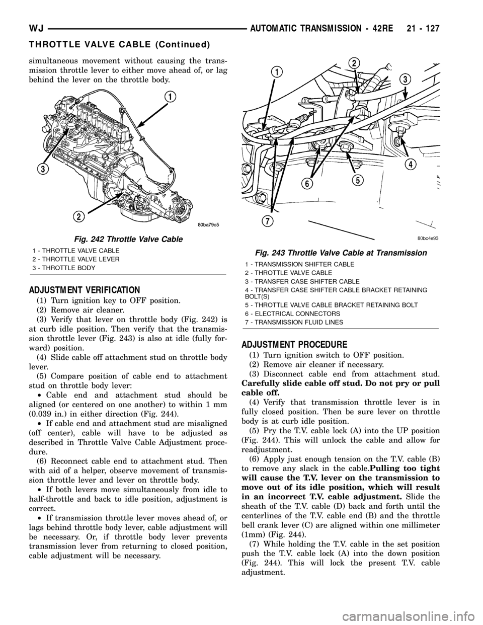
ADJUSTMENT VERIFICATION
(1) Turn ignition key to OFF position.
(2) Remove air cleaner.
(3) Verify that lever on throttle body (Fig. 242) is
at curb idle position. Then verify that the transmis-
sion throttle lever (Fig. 243) is also at idle (fully for-
ward) position.
(4) Slide cable off attachment stud on throttle body
lever.
(5) Compare position of cable end to attachment
stud on throttle body lever:
²Cable end and attachment stud should be
aligned (or centered on one another) to within 1 mm
(0.039 in.) in either direction (Fig. 244).
²If cable end and attachment stud are misaligned
(off center), cable will have to be adjusted as
described in Throttle Valve Cable Adjustment proce-
dure.
(6) Reconnect cable end to attachment stud. Then
with aid of a helper, observe movement of transmis-
sion throttle lever and lever on throttle body.
²If both levers move simultaneously from idle to
half-throttle and back to idle position, adjustment is
correct.
²If transmission throttle lever moves ahead of, or
lags behind throttle body lever, cable adjustment will
be necessary. Or, if throttle body lever prevents
transmission lever from returning to closed position,
cable adjustment will be necessary.
ADJUSTMENT PROCEDURE
(1) Turn ignition switch to OFF position.
(2) Remove air cleaner if necessary.
(3) Disconnect cable end from attachment stud.
Carefully slide cable off stud. Do not pry or pull
cable off.
(4) Verify that transmission throttle lever is in
fully closed position. Then be sure lever on throttle
body is at curb idle position.
(5) Pry the T.V. cable lock (A) into the UP position
(Fig. 244). This will unlock the cable and allow for
readjustment.
(6) Apply just enough tension on the T.V. cable (B)
to remove any slack in the cable.Pulling too tight
will cause the T.V. lever on the transmission to
move out of its idle position, which will result
in an incorrect T.V. cable adjustment.Slide the
sheath of the T.V. cable (D) back and forth until the
centerlines of the T.V. cable end (B) and the throttle
bell crank lever (C) are aligned within one millimeter
(1mm) (Fig. 244).
(7) While holding the T.V. cable in the set position
push the T.V. cable lock (A) into the down position
(Fig. 244). This will lock the present T.V. cable
adjustment.
Fig. 242 Throttle Valve Cable
1 - THROTTLE VALVE CABLE
2 - THROTTLE VALVE LEVER
3 - THROTTLE BODYFig. 243 Throttle Valve Cable at Transmission
1 - TRANSMISSION SHIFTER CABLE
2 - THROTTLE VALVE CABLE
3 - TRANSFER CASE SHIFTER CABLE
4 - TRANSFER CASE SHIFTER CABLE BRACKET RETAINING
BOLT(S)
5 - THROTTLE VALVE CABLE BRACKET RETAINING BOLT
6 - ELECTRICAL CONNECTORS
7 - TRANSMISSION FLUID LINES
WJAUTOMATIC TRANSMISSION - 42RE 21 - 127
THROTTLE VALVE CABLE (Continued)