2003 JEEP GRAND CHEROKEE washer fluid
[x] Cancel search: washer fluidPage 1058 of 2199
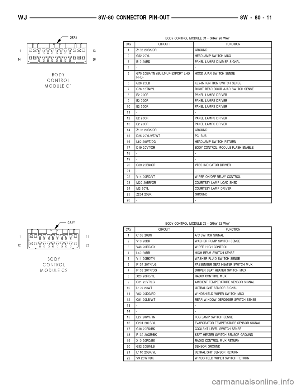
BODY CONTROL MODULE C1 - GRAY 26 WAY
CAV CIRCUIT FUNCTION
1 Z132 20BK/OR GROUND
2 G52 20YL HEADLAMP SWITCH MUX
3 E19 20RD PANEL LAMPS DIMMER SIGNAL
4- -
5 G70 20BR/TN (BUILT-UP-EXPORT LHD
RHD)HOOD AJAR SWITCH SENSE
6 G26 20LB KEY-IN IGNITION SWITCH SENSE
7 G76 18TN/YL RIGHT REAR DOOR AJAR SWITCH SENSE
8 E2 20OR PANEL LAMPS DRIVER
9 E2 20OR PANEL LAMPS DRIVER
10 E2 20OR PANEL LAMPS DRIVER
11 - -
12 E2 20OR PANEL LAMPS DRIVER
13 E2 20OR PANEL LAMPS DRIVER
14 Z132 20BK/OR GROUND
15 D25 20YL/VT/WT PCI BUS
16 L80 20WT/DG HEADLAMP SWITCH RETURN
17 D19 20VT/OR BODY CONTROL MODULE FLASH ENABLE
18 - -
19 - -
20 G69 20BK/OR VTSS INDICATOR DRIVER
21 - -
22 V14 20RD/VT WIPER ON/OFF RELAY CONTROL
23 M20 20BR/OR COURTESY LAMP LOAD SHED
24 M2 20YL COURTESY LAMP DRIVER
25 Z234 20BK GROUND
26 - -
BODY CONTROL MODULE C2 - GRAY 22 WAY
CAV CIRCUIT FUNCTION
1 C103 20DG A/C SWITCH SIGNAL
2 V10 20BR WASHER PUMP SWITCH SENSE
3 V48 20RD/GY WIPER HIGH CONTROL
4 L40 20BR HIGH BEAM SWITCH SENSE
5 V11 20BK/TN WASHER FLUID SWITCH SENSE
6 P134 20TN/LG PASSENGER SEAT HEATER SWITCH MUX
7 P133 20TN/DG DRIVER SEAT HEATER SWITCH MUX
8 X20 20RD/YL RADIO CONTROL MUX
9 G31 20VT/LG AMBIENT TEMPERATURE SENSOR SIGNAL
10 L109 20WT ULTRALIGHT SENSOR SIGNAL
11 V52 20DG/RD WINDSHIELD WIPER SWITCH MUX
12 C81 20LB/WT REAR WINDOW DEFOGGER SWITCH SENSE
13 - -
14 - -
15 L27 20WT/TN FOG LAMP SWITCH SENSE
16 C201 20LB/YL EVAPORATOR TEMPERATURE SENSOR SIGNAL
17 G18 20PK/BK COOLANT LEVEL SWITCH SENSE
18 P132 20OR/BK SEAT HEATER SWITCH SENSOR GROUND
19 X10 20RD/BK RADIO CONTROL MUX RETURN
20 G32 20BK/LB SENSOR GROUND
21 L110 20BK/YL ULTRALIGHT SENSOR RETURN
22 V9 20WT/BK WINDSHIELD WIPER SWITCH RETURN
WJ8W-80 CONNECTOR PIN-OUT 8W - 80 - 11
Page 1174 of 2199
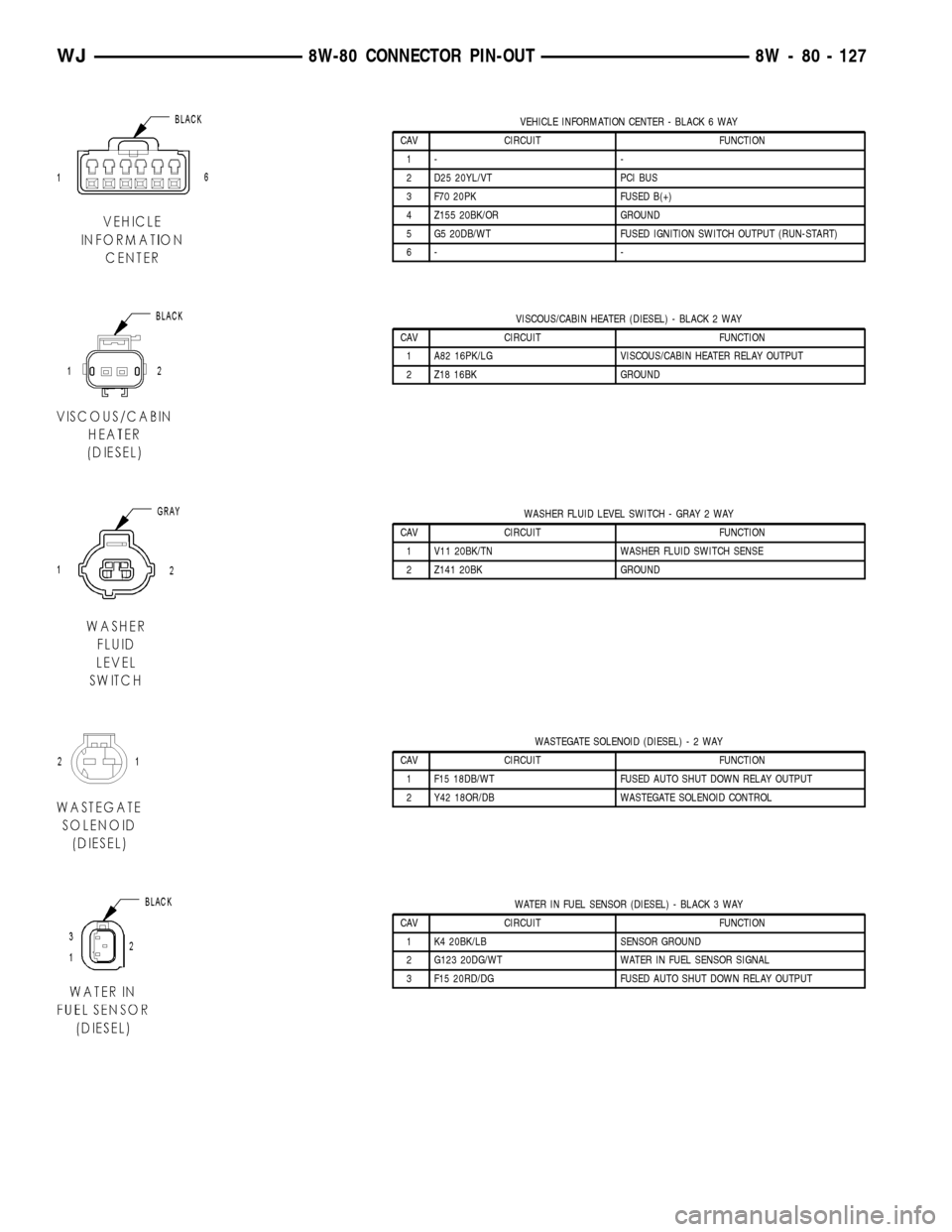
VEHICLE INFORMATION CENTER - BLACK 6 WAY
CAV CIRCUIT FUNCTION
1- -
2 D25 20YL/VT PCI BUS
3 F70 20PK FUSED B(+)
4 Z155 20BK/OR GROUND
5 G5 20DB/WT FUSED IGNITION SWITCH OUTPUT (RUN-START)
6- -
VISCOUS/CABIN HEATER (DIESEL) - BLACK 2 WAY
CAV CIRCUIT FUNCTION
1 A82 16PK/LG VISCOUS/CABIN HEATER RELAY OUTPUT
2 Z18 16BK GROUND
WASHER FLUID LEVEL SWITCH - GRAY 2 WAY
CAV CIRCUIT FUNCTION
1 V11 20BK/TN WASHER FLUID SWITCH SENSE
2 Z141 20BK GROUND
WASTEGATE SOLENOID (DIESEL)-2WAY
CAV CIRCUIT FUNCTION
1 F15 18DB/WT FUSED AUTO SHUT DOWN RELAY OUTPUT
2 Y42 18OR/DB WASTEGATE SOLENOID CONTROL
WATER IN FUEL SENSOR (DIESEL) - BLACK 3 WAY
CAV CIRCUIT FUNCTION
1 K4 20BK/LB SENSOR GROUND
2 G123 20DG/WT WATER IN FUEL SENSOR SIGNAL
3 F15 20RD/DG FUSED AUTO SHUT DOWN RELAY OUTPUT
WJ8W-80 CONNECTOR PIN-OUT 8W - 80 - 127
Page 1186 of 2199
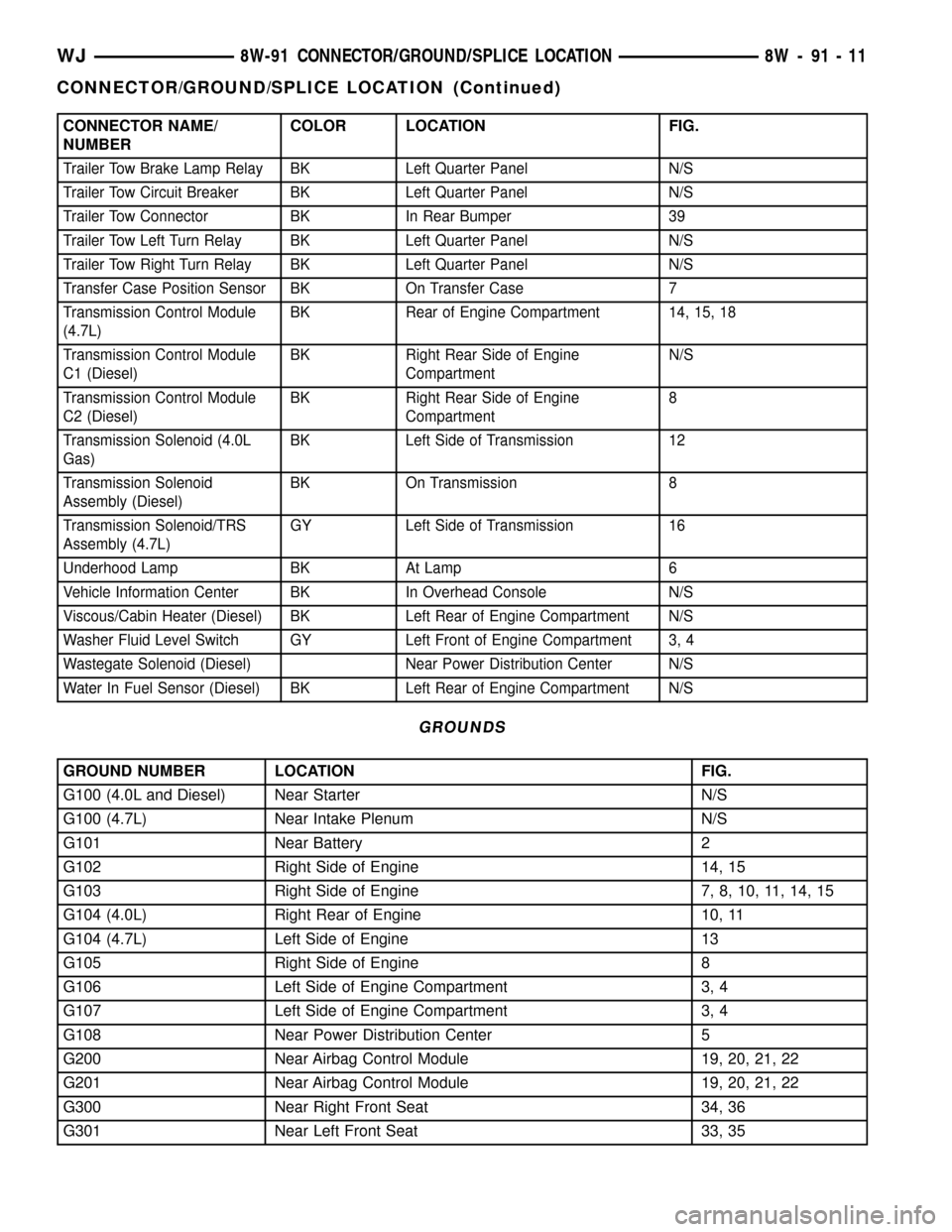
CONNECTOR NAME/
NUMBERCOLOR LOCATION FIG.
Trailer Tow Brake Lamp Relay BK Left Quarter Panel N/S
Trailer Tow Circuit Breaker BK Left Quarter Panel N/S
Trailer Tow Connector BK In Rear Bumper 39
Trailer Tow Left Turn Relay BK Left Quarter Panel N/S
Trailer Tow Right Turn Relay BK Left Quarter Panel N/S
Transfer Case Position Sensor BK On Transfer Case 7
Transmission Control Module
(4.7L)BK Rear of Engine Compartment 14, 15, 18
Transmission Control Module
C1 (Diesel)BK Right Rear Side of Engine
CompartmentN/S
Transmission Control Module
C2 (Diesel)BK Right Rear Side of Engine
Compartment8
Transmission Solenoid (4.0L
Gas)BK Left Side of Transmission 12
Transmission Solenoid
Assembly (Diesel)BK On Transmission 8
Transmission Solenoid/TRS
Assembly (4.7L)GY Left Side of Transmission 16
Underhood Lamp BK At Lamp 6
Vehicle Information Center BK In Overhead Console N/S
Viscous/Cabin Heater (Diesel) BK Left Rear of Engine Compartment N/S
Washer Fluid Level Switch GY Left Front of Engine Compartment 3, 4
Wastegate Solenoid (Diesel) Near Power Distribution Center N/S
Water In Fuel Sensor (Diesel) BK Left Rear of Engine Compartment N/S
GROUNDS
GROUND NUMBER LOCATION FIG.
G100 (4.0L and Diesel) Near Starter N/S
G100 (4.7L) Near Intake Plenum N/S
G101 Near Battery 2
G102 Right Side of Engine 14, 15
G103 Right Side of Engine 7, 8, 10, 11, 14, 15
G104 (4.0L) Right Rear of Engine 10, 11
G104 (4.7L) Left Side of Engine 13
G105 Right Side of Engine 8
G106 Left Side of Engine Compartment 3, 4
G107 Left Side of Engine Compartment 3, 4
G108 Near Power Distribution Center 5
G200 Near Airbag Control Module 19, 20, 21, 22
G201 Near Airbag Control Module 19, 20, 21, 22
G300 Near Right Front Seat 34, 36
G301 Near Left Front Seat 33, 35
WJ8W-91 CONNECTOR/GROUND/SPLICE LOCATION 8W - 91 - 11
CONNECTOR/GROUND/SPLICE LOCATION (Continued)
Page 1189 of 2199
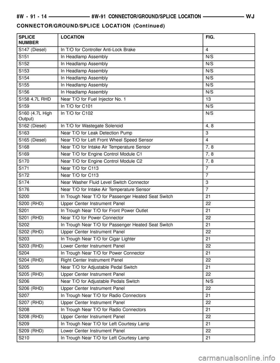
SPLICE
NUMBERLOCATION FIG.
S147 (Diesel) In T/O for Controller Anti-Lock Brake 4
S151 In Headlamp Assembly N/S
S152 In Headlamp Assembly N/S
S153 In Headlamp Assembly N/S
S154 In Headlamp Assembly N/S
S155 In Headlamp Assembly N/S
S156 In Headlamp Assembly N/S
S158 4.7L RHD Near T/O for Fuel Injector No. 1 13
S159 In T/O for C101 N/S
S160 (4.7L High
Output)In T/O for C102 N/S
S162 (Diesel) In T/O for Wastegate Solenoid 4, 8
S163 Near T/O for Leak Detection Pump 3
S165 (Diesel) Near T/O for Left Front Wheel Speed Sensor 4
S168 Near T/O for Intake Air Temperature Sensor 7, 8
S169 Near T/O for Engine Control Module C1 7, 8
S170 Near T/O for Engine Control Module C2 7, 8
S171 Near T/O for C113 7
S172 Near T/O for C113 7
S174 Near Washer Fluid Level Switch Connector 3
S176 Near T/O for Intake Air Temperature Sensor 7
S200 In Trough Near T/O for Passenger Heated Seat Switch 21
S200 (RHD) Upper Center Instrument Panel 22
S201 In Trough Near T/O for Front Power Outlet 21
S201 (RHD) Near T/O for Power Connector 22
S202 In Trough Near T/O for Passenger Heated Seat Switch 21
S202 (RHD) Upper Center Instrument Panel 22
S203 In Trough Near T/O for Cigar Lighter 21
S203 (RHD) Lower Center Instrument Panel 22
S204 In Trough Near T/O for Power Connector 21
S204 (RHD) Right Center Instrument Panel 22
S205 Near T/O for Adjustable Pedal Switch 21
S205 (RHD) Upper Center Instrument Panel 22
S206 Near T/O for Adjustable Pedals Switch N/S
S206 (RHD) Upper Center Instrument Panel 22
S207 In Trough Near T/O for Radio Connectors 21
S207 (RHD) Upper Center Instrument Panel 22
S208 In Trough Near T/O for Radio Connectors 21
S208 (RHD) Upper Center Instrument Panel 22
S209 In Trough Near T/O for Left Courtesy Lamp 21
S209 (RHD) Lower Center Instrument Panel 22
S210 In Trough Near T/O for Left Courtesy Lamp 21
8W - 91 - 14 8W-91 CONNECTOR/GROUND/SPLICE LOCATIONWJ
CONNECTOR/GROUND/SPLICE LOCATION (Continued)
Page 1310 of 2199
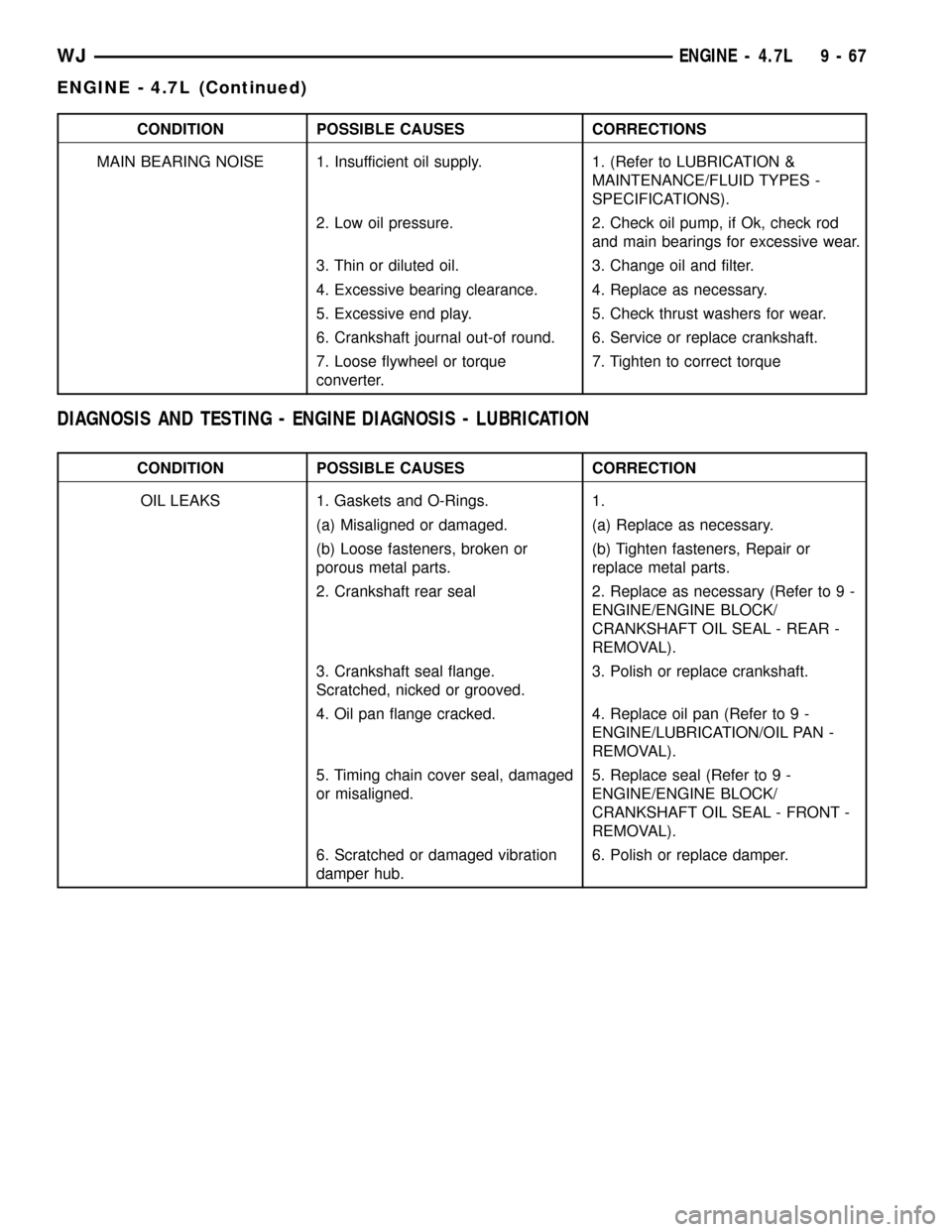
CONDITION POSSIBLE CAUSES CORRECTIONS
MAIN BEARING NOISE 1. Insufficient oil supply. 1. (Refer to LUBRICATION &
MAINTENANCE/FLUID TYPES -
SPECIFICATIONS).
2. Low oil pressure. 2. Check oil pump, if Ok, check rod
and main bearings for excessive wear.
3. Thin or diluted oil. 3. Change oil and filter.
4. Excessive bearing clearance. 4. Replace as necessary.
5. Excessive end play. 5. Check thrust washers for wear.
6. Crankshaft journal out-of round. 6. Service or replace crankshaft.
7. Loose flywheel or torque
converter.7. Tighten to correct torque
DIAGNOSIS AND TESTING - ENGINE DIAGNOSIS - LUBRICATION
CONDITION POSSIBLE CAUSES CORRECTION
OIL LEAKS 1. Gaskets and O-Rings. 1.
(a) Misaligned or damaged. (a) Replace as necessary.
(b) Loose fasteners, broken or
porous metal parts.(b) Tighten fasteners, Repair or
replace metal parts.
2. Crankshaft rear seal 2. Replace as necessary (Refer to 9 -
ENGINE/ENGINE BLOCK/
CRANKSHAFT OIL SEAL - REAR -
REMOVAL).
3. Crankshaft seal flange.
Scratched, nicked or grooved.3. Polish or replace crankshaft.
4. Oil pan flange cracked. 4. Replace oil pan (Refer to 9 -
ENGINE/LUBRICATION/OIL PAN -
REMOVAL).
5. Timing chain cover seal, damaged
or misaligned.5. Replace seal (Refer to 9 -
ENGINE/ENGINE BLOCK/
CRANKSHAFT OIL SEAL - FRONT -
REMOVAL).
6. Scratched or damaged vibration
damper hub.6. Polish or replace damper.
WJENGINE - 4.7L 9 - 67
ENGINE - 4.7L (Continued)
Page 1553 of 2199

(36) Compress rear servo spring retainer about
1/16 inch with Valve Spring Compressor C-3422-B
(Fig. 38).
(37) Remove rear servo spring retainer snap-ring.
Then remove compressor tools and remove rear servo
spring and piston.
(38) Inspect transmission components.
NOTE: To Service the overrunning clutch cam or
overdrive piston retainer, refer to the Overrunning
Clutch Cam service procedure in this section.
CLEANING
Clean the case in a solvent tank. Flush the case
bores and fluid passages thoroughly with solvent.
Dry the case and all fluid passages with compressed
air. Be sure all solvent is removed from the case and
that all fluid passages are clear.
NOTE: Do not use shop towels or rags to dry the
case (or any other transmission component) unless
they are made from lint-free materials. Lint will stick
to case surfaces and transmission components and
circulate throughout the transmission after assem-
bly. A sufficient quantity of lint can block fluid pas-
sages and interfere with valve body operation.Lubricate transmission parts with MopartATF +4,
type 9602, transmission fluid during overhaul and
assembly. Use petroleum jelly, MopartDoor Ease, or
Ru-GlydeŸ to prelubricate seals, O-rings, and thrust
washers. Petroleum jelly can also be used to hold
parts in place during reassembly.
INSPECTION
Inspect the case for cracks, porous spots, worn
bores, or damaged threads. Damaged threads can be
repaired with Helicoil thread inserts. However, the
case will have to be replaced if it exhibits any type of
damage or wear.
Lubricate the front band adjusting screw threads
with petroleum jelly and thread the screw part-way
into the case. Be sure the screw turns freely.
Inspect the transmission bushings during overhaul.
Bushing condition is important as worn, scored bush-
ings contribute to low pressures, clutch slip and
accelerated wear of other components. However, do
not replace bushings as a matter of course. Replace
bushings only when they are actually worn, or
scored.
Use recommended tools to replace bushings. The
tools are sized and designed to remove, install, and
seat bushings correctly. The bushing replacement
tools are included in Bushing Tool Set C-3887-B.
Pre-sized service bushings are available for
replacement purposes. Only the sun gear bushings
are not serviced.
The use of crocus cloth is permissible where neces-
sary, providing it is used carefully. When used on
shafts, or valves, use extreme care to avoid rounding
off sharp edges. Sharp edges are vital as they pre-
vent foreign matter from getting between the valve
and valve bore.
Do not reuse oil seals, gaskets, seal rings, or
O-rings during overhaul. Replace these parts as a
matter of course. Also do not reuse snap rings or
E-clips that are bent or distorted. Replace these parts
as well.
ASSEMBLY
Do not allow dirt, grease, or foreign material to
enter the case or transmission components during
assembly. Keep the transmission case and compo-
nents clean. Also make sure the tools and workbench
area used for assembly operations are equally clean.
Shop towels used for wiping off tools and hands
must be made fromlint freematerial. Lint will stick
to transmission parts and could interfere with valve
operation, or even restrict fluid passages.
Lubricate the transmission components with
Moparttransmission fluid during reassembly. Use
MopartDoor Ease, or Ru-GlydeŸ on seals and
O-rings to ease installation.
Fig. 38 Compressing Rear Servo Spring
1 - FRONT SERVO SNAP-RING
2 - REAR SERVO SNAP-RING
3 - SPECIAL TOOL
21 - 34 AUTOMATIC TRANSMISSION - 42REWJ
AUTOMATIC TRANSMISSION - 42RE (Continued)
Page 1554 of 2199

Petroleum jelly can also be used to hold thrust
washers, thrust plates and gaskets in position during
assembly. However,do notuse chassis grease, bear-
ing grease, white grease, or similar lubricants on any
transmission part. These types of lubricants can
eventually block or restrict fluid passages and inter-
fere with valve operation. Use petroleum jelly only.
Do not force parts into place. The transmission
components and subassemblies are easily installed by
hand when properly aligned.
If a part seems extremely difficult to install, it is
either misaligned or incorrectly assembled. Also ver-
ify that thrust washers, thrust plates and seal rings
are correctly positioned before assembly. These parts
can interfere with proper assembly if mis-positioned.
The planetary geartrain, front/rear clutch assem-
blies and oil pump are all much easier to install
when the transmission case is upright.
(1) Install rear servo piston, spring and retainer
(Fig. 39). Install spring on top of servo piston and
install retainer on top of spring.
(2) Install front servo piston assembly, servo
spring and rod guide (Fig. 40).
(3) Compress front/rear servo springs with Valve
Spring Compressor C-3422-B and install each servo
snap-ring (Fig. 41).
(4) Lubricate clutch cam rollers with transmission
fluid.
(5) Install rear band in case (Fig. 42). Be sure twin
lugs on band are seated against reaction pin.
(6) Install low-reverse drum and check overrun-
ning clutch operation as follows:(a) Lubricate overrunning clutch race (on drum
hub) with transmission fluid.
(b) Guide drum through rear band.
(c) Tilt drum slightly and start race (on drum
hub) into overrunning clutch rollers.
(d) Press drum rearward and turn it in clock-
wise direction until drum seats in overrunning
clutch (Fig. 43).
Fig. 39 Rear Servo Components
1 - SERVO PISTON
2 - PISTON SPRING
3 - SNAP-RING
4 - RETAINER
5 - PISTON SEAL
Fig. 40 Front Servo Components
1 - PISTON SEAL RINGS
2 - SERVO PISTON
3 - SNAP-RING
4 - ROD GUIDE
5 - SPRING
6 - ROD
Fig. 41 Compressing Front/Rear Servo Springs
1 - SPRING COMPRESSOR TOOL C-3422-B
2 - ROD GUIDE SNAP-RING
WJAUTOMATIC TRANSMISSION - 42RE 21 - 35
AUTOMATIC TRANSMISSION - 42RE (Continued)
Page 1574 of 2199
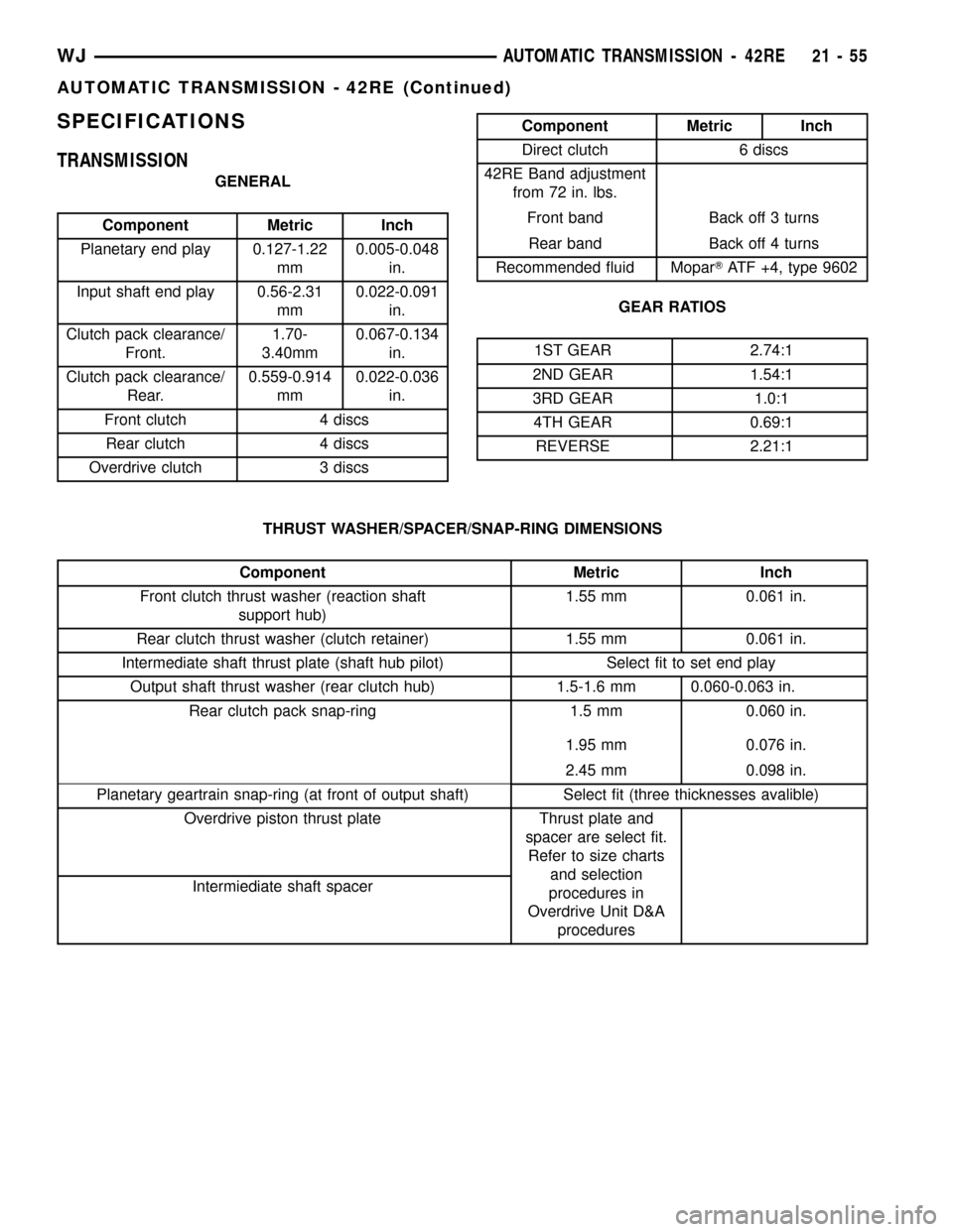
SPECIFICATIONS
TRANSMISSION
GENERAL
Component Metric Inch
Planetary end play 0.127-1.22
mm0.005-0.048
in.
Input shaft end play 0.56-2.31
mm0.022-0.091
in.
Clutch pack clearance/
Front.1.70-
3.40mm0.067-0.134
in.
Clutch pack clearance/
Rear.0.559-0.914
mm0.022-0.036
in.
Front clutch 4 discs
Rear clutch 4 discs
Overdrive clutch 3 discs
Component Metric Inch
Direct clutch 6 discs
42RE Band adjustment
from 72 in. lbs.
Front band Back off 3 turns
Rear band Back off 4 turns
Recommended fluid MoparTATF +4, type 9602
GEAR RATIOS
1ST GEAR 2.74:1
2ND GEAR 1.54:1
3RD GEAR 1.0:1
4TH GEAR 0.69:1
REVERSE 2.21:1
THRUST WASHER/SPACER/SNAP-RING DIMENSIONS
Component Metric Inch
Front clutch thrust washer (reaction shaft
support hub)1.55 mm 0.061 in.
Rear clutch thrust washer (clutch retainer) 1.55 mm 0.061 in.
Intermediate shaft thrust plate (shaft hub pilot) Select fit to set end play
Output shaft thrust washer (rear clutch hub) 1.5-1.6 mm 0.060-0.063 in.
Rear clutch pack snap-ring 1.5 mm 0.060 in.
1.95 mm 0.076 in.
2.45 mm 0.098 in.
Planetary geartrain snap-ring (at front of output shaft) Select fit (three thicknesses avalible)
Overdrive piston thrust plate Thrust plate and
spacer are select fit.
Refer to size charts
and selection
procedures in
Overdrive Unit D&A
procedures Intermiediate shaft spacer
WJAUTOMATIC TRANSMISSION - 42RE 21 - 55
AUTOMATIC TRANSMISSION - 42RE (Continued)