2003 JEEP GRAND CHEROKEE Power mirror
[x] Cancel search: Power mirrorPage 1150 of 2199
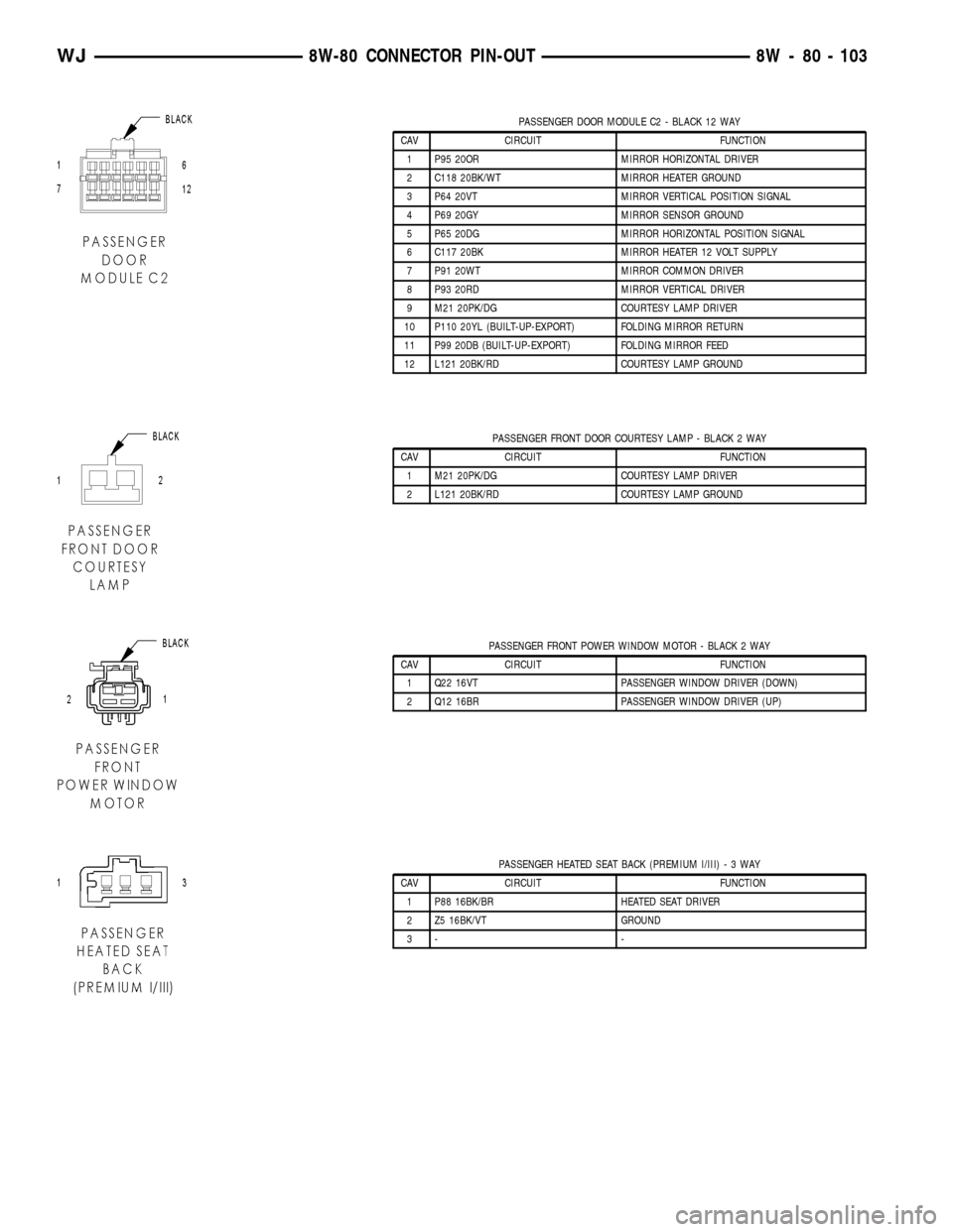
PASSENGER DOOR MODULE C2 - BLACK 12 WAY
CAV CIRCUIT FUNCTION
1 P95 20OR MIRROR HORIZONTAL DRIVER
2 C118 20BK/WT MIRROR HEATER GROUND
3 P64 20VT MIRROR VERTICAL POSITION SIGNAL
4 P69 20GY MIRROR SENSOR GROUND
5 P65 20DG MIRROR HORIZONTAL POSITION SIGNAL
6 C117 20BK MIRROR HEATER 12 VOLT SUPPLY
7 P91 20WT MIRROR COMMON DRIVER
8 P93 20RD MIRROR VERTICAL DRIVER
9 M21 20PK/DG COURTESY LAMP DRIVER
10 P110 20YL (BUILT-UP-EXPORT) FOLDING MIRROR RETURN
11 P99 20DB (BUILT-UP-EXPORT) FOLDING MIRROR FEED
12 L121 20BK/RD COURTESY LAMP GROUND
PASSENGER FRONT DOOR COURTESY LAMP - BLACK 2 WAY
CAV CIRCUIT FUNCTION
1 M21 20PK/DG COURTESY LAMP DRIVER
2 L121 20BK/RD COURTESY LAMP GROUND
PASSENGER FRONT POWER WINDOW MOTOR - BLACK 2 WAY
CAV CIRCUIT FUNCTION
1 Q22 16VT PASSENGER WINDOW DRIVER (DOWN)
2 Q12 16BR PASSENGER WINDOW DRIVER (UP)
PASSENGER HEATED SEAT BACK (PREMIUM I/III)-3WAY
CAV CIRCUIT FUNCTION
1 P88 16BK/BR HEATED SEAT DRIVER
2 Z5 16BK/VT GROUND
3- -
WJ8W-80 CONNECTOR PIN-OUT 8W - 80 - 103
Page 1152 of 2199
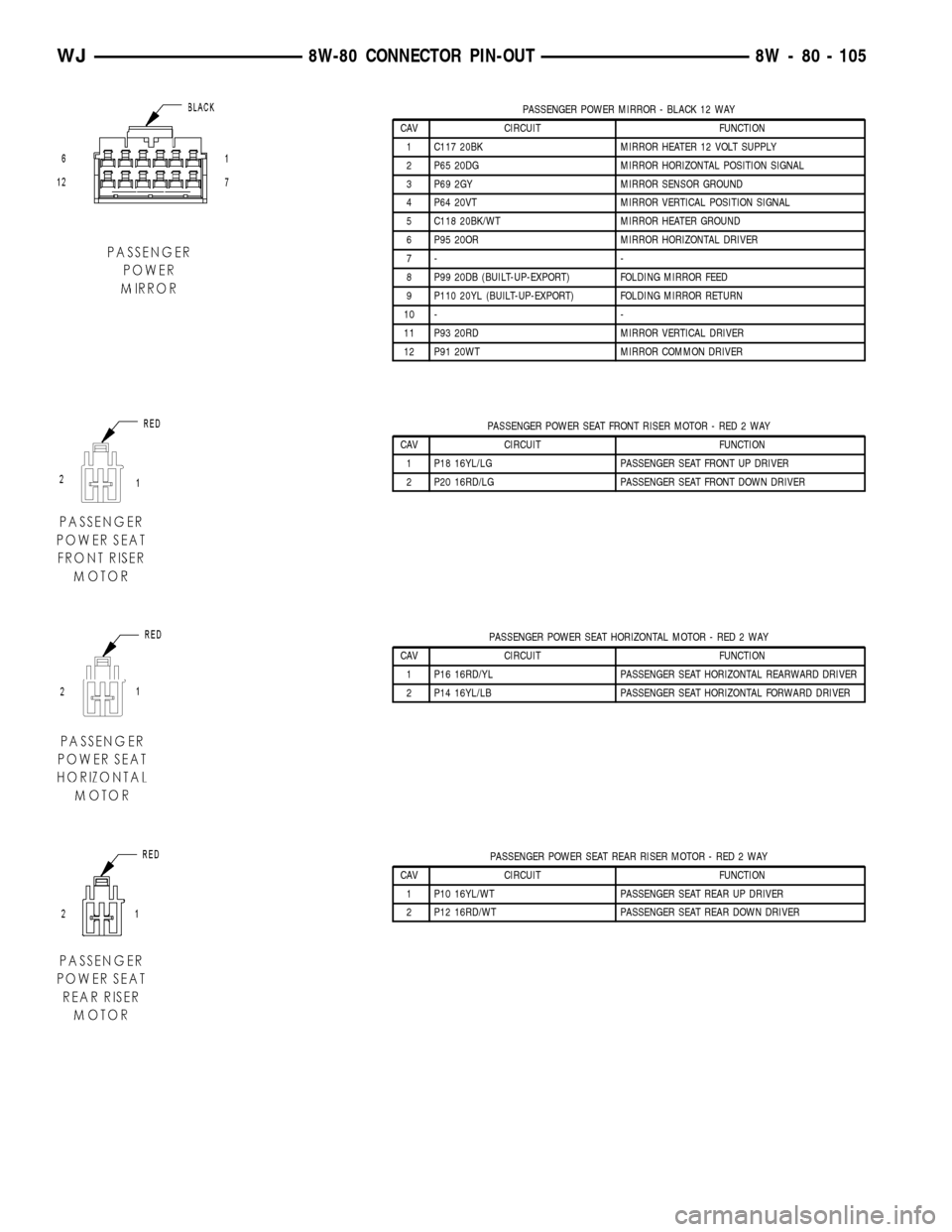
PASSENGER POWER MIRROR - BLACK 12 WAY
CAV CIRCUIT FUNCTION
1 C117 20BK MIRROR HEATER 12 VOLT SUPPLY
2 P65 20DG MIRROR HORIZONTAL POSITION SIGNAL
3 P69 2GY MIRROR SENSOR GROUND
4 P64 20VT MIRROR VERTICAL POSITION SIGNAL
5 C118 20BK/WT MIRROR HEATER GROUND
6 P95 20OR MIRROR HORIZONTAL DRIVER
7- -
8 P99 20DB (BUILT-UP-EXPORT) FOLDING MIRROR FEED
9 P110 20YL (BUILT-UP-EXPORT) FOLDING MIRROR RETURN
10 - -
11 P93 20RD MIRROR VERTICAL DRIVER
12 P91 20WT MIRROR COMMON DRIVER
PASSENGER POWER SEAT FRONT RISER MOTOR - RED 2 WAY
CAV CIRCUIT FUNCTION
1 P18 16YL/LG PASSENGER SEAT FRONT UP DRIVER
2 P20 16RD/LG PASSENGER SEAT FRONT DOWN DRIVER
PASSENGER POWER SEAT HORIZONTAL MOTOR - RED 2 WAY
CAV CIRCUIT FUNCTION
1 P16 16RD/YL PASSENGER SEAT HORIZONTAL REARWARD DRIVER
2 P14 16YL/LB PASSENGER SEAT HORIZONTAL FORWARD DRIVER
PASSENGER POWER SEAT REAR RISER MOTOR - RED 2 WAY
CAV CIRCUIT FUNCTION
1 P10 16YL/WT PASSENGER SEAT REAR UP DRIVER
2 P12 16RD/WT PASSENGER SEAT REAR DOWN DRIVER
WJ8W-80 CONNECTOR PIN-OUT 8W - 80 - 105
Page 1179 of 2199
CONNECTOR NAME/
NUMBERCOLOR LOCATION FIG.
Coil On Plug NO. 8 (4.7L) BK Right Side of Engine Near Fuel
Injector No.814, 15
Coil Rail (4.0L) BK Right Rear of Engine 10, 11
Compact Disc Changer BK Near Radio N/S
Compact Disc Changer BK Right Rear Quarter Panel 37
Controller Antilock Brake BK Left Front Engine Compartment 3, 4
Coolant Level Sensor LT GY Right Rear of Engine 5
Crankcase Heater (Diesel) BK Near T/O for G105 8
Crankshaft Position Sensor
(Diesel)BK Rear of Engine Near Transmission
Bell HousingN/S
Crankshaft Position Sensor
(Gas)BK Rear of Engine Near Transmission
Bell Housing10, 11, 14, 15, 17
Data Link Connector BK Under Lower Driver's Side of
Instrument Panel20, 21, 22
Diagnostic Junction Port BK At Steering Column 23
Driver Airbag Squib 1 BK In Steering Wheel N/S
Driver Airbag Squib 2 BK In Steering Wheel N/S
Driver Blend Door Motor/
Actuator (AZC)BK On HVAC Housing N/S
Driver Cylinder Lock Switch GY In Driver Door 24, 25
Driver Door Lock Motor/Ajar
SwitchBK In Driver Door 24, 25
Driver Door Module - C1 WT In Driver Door 24, 25
Driver Door Module - C2 BK In Driver Door N/S
Driver Door Module - C3 BK In Driver Door N/S
Driver Front Door Courtesy
LampBK In Driver Door N/S
Driver Front Power Window
MotorBK In Driver Door 24, 25
Driver Heated Seat Back
(Premium I/III)GN At Driver Seat N/S
Driver Heated Seat Cushion
(Premium I/III)BK At Driver Seat N/S
Driver Heated Seat Switch WT Center of Instrument Panel 19 20, 21
Driver Lumbar Motor
(Midline/Premium)BK At Driver Seat N/S
Driver Lumbar Switch
(Midline/Premium)WT At Driver Seat N/S
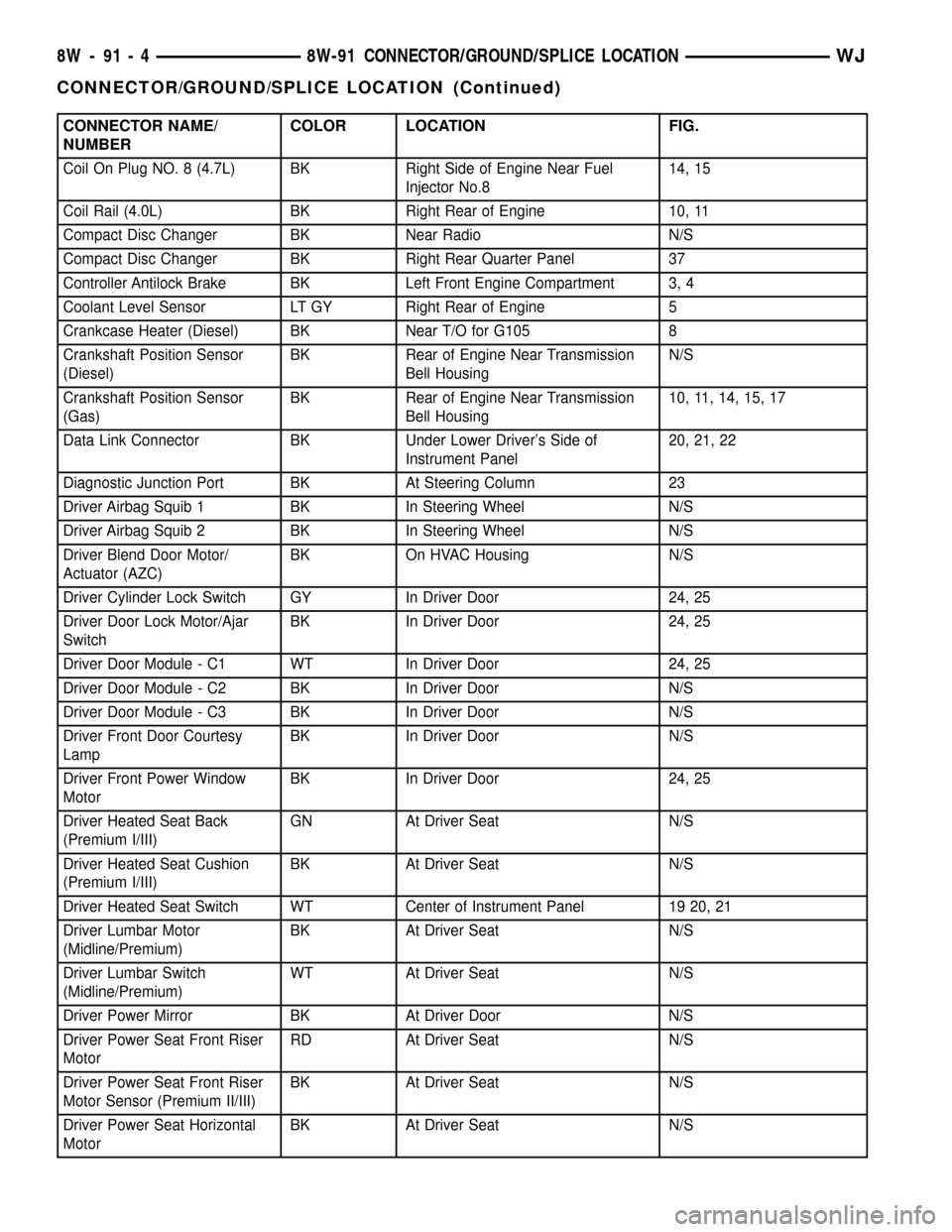
Driver Power Mirror BK At Driver Door N/S
Driver Power Seat Front Riser
MotorRD At Driver Seat N/S
Driver Power Seat Front Riser
Motor Sensor (Premium II/III)BK At Driver Seat N/S
Driver Power Seat Horizontal
MotorBK At Driver Seat N/S
8W - 91 - 4 8W-91 CONNECTOR/GROUND/SPLICE LOCATIONWJ
CONNECTOR/GROUND/SPLICE LOCATION (Continued)
Page 1183 of 2199
CONNECTOR NAME/
NUMBERCOLOR LOCATION FIG.
Output Speed Sensor (4.0L) GY Left Side of Transmission 12
Output Speed Sensor (4.7L) BK Left Side of Transmission 16
Overhead Map/Courtesy Lamp WT At Overhead Console N/S
Oxygen Sensor 1/1 Upstream
(4.0L)GY Left Side of Engine at Exhaust 9, 12
Oxygen Sensor 1/1 Upstream
(4.7L)GY Left Side of Engine at Exhaust 17
Oxygen Sensor 1/2
Downstream (4.0L)BK Rear of Transmission 9, 12
Oxygen Sensor 1/2
Downstream (4.7L)BK Rear of Transmission 17
Oxygen Sensor 2/1 Upstream Rear of Transmission N/S
Oxygen Sensor 2/2
DownstreamRear of Transmission N/S
Park Brake Switch Center Console Area, Near Airbag
Control Module20, 21, 22
Park/Neutral Position Switch
(4.0L)BK Left Side of Transmission 12
Park/Neutral Position Switch
(Diesel)BK Left Side of Transmission N/S
Passenger Airbag YL Passenger Side of Instrument Panel 19, 20
Passenger Blend Door
Motor/Actuator (AZC)BK Passenger Side of Instrument Panel N/S
Passenger Door Lock
Motor/Ajar SwitchBK In Passenger Door 26, 27
Passenger Door Module - C1 WT In Passenger Door 26, 27
Passenger Door Module - C2 BK In Passenger Door N/S
Passenger Front Door
Courtesy LampBK In Passenger Door N/S
Passenger Front Power
Window MotorBK In Passenger Door 26, 27
Passenger Heated Seat Back
(Premium I/III)GN At Passenger Seat N/S
Passenger Heated Seat
Cushion (Premium I/III)BK At Passenger Seat N/S
Passenger Heated Seat Switch BK Center of Instrument Panel 19, 20, 21
Passenger Lumbar Motor
(Midline/Premium)BK At Passenger Seat N/S
Passenger Lumbar Switch
(Midline/Premium)WT At Passenger Seat N/S
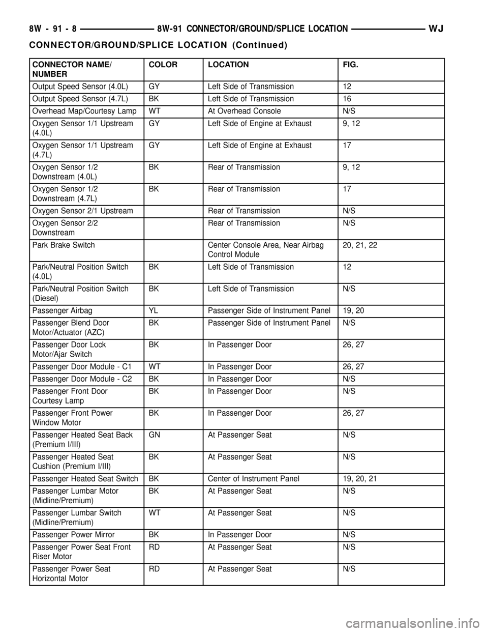
Passenger Power Mirror BK In Passenger Door N/S
Passenger Power Seat Front
Riser MotorRD At Passenger Seat N/S
Passenger Power Seat
Horizontal MotorRD At Passenger Seat N/S
8W - 91 - 8 8W-91 CONNECTOR/GROUND/SPLICE LOCATIONWJ
CONNECTOR/GROUND/SPLICE LOCATION (Continued)
Page 1191 of 2199
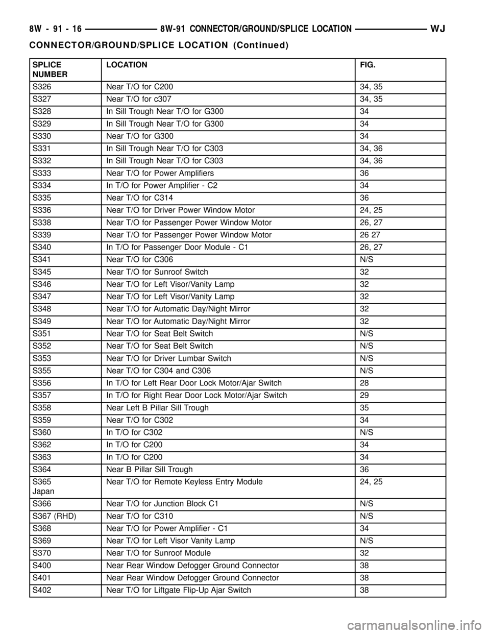
SPLICE
NUMBERLOCATION FIG.
S326 Near T/O for C200 34, 35
S327 Near T/O for c307 34, 35
S328 In Sill Trough Near T/O for G300 34
S329 In Sill Trough Near T/O for G300 34
S330 Near T/O for G300 34
S331 In Sill Trough Near T/O for C303 34, 36
S332 In Sill Trough Near T/O for C303 34, 36
S333 Near T/O for Power Amplifiers 36
S334 In T/O for Power Amplifier - C2 34
S335 Near T/O for C314 36
S336 Near T/O for Driver Power Window Motor 24, 25
S338 Near T/O for Passenger Power Window Motor 26, 27
S339 Near T/O for Passenger Power Window Motor 26 27
S340 In T/O for Passenger Door Module - C1 26, 27
S341 Near T/O for C306 N/S
S345 Near T/O for Sunroof Switch 32
S346 Near T/O for Left Visor/Vanity Lamp 32
S347 Near T/O for Left Visor/Vanity Lamp 32
S348 Near T/O for Automatic Day/Night Mirror 32
S349 Near T/O for Automatic Day/Night Mirror 32
S351 Near T/O for Seat Belt Switch N/S
S352 Near T/O for Seat Belt Switch N/S
S353 Near T/O for Driver Lumbar Switch N/S
S355 Near T/O for C304 and C306 N/S
S356 In T/O for Left Rear Door Lock Motor/Ajar Switch 28
S357 In T/O for Right Rear Door Lock Motor/Ajar Switch 29
S358 Near Left B Pillar Sill Trough 35
S359 Near T/O for C302 34
S360 In T/O for C302 N/S
S362 In T/O for C200 34
S363 In T/O for C200 34
S364 Near B Pillar Sill Trough 36
S365
JapanNear T/O for Remote Keyless Entry Module 24, 25
S366 Near T/O for Junction Block C1 N/S
S367 (RHD) Near T/O for C310 N/S
S368 Near T/O for Power Amplifier - C1 34
S369 Near T/O for Left Visor Vanity Lamp N/S
S370 Near T/O for Sunroof Module 32
S400 Near Rear Window Defogger Ground Connector 38
S401 Near Rear Window Defogger Ground Connector 38
S402 Near T/O for Liftgate Flip-Up Ajar Switch 38
8W - 91 - 16 8W-91 CONNECTOR/GROUND/SPLICE LOCATIONWJ
CONNECTOR/GROUND/SPLICE LOCATION (Continued)
Page 1890 of 2199
INSTALLATION
(1) Connect lock cylinder switch, if equipped.
(2) Position lock cylinder in door handle.
(3) Position lock cylinder retainer and install
screw (Fig. 13).
(4) Install outside door handle, refer to (Refer to
23 - BODY/DOOR - FRONT/EXTERIOR HANDLE -
INSTALLATION).
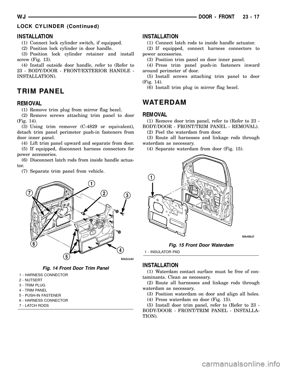
TRIM PANEL
REMOVAL
(1) Remove trim plug from mirror flag bezel.
(2) Remove screws attaching trim panel to door
(Fig. 14).
(3) Using trim remover (C-4829 or equivalent),
detach trim panel perimeter push-in fasteners from
door inner panel.
(4) Lift trim panel upward and separate from door.
(5) If equipped, disconnect harness connectors for
power accessories.
(6) Disconnect latch rods from inside handle actua-
tor.
(7) Separate trim panel from vehicle.
INSTALLATION
(1) Connect latch rods to inside handle actuator.
(2) If equipped, connect harness connectors to
power accessories.
(3) Position trim panel on door inner panel.
(4) Press trim panel push-in fasteners inward
around perimeter of door.
(5) Install screws attaching trim panel to door
(Fig. 14).
(6) Install trim plug in mirror flag bezel.
WATERDAM
REMOVAL
(1) Remove door trim panel, refer to (Refer to 23 -
BODY/DOOR - FRONT/TRIM PANEL - REMOVAL).
(2) Peel the waterdam from door.
(3) Route all harnesses and linkage rods through
waterdam as necessary.
(4) Separate waterdam from door (Fig. 15).
INSTALLATION
(1) Waterdam contact surface must be free of con-
taminants. Clean as necessary.
(2) Route all harnesses and linkage rods through
waterdam as necessary.
(3) Position waterdam on door and align all holes.
(4) Press waterdam on door (Fig. 15).
(5) Install door trim panel, refer to (Refer to 23 -
BODY/DOOR - FRONT/TRIM PANEL - INSTALLA-
TION).Fig. 14 Front Door Trim Panel
1 - HARNESS CONNECTOR
2 - NUTSERT
3 - TRIM PLUG
4 - TRIM PANEL
5 - PUSH-IN FASTENER
6 - HARNESS CONNECTOR
7 - LATCH RODS
Fig. 15 Front Door Waterdam
1 - INSULATOR PAD
WJDOOR - FRONT 23 - 17
LOCK CYLINDER (Continued)
Page 1904 of 2199
(4) Remove the screws attaching the supports to
the roof panel.
(5) Separate the supports from the roof panel.
NOTE: If a crossbar needs to be serviced, the for-
ward or rearward supports will have to be removed.
INSTALLATION
(1) Position the supports on the roof panel and
install the screw. Be sure that the gasket is properly
seated.
(2) Position the luggage rack on the supports.
(3) Install the screws attaching the side rails to
the supports.
(4) Position the supports covers on the supports
and press into place.
SIDE VIEW MIRROR GLASS
REMOVAL
(1) With damaged mirror still on vehicle, position
mirror glass down and centered.
(2) Position a wide leverage device between the
bottom edge of the glass and the mirror shell.
(3) Firmly apply pressure in an upward direction
until glass assembly disengages from adapter plate.
(4) Disconnect the heater wire terminal, if
equipped, or the EC plug, if equipped.
INSTALLATION
(1) Connect the heater wire terminal or the EC
plug, if equipped.
(2) Position the replacement glass in the mirror
shell and align the four snap tabs with the four cav-
ities in the shell.
(3) Apply firm pressure inward until the replace-
ment glass assembly engages with the adapter plate.
Correct assembly will result in a firm click. Glass
assembly should exhibit even gaps to the shell when
complete.
(4) Pull lightly on corners of glass assembly to
ensure all four snaps are engaged and there is no
free play.
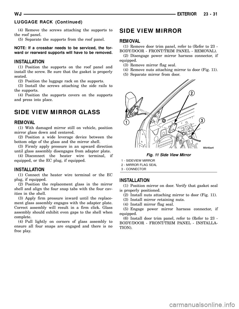
SIDE VIEW MIRROR
REMOVAL
(1) Remove door trim panel, refer to (Refer to 23 -
BODY/DOOR - FRONT/TRIM PANEL - REMOVAL).
(2) Disengage power mirror harness connector, if
equipped.
(3) Remove mirror flag seal.
(4) Remove nuts attaching mirror to door (Fig. 11).
(5) Separate mirror from door.
INSTALLATION
(1) Position mirror on door. Verify that gasket seal
is properly positioned.
(2) Install nuts attaching mirror to door (Fig. 11).
(3) Install mirror retaining nuts.
(4) Install mirror flag seal.
(5) Engage power mirror harness connector, if
equipped.
(6) Install door trim panel, refer to (Refer to 23 -
BODY/DOOR - FRONT/TRIM PANEL - INSTALLA-
TION).
Fig. 11 Side View Mirror
1 - SIDEVIEW MIRROR
2 - MIRROR FLAG SEAL
3 - CONNECTOR
WJEXTERIOR 23 - 31
LUGGAGE RACK (Continued)