2003 JEEP GRAND CHEROKEE Timing
[x] Cancel search: TimingPage 414 of 2199

CHIPPED ELECTRODE INSULATOR
A chipped electrode insulator usually results from
bending the center electrode while adjusting the
spark plug electrode gap. Under certain conditions,
severe detonation can also separate the insulator
from the center electrode (Fig. 29). Spark plugs with
this condition must be replaced.
PRE-IGNITION DAMAGE
Pre-ignition damage is usually caused by excessive
combustion chamber temperature. The center elec-
trode dissolves first and the ground electrode dis-
solves somewhat latter (Fig. 30). Insulators appear
relatively deposit free. Determine if the spark plug
has the correct heat range rating for the engine.Determine if ignition timing is over advanced or if
other operating conditions are causing engine over-
heating. (The heat range rating refers to the operat-
ing temperature of a particular type spark plug.
Spark plugs are designed to operate within specific
temperature ranges. This depends upon the thick-
ness and length of the center electrodes porcelain
insulator.)
CAUTION: If the engine is equipped with copper
core ground electrode, or platinum tipped spark
plugs, they must be replaced with the same type/
number spark plug as the original. If another spark
plug is substituted, pre-ignition will result.
Fig. 27 ELECTRODE GAP BRIDGING
1 - GROUND ELECTRODE
2 - DEPOSITS
3 - CENTER ELECTRODE
Fig. 28 SCAVENGER DEPOSITS
1 - GROUND ELECTRODE COVERED WITH WHITE OR
YELLOW DEPOSITS
2 - CENTER ELECTRODE
Fig. 29 CHIPPED ELECTRODE INSULATOR
1 - GROUND ELECTRODE
2 - CENTER ELECTRODE
3 - CHIPPED INSULATOR
Fig. 30 PRE-IGNITION DAMAGE
1 - GROUND ELECTRODE STARTING TO DISSOLVE
2 - CENTER ELECTRODE DISSOLVED
WJIGNITION CONTROL 8I - 17
SPARK PLUG (Continued)
Page 415 of 2199

SPARK PLUG OVERHEATING
Overheating is indicated by a white or gray center
electrode insulator that also appears blistered (Fig.
31). The increase in electrode gap will be consider-
ably in excess of 0.001 inch per 2000 miles of opera-
tion. This suggests that a plug with a cooler heat
range rating should be used. Over advanced ignition
timing, detonation and cooling system malfunctions
can also cause spark plug overheating.
CAUTION: If the engine is equipped with copper
core ground electrode, or platinum tipped spark
plugs, they must be replaced with the same type/
number spark plug as the original. If another spark
plug is substituted, pre-ignition will result.
REMOVAL
CAUTION: If equipped with a 4.7L H.O. (High-Out-
put) engine, never substitute the original platinum
tipped spark plug with a different part number. Seri-
ous engine damage may result.
On the 4.0L 6±cylinder engine, the spark plugs are
located below the coil rail assembly. On the 4.7L V±8
engine, each individual spark plug is located under
each ignition coil.
(1) 4.0L 6±Cylinder Engine: Prior to removing
spark plug, spray compressed air around spark plug
hole and area around spark plug. This will help pre-
vent foreign material from entering combustion
chamber.
(2) 4.7L V±8 Engine: Prior to removing spark plug,
spray compressed air around base of ignition coil at
cylinder head. This will help prevent foreign material
from entering combustion chamber.
(3) On the 4.0L engine the coil rail assembly must
be removed to gain access to any/all spark plug.
Refer to Ignition Coil Removal/Installation. On the4.7L V-8 engine each individual ignition coil must be
removed to gain access to each spark plug. Refer to
Ignition Coil Removal/Installation.
(4) Remove spark plug from cylinder head using a
quality socket with a rubber or foam insert. If
equipped with a 4.7L V-8 engine, also check condition
of coil o-ring and replace as necessary.
(5) Inspect spark plug condition. Refer to Spark
Plug Conditions.
CLEANING
Except 4.7L H.O. Engine:The plugs may be
cleaned using commercially available spark plug
cleaning equipment. After cleaning, file center elec-
trode flat with a small point file or jewelers file
before adjusting gap.
CAUTION: Never use a motorized wire wheel brush
to clean spark plugs. Metallic deposits will remain
on spark plug insulator and will cause plug misfire.
4.7L H.O. Engine:Never clean spark plugs on the
4.7L H.O. engine. Damage to the platinum rivet on
the center electrode will result.
INSTALLATION
CAUTION: The standard 4.7L V-8 engine is
equipped with copper core ground electrode spark
plugs. They must be replaced with the same type/
number spark plug as the original. If another spark
plug is substituted, pre-ignition will result.
CAUTION: If equipped with a 4.7L H.O. (High-Out-
put) engine, never substitute the original platinum
tipped spark plug with a different type/part number.
Serious engine damage may result.
Special care should be taken when installing spark
plugs into cylinder head spark plug wells. Be sure
plugs do not drop into plug wells as ground straps
may be bent resulting in a change in plug gap, or
electrodes can be damaged.
Always tighten spark plugs to specified torque. Over
tightening can cause distortion resulting in a change
in spark plug gap or a cracked porcelain insulator.
(1) Start spark plug into cylinder head by hand to
avoid cross threading.
(2) 4.0L 6±Cylinder Engine: Tighten spark plugs to
35-41 N´m (26-30 ft. lbs.) torque.
(3) 4.7L V±8 Engine: Tighten spark plugs to 27
N´m (20 ft. lbs.) torque.
(4)
4.7L V±8 Engine: Before installing coil(s), check
condition of coil o-ring and replace as necessary. To aid
in coil installation, apply silicone to coil o-ring.
(5) Install ignition coil(s). Refer to Ignition Coil
Removal/Installation.
Fig. 31 SPARK PLUG OVERHEATING
1 - BLISTERED WHITE OR GRAY COLORED INSULATOR
8I - 18 IGNITION CONTROLWJ
SPARK PLUG (Continued)
Page 612 of 2199

tem functions, as well as separate hard wired sense
inputs to the BCM for the high speed continuous
wipe and front washer system functions.
The front wiper and washer system will only oper-
ate when the ignition switch is in the Accessory or
On positions. Battery current is directed from a B(+)
fuse in the Power Distribution Center (PDC) to the
wiper and washer system circuit breaker in the Junc-
tion Block (JB) through a fused ignition switch out-
put (run-acc) circuit. The automatic resetting circuit
breaker then provides battery current through a
fused ignition switch output (run-acc) circuit to the
wiper on/off relay, and the park switch in the front
wiper motor. A separate fuse in the JB provides bat-
tery current through another fused ignition switch
output (run-acc) circuit to the right multi-function
switch. The right multi-function switch circuitry uses
this battery feed to directly control the operation of
the front washer pump/motor unit. The BCM uses
low side drivers to control front wiper system opera-
tion by energizing or de-energizing the wiper high/
low and wiper on/off relays.
The hard wired circuits and components of the
front wiper and washer system may be diagnosed
and tested using conventional diagnostic tools and
procedures. However, conventional diagnostic meth-
ods may not prove conclusive in the diagnosis of the
Body Control Module (BCM), or the inputs to or out-
puts from the BCM that control the front wiper and
washer system operating modes. The most reliable,
efficient, and accurate means to diagnose the BCM,
or the BCM inputs and outputs related to the various
front wiper and washer system operating modes
requires the use of a DRBIIItscan tool. Refer to the
appropriate diagnostic information.
Following are paragraphs that briefly describe the
operation of each of the front wiper and washer sys-
tem operating modes.
CONTINUOUS WIPE MODE
When the Low position of the control knob on the
control stalk of the right (wiper) multi-function
switch is selected, the Body Control Module (BCM)
energizes the wiper on/off relay. This directs battery
current through the normally open contacts of the
energized wiper on/off relay and the normally closed
contacts of the de-energized wiper high/low relay to
the low speed brush of the front wiper motor, causing
the front wipers to cycle at low speed. When the
High position of the control knob is selected, the
BCM energizes both the wiper on/off relay and the
wiper high/low relay. This directs battery current
through the normally open contacts of the energized
wiper on/off relay and the normally open contacts of
the energized wiper high/low relay to the high speedbrush of the front wiper motor, causing the front wip-
ers to cycle at high speed.
When the Off position of the control knob is
selected, the BCM de-energizes both the wiper on/off
and wiper high/low relays, then one of two events
will occur. The event that will occur depends upon
the position of the wiper blades on the windshield at
the moment that the control knob Off position is
selected. If the wiper blades are in the down position
on the windshield when the Off position is selected,
the park switch that is integral to the front wiper
motor is closed to ground and the wiper motor ceases
to operate. If the wiper blades are not in the down
position on the windshield at the moment the Off
position is selected, the park switch is closed to bat-
tery current from the fused ignition switch output
(run-acc) circuit of the front wiper motor. The park
switch directs this battery current to the low speed
brush of the wiper motor through the wiper park
switch sense circuit and the normally closed contacts
of the wiper on/off and wiper high/low relays. This
causes the wiper motor to continue running at low
speed until the wiper blades are in the down position
on the windshield and the park switch is again
closed to ground.
INTERMITTENT WIPE MODE
On models not equipped with the optional auto-
matic wiper system, when the control knob on the
control stalk of the right (wiper) multi-function
switch is moved to one of the five Delay interval posi-
tions, the BCM electronic intermittent wipe logic cir-
cuit responds by calculating the correct length of
time between wiper sweeps based upon the selected
delay interval input. The BCM monitors the chang-
ing state of the wiper motor park switch through a
hard wired front wiper park switch sense circuit
input. This input allows the BCM to determine the
proper intervals at which to energize and de-energize
the wiper on/off relay to operate the front wiper
motor intermittently for one low speed cycle at a
time. The BCM logic is also programmed to provide
an immediate wipe cycle and begin a new delay
interval timing cycle each time a shorter delay inter-
val is selected, and to add the remaining delay tim-
ing interval to the new delay interval timing before
the next wipe cycle occurs each time a longer delay
interval is selected.
The intermittent wipe mode delay times are speed
sensitive. The BCM monitors vehicle speed messages
received from the Powertrain Control Module (PCM)
over the Programmable Communications Interface
(PCI) data bus network in order to provide the speed
sensitive delay intervals. Above about sixteen kilome-
ters-per-hour (ten miles-per-hour) the delay is driver
adjustable from about one-half second to about eigh-
WJFRONT WIPERS/WASHERS 8R - 5
FRONT WIPERS/WASHERS (Continued)
Page 1245 of 2199

REMOVAL
REMOVAL - CAMSHAFT BEARINGS.......31
REMOVAL - CAMSHAFT................31
INSPECTION
INSPECTION - CAMSHAFT BEARINGS.....31
INSPECTION - CAMSHAFT..............31
INSTALLATION
INSTALLATION - CAMSHAFT BEARINGS . . . 32
INSTALLATION - CAMSHAFT............32
CONNECTING ROD BEARINGS
STANDARD PROCEDURE - FITTING
CONNECTING ROD BEARINGS..........33
CRANKSHAFT
DESCRIPTION.........................35
CRANKSHAFT MAIN BEARINGS
STANDARD PROCEDURE - FITTING
CRANKSHAFT MAIN BEARINGS..........36
REMOVAL.............................39
INSPECTION..........................40
INSTALLATION.........................40
CRANKSHAFT OIL SEAL - FRONT
REMOVAL.............................41
INSTALLATION.........................41
CRANKSHAFT OIL SEAL - REAR
REMOVAL.............................42
INSTALLATION.........................42
HYDRAULIC LIFTERS
DESCRIPTION.........................43
REMOVAL.............................43
CLEANING............................43
INSPECTION..........................43
INSTALLATION.........................43
PISTON & CONNECTING ROD
DESCRIPTION.........................44
STANDARD PROCEDURE - PISTON FITTING . 44
REMOVAL.............................45
INSTALLATION.........................46
PISTON RINGS
STANDARD PROCEDURE - PISTON RING
FITTING.............................47
VIBRATION DAMPER
REMOVAL.............................49
INSTALLATION.........................49STRUCTURAL SUPPORT
REMOVAL.............................49
INSTALLATION.........................50
LUBRICATION
DESCRIPTION.........................50
OPERATION...........................50
DIAGNOSIS AND TESTING
DIAGNOSIS AND TESTING - ENGINE OIL
PRESSURE..........................51
DIAGNOSIS AND TESTING - ENGINE OIL
LEAK...............................51
OIL
STANDARD PROCEDURE - ENGINE OIL
SERVICE............................53
OIL FILTER
REMOVAL.............................53
INSTALLATION.........................54
OIL PAN
DESCRIPTION.........................54
REMOVAL.............................54
INSTALLATION.........................55
ENGINE OIL PRESSURE SENSOR
DESCRIPTION.........................56
OPERATION...........................56
OIL PUMP
REMOVAL.............................56
INSTALLATION.........................57
INTAKE MANIFOLD
DESCRIPTION.........................57
DIAGNOSIS AND TESTING - INTAKE
MANIFOLD LEAKAGE..................57
REMOVAL.............................57
INSTALLATION.........................57
EXHAUST MANIFOLD
DESCRIPTION.........................58
REMOVAL.............................58
INSTALLATION.........................58
TIMING BELT / CHAIN COVER(S)
REMOVAL.............................58
INSTALLATION.........................58
TIMING BELT/CHAIN AND SPROCKETS
REMOVAL.............................60
INSTALLATION.........................60
ENGINE - 4.0L
DESCRIPTION
The 4.0 Liter (242 CID) six-cylinder engine is an
In-line, lightweight, overhead valve engine. This
engine is designed for unleaded fuel.
The engine cylinder head has dual quench-type
combustion chambers that create turbulence and fast
burning of the air/fuel mixture. This results in better
fuel economy.
The cylinders are numbered 1 through 6 from front
to rear. The firing order is 1-5-3-6-2-4 (Fig. 1).The crankshaft rotation is clockwise, when viewed
from the front of the engine. The crankshaft rotates
within seven main bearings. The camshaft rotates
within four bearings.
The engine Build Date Code is located on a
machined surface on the right side of the cylinder
block between the No.2 and No.3 cylinders (Fig. 2).
The digits of the code identify:
²1st DigitÐThe year (8 = 1998).
²2nd & 3rd DigitsÐThe month (01 - 12).
²4th & 5th DigitsÐThe engine type/fuel system/
compression ratio (MX = A 4.0 Liter (242 CID) 8.7:1
compression ratio engine with a multi-point fuel
injection system).
9 - 2 ENGINE - 4.0LWJ
Page 1248 of 2199

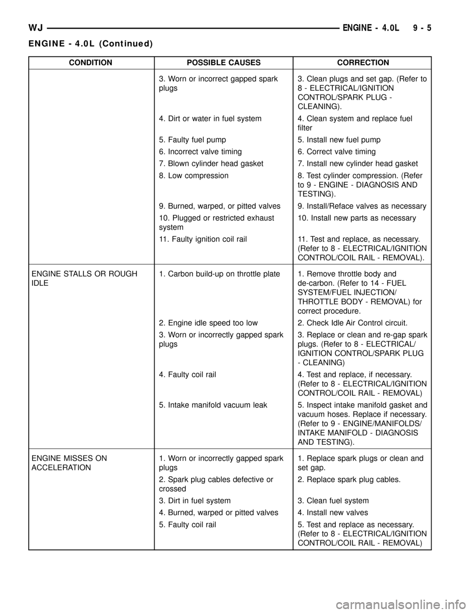
CONDITION POSSIBLE CAUSES CORRECTION
3. Worn or incorrect gapped spark
plugs3. Clean plugs and set gap. (Refer to
8 - ELECTRICAL/IGNITION
CONTROL/SPARK PLUG -
CLEANING).
4. Dirt or water in fuel system 4. Clean system and replace fuel
filter
5. Faulty fuel pump 5. Install new fuel pump
6. Incorrect valve timing 6. Correct valve timing
7. Blown cylinder head gasket 7. Install new cylinder head gasket
8. Low compression 8. Test cylinder compression. (Refer
to 9 - ENGINE - DIAGNOSIS AND
TESTING).
9. Burned, warped, or pitted valves 9. Install/Reface valves as necessary
10. Plugged or restricted exhaust
system10. Install new parts as necessary
11. Faulty ignition coil rail 11. Test and replace, as necessary.
(Refer to 8 - ELECTRICAL/IGNITION
CONTROL/COIL RAIL - REMOVAL).
ENGINE STALLS OR ROUGH
IDLE1. Carbon build-up on throttle plate 1. Remove throttle body and
de-carbon. (Refer to 14 - FUEL
SYSTEM/FUEL INJECTION/
THROTTLE BODY - REMOVAL) for
correct procedure.
2. Engine idle speed too low 2. Check Idle Air Control circuit.
3. Worn or incorrectly gapped spark
plugs3. Replace or clean and re-gap spark
plugs. (Refer to 8 - ELECTRICAL/
IGNITION CONTROL/SPARK PLUG
- CLEANING)
4. Faulty coil rail 4. Test and replace, if necessary.
(Refer to 8 - ELECTRICAL/IGNITION
CONTROL/COIL RAIL - REMOVAL)
5. Intake manifold vacuum leak 5. Inspect intake manifold gasket and
vacuum hoses. Replace if necessary.
(Refer to 9 - ENGINE/MANIFOLDS/
INTAKE MANIFOLD - DIAGNOSIS
AND TESTING).
ENGINE MISSES ON
ACCELERATION1. Worn or incorrectly gapped spark
plugs1. Replace spark plugs or clean and
set gap.
2. Spark plug cables defective or
crossed2. Replace spark plug cables.
3. Dirt in fuel system 3. Clean fuel system
4. Burned, warped or pitted valves 4. Install new valves
5. Faulty coil rail 5. Test and replace as necessary.
(Refer to 8 - ELECTRICAL/IGNITION
CONTROL/COIL RAIL - REMOVAL)
WJENGINE - 4.0L 9 - 5
ENGINE - 4.0L (Continued)
Page 1257 of 2199

WARNING: USE EXTREME CAUTION WHEN THE
ENGINE IS OPERATING. DO NOT STAND IN A
DIRECT LINE WITH THE FAN. DO NOT PUT YOUR
HANDS NEAR THE PULLEYS, BELTS OR FAN. DO
NOT WEAR LOOSE CLOTHING.
(48) Start the engine, inspect for leaks and correct
the fluid levels, as necessary.
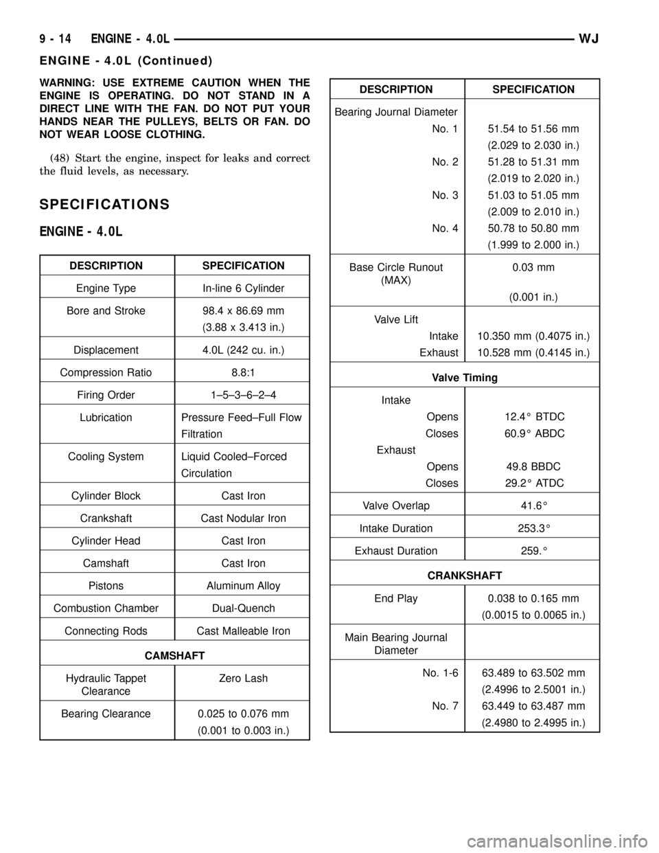
SPECIFICATIONS
ENGINE - 4.0L
DESCRIPTION SPECIFICATION
Engine Type In-line 6 Cylinder
Bore and Stroke 98.4 x 86.69 mm
(3.88 x 3.413 in.)
Displacement 4.0L (242 cu. in.)
Compression Ratio 8.8:1
Firing Order 1±5±3±6±2±4
Lubrication Pressure Feed±Full Flow
Filtration
Cooling System Liquid Cooled±Forced
Circulation
Cylinder Block Cast Iron
Crankshaft Cast Nodular Iron
Cylinder Head Cast Iron
Camshaft Cast Iron
Pistons Aluminum Alloy
Combustion Chamber Dual-Quench
Connecting Rods Cast Malleable Iron
CAMSHAFT
Hydraulic Tappet
ClearanceZero Lash
Bearing Clearance 0.025 to 0.076 mm
(0.001 to 0.003 in.)
DESCRIPTION SPECIFICATION
Bearing Journal Diameter
No. 1 51.54 to 51.56 mm
(2.029 to 2.030 in.)
No. 2 51.28 to 51.31 mm
(2.019 to 2.020 in.)
No. 3 51.03 to 51.05 mm
(2.009 to 2.010 in.)
No. 4 50.78 to 50.80 mm
(1.999 to 2.000 in.)
Base Circle Runout
(MAX)0.03 mm
(0.001 in.)
Valve Lift
Intake 10.350 mm (0.4075 in.)
Exhaust 10.528 mm (0.4145 in.)
Valve Timing
Intake
Opens 12.4É BTDC
Closes 60.9É ABDC
Exhaust
Opens 49.8 BBDC
Closes 29.2É ATDC
Valve Overlap 41.6É
Intake Duration 253.3É
Exhaust Duration 259.É
CRANKSHAFT
End Play 0.038 to 0.165 mm
(0.0015 to 0.0065 in.)
Main Bearing Journal
Diameter
No. 1-6 63.489 to 63.502 mm
(2.4996 to 2.5001 in.)
No. 7 63.449 to 63.487 mm
(2.4980 to 2.4995 in.)
9 - 14 ENGINE - 4.0LWJ
ENGINE - 4.0L (Continued)
Page 1274 of 2199

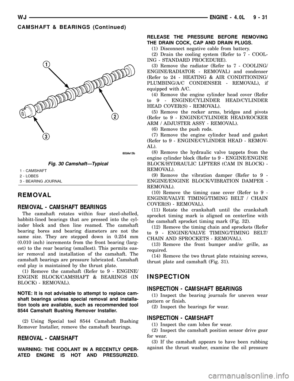
REMOVAL
REMOVAL - CAMSHAFT BEARINGS
The camshaft rotates within four steel-shelled,
babbitt-lined bearings that are pressed into the cyl-
inder block and then line reamed. The camshaft
bearing bores and bearing diameters are not the
same size. They are stepped down in 0.254 mm
(0.010 inch) increments from the front bearing (larg-
est) to the rear bearing (smallest). This permits eas-
ier removal and installation of the camshaft. The
camshaft bearings are pressure lubricated. Camshaft
end play is maintained by the thrust plate.
(1) Remove the camshaft (Refer to 9 - ENGINE/
ENGINE BLOCK/CAMSHAFT & BEARINGS (IN
BLOCK) - REMOVAL).
NOTE: It is not advisable to attempt to replace cam-
shaft bearings unless special removal and installa-
tion tools are available, such as recommended tool
8544 Camshaft Bushing Remover Installer.
(2) Using Special tool 8544 Camshaft Bushing
Remover Installer, remove the camshaft bearings.
REMOVAL - CAMSHAFT
WARNING: THE COOLANT IN A RECENTLY OPER-
ATED ENGINE IS HOT AND PRESSURIZED.RELEASE THE PRESSURE BEFORE REMOVING
THE DRAIN COCK, CAP AND DRAIN PLUGS.
(1) Disconnect negative cable from battery.
(2) Drain the cooling system (Refer to 7 - COOL-
ING - STANDARD PROCEDURE).
(3) Remove the radiator (Refer to 7 - COOLING/
ENGINE/RADIATOR - REMOVAL) and condenser
(Refer to 24 - HEATING & AIR CONDITIONING/
PLUMBING/A/C CONDENSER - REMOVAL), if
equipped with A/C.
(4) Remove the engine cylinder head cover (Refer
to 9 - ENGINE/CYLINDER HEAD/CYLINDER
HEAD COVER(S) - REMOVAL).
(5) Remove the rocker arms, bridges and pivots
(Refer to 9 - ENGINE/CYLINDER HEAD/ROCKER
ARM / ADJUSTER ASSY - REMOVAL).
(6) Remove the push rods.
(7) Remove the engine cylinder head and gasket
(Refer to 9 - ENGINE/CYLINDER HEAD - REMOV-
AL).
(8) Remove the hydraulic valve tappets from the
engine cylinder block (Refer to 9 - ENGINE/ENGINE
BLOCK/HYDRAULIC LIFTERS (CAM IN BLOCK) -
REMOVAL).
(9) Remove the vibration damper (Refer to 9 -
ENGINE/ENGINE BLOCK/VIBRATION DAMPER -
REMOVAL).
(10) Remove the timing case cover (Refer to 9 -
ENGINE/VALVE TIMING/TIMING BELT / CHAIN
COVER(S) - REMOVAL).
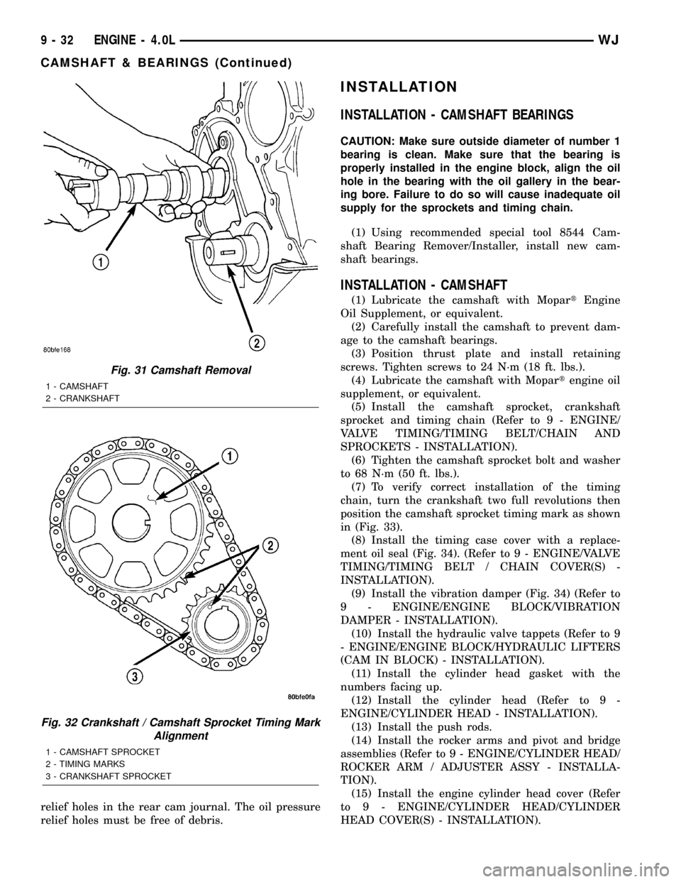
(11) Rotate the crankshaft until the crankshaft
sprocket timing mark is aligned on centerline with
the camshaft sprocket timing mark (Fig. 32).
(12) Remove the timing chain and sprockets (Refer
to 9 - ENGINE/VALVE TIMING/TIMING BELT/
CHAIN AND SPROCKETS - REMOVAL).
(13) Remove the front bumper and/or grille, as
required.
(14) Remove the two thrust plate retaining screws,
thrust plate and camshaft (Fig. 31).
INSPECTION
INSPECTION - CAMSHAFT BEARINGS
(1) Inspect the bearing journals for uneven wear
pattern or finish.
(2) Inspect the bearings for wear.
INSPECTION - CAMSHAFT
(1) Inspect the cam lobes for wear.
(2) Inspect the camshaft position sensor drive gear
for wear.
(3) If the camshaft appears to have been rubbing
against the thrust washer, examine the oil pressure
Fig. 30 CamshaftÐTypical
1 - CAMSHAFT
2 - LOBES
3 - BEARING JOURNAL
WJENGINE - 4.0L 9 - 31
CAMSHAFT & BEARINGS (Continued)
Page 1275 of 2199

relief holes in the rear cam journal. The oil pressure
relief holes must be free of debris.
INSTALLATION
INSTALLATION - CAMSHAFT BEARINGS
CAUTION: Make sure outside diameter of number 1
bearing is clean. Make sure that the bearing is
properly installed in the engine block, align the oil
hole in the bearing with the oil gallery in the bear-
ing bore. Failure to do so will cause inadequate oil
supply for the sprockets and timing chain.
(1) Using recommended special tool 8544 Cam-
shaft Bearing Remover/Installer, install new cam-
shaft bearings.
INSTALLATION - CAMSHAFT
(1) Lubricate the camshaft with MopartEngine
Oil Supplement, or equivalent.
(2) Carefully install the camshaft to prevent dam-
age to the camshaft bearings.
(3) Position thrust plate and install retaining
screws. Tighten screws to 24 N´m (18 ft. lbs.).
(4) Lubricate the camshaft with Mopartengine oil
supplement, or equivalent.
(5) Install the camshaft sprocket, crankshaft
sprocket and timing chain (Refer to 9 - ENGINE/
VALVE TIMING/TIMING BELT/CHAIN AND
SPROCKETS - INSTALLATION).
(6) Tighten the camshaft sprocket bolt and washer
to 68 N´m (50 ft. lbs.).
(7) To verify correct installation of the timing
chain, turn the crankshaft two full revolutions then
position the camshaft sprocket timing mark as shown
in (Fig. 33).
(8) Install the timing case cover with a replace-
ment oil seal (Fig. 34). (Refer to 9 - ENGINE/VALVE
TIMING/TIMING BELT / CHAIN COVER(S) -
INSTALLATION).
(9) Install the vibration damper (Fig. 34) (Refer to
9 - ENGINE/ENGINE BLOCK/VIBRATION
DAMPER - INSTALLATION).
(10) Install the hydraulic valve tappets (Refer to 9
- ENGINE/ENGINE BLOCK/HYDRAULIC LIFTERS
(CAM IN BLOCK) - INSTALLATION).
(11) Install the cylinder head gasket with the
numbers facing up.
(12) Install the cylinder head (Refer to 9 -
ENGINE/CYLINDER HEAD - INSTALLATION).
(13) Install the push rods.
(14) Install the rocker arms and pivot and bridge
assemblies (Refer to 9 - ENGINE/CYLINDER HEAD/
ROCKER ARM / ADJUSTER ASSY - INSTALLA-
TION).
(15) Install the engine cylinder head cover (Refer
to 9 - ENGINE/CYLINDER HEAD/CYLINDER
HEAD COVER(S) - INSTALLATION).
Fig. 31 Camshaft Removal
1 - CAMSHAFT
2 - CRANKSHAFT
Fig. 32 Crankshaft / Camshaft Sprocket Timing Mark
Alignment
1 - CAMSHAFT SPROCKET
2 - TIMING MARKS
3 - CRANKSHAFT SPROCKET
9 - 32 ENGINE - 4.0LWJ
CAMSHAFT & BEARINGS (Continued)