2003 JEEP GRAND CHEROKEE Seat relay
[x] Cancel search: Seat relayPage 1121 of 2199
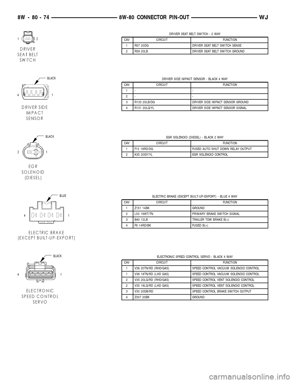
DRIVER SEAT BELT SWITCH-2WAY
CAV CIRCUIT FUNCTION
1 R57 20DG DRIVER SEAT BELT SWITCH SENSE
2 R59 20LB DRIVER SEAT BELT SWITCH GROUND
DRIVER SIDE IMPACT SENSOR - BLACK 4 WAY
CAV CIRCUIT FUNCTION
1- -
2- -
3 R133 20LB/DG DRIVER SIDE IMPACT SENSOR GROUND
4 R131 20LG/YL DRIVER SIDE IMPACT SENSOR SIGNAL
EGR SOLENOID (DIESEL) - BLACK 2 WAY
CAV CIRCUIT FUNCTION
1 F15 18RD/DG FUSED AUTO SHUT DOWN RELAY OUTPUT
2 K35 20GY/YL EGR SOLENOID CONTROL
ELECTRIC BRAKE (EXCEPT BUILT-UP-EXPORT) - BLUE 4 WAY
CAV CIRCUIT FUNCTION
1 Z151 14BK GROUND
2 L50 18WT/TN PRIMARY BRAKE SWITCH SIGNAL
3 B40 12LB TRAILER TOW BRAKE B(+)
4 F9 14RD/BK FUSED B(+)
ELECTRONIC SPEED CONTROL SERVO - BLACK 4 WAY
CAV CIRCUIT FUNCTION
1 V36 20TN/RD (RHD/GAS) SPEED CONTROL VACUUM SOLENOID CONTROL
1 V36 18TN/RD (LHD GAS) SPEED CONTROL VACUUM SOLENOID CONTROL
2 V35 20LG/RD (RHD/GAS) SPEED CONTROL VENT SOLENOID CONTROL
2 V35 18LG/RD (LHD GAS) SPEED CONTROL VENT SOLENOID CONTROL
3 V30 20DB/RD SPEED CONTROL BRAKE SWITCH OUTPUT
4 Z307 20BK GROUND
8W - 80 - 74 8W-80 CONNECTOR PIN-OUTWJ
Page 1133 of 2199
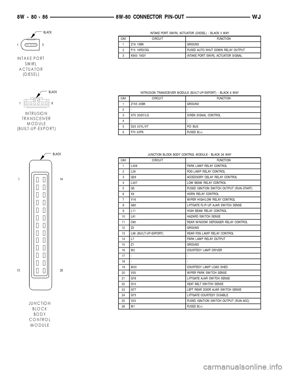
INTAKE PORT SWIRL ACTUATOR (DIESEL) - BLACK 3 WAY
CAV CIRCUIT FUNCTION
1 Z18 18BK GROUND
2 F15 18RD/DG FUSED AUTO SHUT DOWN RELAY OUTPUT
3 K900 18GY INTAKE PORT SWIRL ACTUATOR SIGNAL
INTRUSION TRANSCEIVER MODULE (BUILT-UP-EXPORT) - BLACK 6 WAY
CAV CIRCUIT FUNCTION
1 Z155 20BK GROUND
2- -
3 X75 20GY/LG SIREN SIGNAL CONTROL
4- -
5 D25 20YL/VT PCI BUS
6 F70 20PK FUSED B(+)
JUNCTION BLOCK BODY CONTROL MODULE - BLACK 26 WAY
CAV CIRCUIT FUNCTION
1 L308 PARK LAMP RELAY CONTROL
2 L26 FOG LAMP RELAY CONTROL
3 Q29 ACCESSORY DELAY RELAY CONTROL
4 L307 LOW BEAM RELAY CONTROL
5 G5 FUSED IGNITION SWITCH OUTPUT (RUN-START)
6 X4 HORN RELAY CONTROL
7 V16 WIPER HIGH/LOW RELAY CONTROL
8 G80 LIFTGATE FLIP-UP AJAR SWITCH SENSE
9 L11 HIGH BEAM RELAY CONTROL
10 L91 HAZARD SWITCH SENSE
11 C80 REAR WINDOW DEFOGGER RELAY CONTROL
12 Z2 GROUND
13 L96 (BUILT-UP-EXPORT) REAR FOG LAMP RELAY CONTROL
14 L7 PARK LAMP RELAY OUTPUT
15 Z1 GROUND
16 M2 COURTESY LAMP DRIVER
17 - -
18 - -
19 M20 COURTESY LAMP LOAD SHED
20 V55 WIPER PARK SWITCH SENSE
21 G78 LIFTGATE AJAR SWITCH SENSE
22 G10 SEAT BELT SWITCH SENSE
23 G77 LEFT REAR DOOR AJAR SWITCH SENSE
24 G73 LIFTGATE COURTESY DISABLE
25 V23 FUSED IGNITION SWITCH OUTPUT (RUN-ACC)
26 M1 FUSED B(+)
8W - 80 - 86 8W-80 CONNECTOR PIN-OUTWJ
Page 1166 of 2199
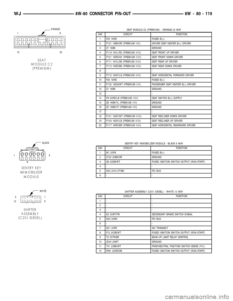
SEAT MODULE C2 (PREMIUM) - ORANGE 20 WAY
CAV CIRCUIT FUNCTION
1 F35 16RD FUSED B(+)
2 P131 16BK/OR (PREMIUM I/III) DRIVER SEAT HEATER B(+) DRIVER
3 Z1 16BK GROUND
4 P119 16YL/RD (PREMIUM II/III) SEAT FRONT UP DRIVER
5 P121 16RD/GY (PREMIUM II/III) SEAT FRONT DOWN DRIVER
6 P111 16YL/DB (PREMIUM II/III) SEAT REAR UP DRIVER
7 P113 16RD/BK (PREMIUM II/III) SEAT REAR DOWN DRIVER
8- -
9 P115 16GY/LG (PREMIUM II/III) SEAT HORIZONTAL FORWARD DRIVER
10 F35 16RD FUSED B(+)
11 P130 16DG/WT (PREMIUM I/III) PASSENGER SEAT HEATER B(+) DRIVER
12 Z1 16BK GROUND
13 - -
14 P9 20RD/LB (PREMIUM II/III) SEAT SWITCH B(+) SUPPLY
15 Z6 16BK/YL (PREMIUM I/III) GROUND
16 Z5 16BK/VT (PREMIUM I/III) GROUND
17 - -
18 P141 16GY/WT (PREMIUM II/III) SEAT RECLINER DOWN DRIVER
19 P143 16GY/LB (PREMIUM II/III) SEAT RECLINER UP DRIVER
20 P117 16RD/BR (PREMIUM II/III) SEAT HORIZONTAL REARWARD DRIVER
SENTRY KEY IMMOBILIZER MODULE - BLACK 6 WAY
CAV CIRCUIT FUNCTION
1 M1 20PK FUSED B(+)
2 Z132 20BK/OR GROUND
3 G5 20DB/WT FUSED IGNITION SWITCH OUTPUT (RUN-START)
4- -
5 D25 20YL/VT/BK PCI BUS
6- -
SHIFTER ASSEMBLY (C201 DIESEL) - WHITE 12 WAY
CAV CIRCUIT FUNCTION
1- -
2- -
3- -
4 K2 20WT/PK SECONDARY BRAKE SWITCH SIGNAL
5 D25 20RD PCI BUS
6- -
7 D21 20PK SCI TRANSMIT
8 F12 20DB/WT FUSED IGNITION SWITCH OUTPUT (RUN-START)
9 T2 20TN/BK BACK-UP LAMP RELAY CONTROL
10 Z234 20WT GROUND
11 T41 20BK/WT PARK/NEUTRAL POSITION SWITCH SENSE (T41)
12 F991 20OR/DB FUSED IGNITION SWITCH OUTPUT (RUN-START)
WJ8W-80 CONNECTOR PIN-OUT 8W - 80 - 119
Page 1184 of 2199
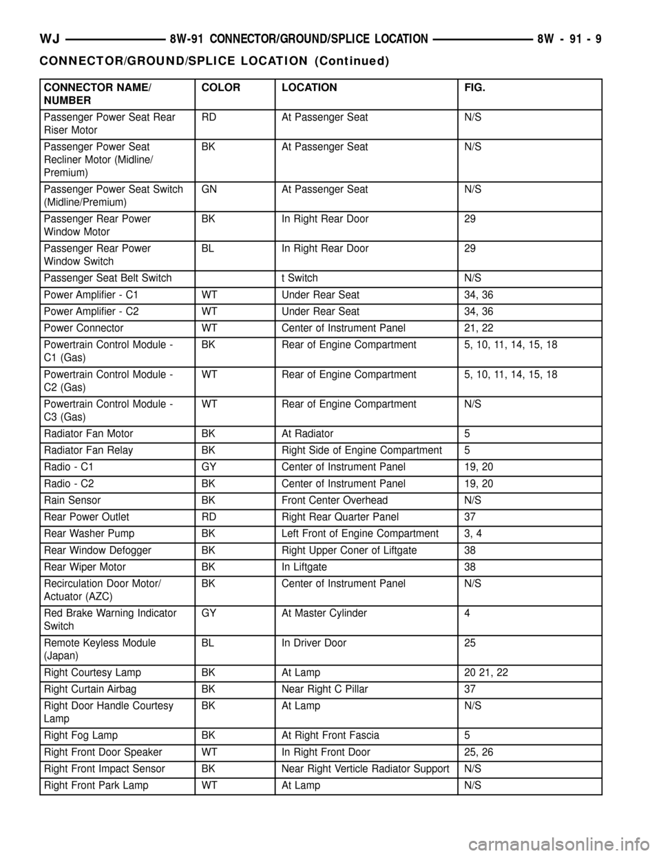
CONNECTOR NAME/
NUMBERCOLOR LOCATION FIG.
Passenger Power Seat Rear
Riser MotorRD At Passenger Seat N/S
Passenger Power Seat
Recliner Motor (Midline/
Premium)BK At Passenger Seat N/S
Passenger Power Seat Switch
(Midline/Premium)GN At Passenger Seat N/S
Passenger Rear Power
Window MotorBK In Right Rear Door 29
Passenger Rear Power
Window SwitchBL In Right Rear Door 29
Passenger Seat Belt Switch t Switch N/S
Power Amplifier - C1 WT Under Rear Seat 34, 36
Power Amplifier - C2 WT Under Rear Seat 34, 36
Power Connector WT Center of Instrument Panel 21, 22
Powertrain Control Module -
C1 (Gas)BK Rear of Engine Compartment 5, 10, 11, 14, 15, 18
Powertrain Control Module -
C2 (Gas)WT Rear of Engine Compartment 5, 10, 11, 14, 15, 18
Powertrain Control Module -
C3 (Gas)WT Rear of Engine Compartment N/S
Radiator Fan Motor BK At Radiator 5
Radiator Fan Relay BK Right Side of Engine Compartment 5
Radio - C1 GY Center of Instrument Panel 19, 20
Radio - C2 BK Center of Instrument Panel 19, 20
Rain Sensor BK Front Center Overhead N/S
Rear Power Outlet RD Right Rear Quarter Panel 37
Rear Washer Pump BK Left Front of Engine Compartment 3, 4
Rear Window Defogger BK Right Upper Coner of Liftgate 38
Rear Wiper Motor BK In Liftgate 38
Recirculation Door Motor/
Actuator (AZC)BK Center of Instrument Panel N/S
Red Brake Warning Indicator
SwitchGY At Master Cylinder 4
Remote Keyless Module
(Japan)BL In Driver Door 25
Right Courtesy Lamp BK At Lamp 20 21, 22
Right Curtain Airbag BK Near Right C Pillar 37
Right Door Handle Courtesy
LampBK At Lamp N/S
Right Fog Lamp BK At Right Front Fascia 5
Right Front Door Speaker WT In Right Front Door 25, 26
Right Front Impact Sensor BK Near Right Verticle Radiator Support N/S
Right Front Park Lamp WT At Lamp N/S
WJ8W-91 CONNECTOR/GROUND/SPLICE LOCATION 8W - 91 - 9
CONNECTOR/GROUND/SPLICE LOCATION (Continued)
Page 1186 of 2199
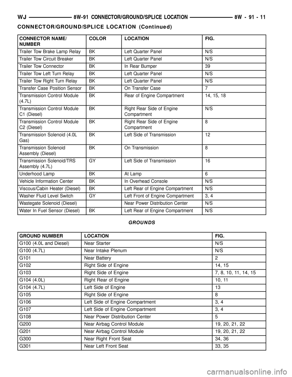
CONNECTOR NAME/
NUMBERCOLOR LOCATION FIG.
Trailer Tow Brake Lamp Relay BK Left Quarter Panel N/S
Trailer Tow Circuit Breaker BK Left Quarter Panel N/S
Trailer Tow Connector BK In Rear Bumper 39
Trailer Tow Left Turn Relay BK Left Quarter Panel N/S
Trailer Tow Right Turn Relay BK Left Quarter Panel N/S
Transfer Case Position Sensor BK On Transfer Case 7
Transmission Control Module
(4.7L)BK Rear of Engine Compartment 14, 15, 18
Transmission Control Module
C1 (Diesel)BK Right Rear Side of Engine
CompartmentN/S
Transmission Control Module
C2 (Diesel)BK Right Rear Side of Engine
Compartment8
Transmission Solenoid (4.0L
Gas)BK Left Side of Transmission 12
Transmission Solenoid
Assembly (Diesel)BK On Transmission 8
Transmission Solenoid/TRS
Assembly (4.7L)GY Left Side of Transmission 16
Underhood Lamp BK At Lamp 6
Vehicle Information Center BK In Overhead Console N/S
Viscous/Cabin Heater (Diesel) BK Left Rear of Engine Compartment N/S
Washer Fluid Level Switch GY Left Front of Engine Compartment 3, 4
Wastegate Solenoid (Diesel) Near Power Distribution Center N/S
Water In Fuel Sensor (Diesel) BK Left Rear of Engine Compartment N/S
GROUNDS
GROUND NUMBER LOCATION FIG.
G100 (4.0L and Diesel) Near Starter N/S
G100 (4.7L) Near Intake Plenum N/S
G101 Near Battery 2
G102 Right Side of Engine 14, 15
G103 Right Side of Engine 7, 8, 10, 11, 14, 15
G104 (4.0L) Right Rear of Engine 10, 11
G104 (4.7L) Left Side of Engine 13
G105 Right Side of Engine 8
G106 Left Side of Engine Compartment 3, 4
G107 Left Side of Engine Compartment 3, 4
G108 Near Power Distribution Center 5
G200 Near Airbag Control Module 19, 20, 21, 22
G201 Near Airbag Control Module 19, 20, 21, 22
G300 Near Right Front Seat 34, 36
G301 Near Left Front Seat 33, 35
WJ8W-91 CONNECTOR/GROUND/SPLICE LOCATION 8W - 91 - 11
CONNECTOR/GROUND/SPLICE LOCATION (Continued)
Page 1240 of 2199

ground at all times. If not OK, repair the open
ground circuit to ground as required.
REMOVAL
(1) Disconnect and isolate the battery negative
cable.
(2) Remove the steering column opening cover
from the instrument panel. Refer toSteering Col-
umn Opening Coverin Body for the procedure.
(3) The power outlet / cigar lighter relay is located
on the left side of the combination flasher in the
junction block.
(4) Remove the power outlet / cigar lighter relay
from the junction block.
INSTALLATION
(1) Position the power outlet / cigar lighter relay in
the proper receptacle in the junction block.
(2) Align the power outlet / cigar lighter relay ter-
minals with the terminal cavities in the junction
block receptacle.
(3) Push in firmly on the power outlet / cigar
lighter relay until the terminals are fully seated in
the terminal cavities in the junction block receptacle.
(4) Install the steering column opening cover onto
the instrument panel. Refer toSteering Column
Opening Coverin Body for the procedure.
(5) Reconnect the battery negative cable.
IOD WIRE HARNESS
CONNECTOR
DESCRIPTION
All vehicles are equipped with an Ignition-Off
Draw (IOD) connector that is located in a molded
connector receptacle on the lower rear surface of the
Junction Block (JB) housing (Fig. 17). The JB is con-
cealed above the molded plastic instrument panel
fuse cover. Integral latches molded into the fuse
cover secure it the JB, the Body Control Module
(BCM) and the 16-way data link connector tab of the
instrument panel steering column support bracket.
The fuse cover can be pulled downward to disengage
the latches and provide service access to all of the
fuses, relays and wire harness connectors of the JB.
Refer toInstrument Panel Fuse Coverin the
index of this service manual for the location of addi-
tional service information covering the fuse cover.
OPERATION
The term ignition-off draw identifies a normal con-
dition where power is being drained from the battery
with the ignition switch in the Off position. The IOD
connector feeds the memory and sleep mode func-
tions for some of the electronic modules in the vehicleas well as various other accessories that require bat-
tery current when the ignition switch is in the Off
position, including the clock.
The IOD connector can be used by the vehicle
owner as a convenient means of reducing battery
depletion when a vehicle is to be stored for periods
not to exceed about twenty days (short-term storage).
Simply disconnect the IOD connector from the JB
receptacle. However, it must be remembered that dis-
connecting the IOD connector will not eliminate IOD,
but only reduce this normal condition. When a vehi-
cle will not be used for more than twenty days, but
less than thirty days, remove the IOD fuse from the
Power Distribution Center (PDC). If a vehicle will be
stored for more than about thirty days, the battery
negative cable should be disconnected to eliminate
normal IOD; and, the battery should be tested and
recharged at regular intervals during the vehicle
storage period to prevent the battery from becoming
discharged or damaged. Refer toIgnition-Off Draw
Fig. 17 Ignition-Off Draw Connector
1 - SNAP CLIPS
2 - SCREW
3 - CONNECTOR
4 - LEFT BODY WIRE HARNESS
5 - IOD CONNECTOR
6 - FUSED B+ CONNECTOR
7 - RIGHT BODY WIRE HARNESS
8 - SCREW
9 - CONNECTOR
10 - JUNCTION BLOCK
WJ8W-97 POWER DISTRIBUTION 8W - 97 - 15
POWER OUTLET RELAY (Continued)
Page 1311 of 2199
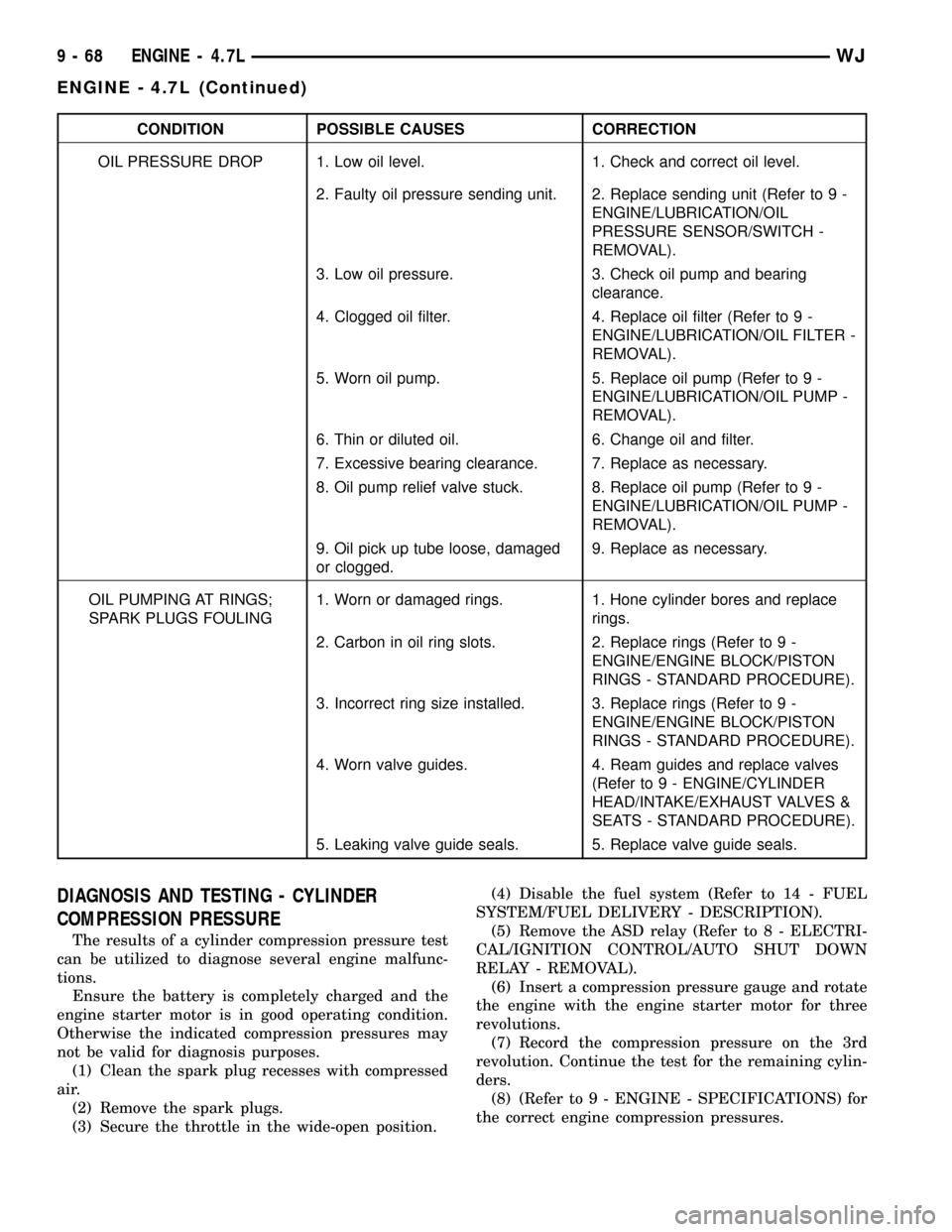
CONDITION POSSIBLE CAUSES CORRECTION
OIL PRESSURE DROP 1. Low oil level. 1. Check and correct oil level.
2. Faulty oil pressure sending unit. 2. Replace sending unit (Refer to 9 -
ENGINE/LUBRICATION/OIL
PRESSURE SENSOR/SWITCH -
REMOVAL).
3. Low oil pressure. 3. Check oil pump and bearing
clearance.
4. Clogged oil filter. 4. Replace oil filter (Refer to 9 -
ENGINE/LUBRICATION/OIL FILTER -
REMOVAL).
5. Worn oil pump. 5. Replace oil pump (Refer to 9 -
ENGINE/LUBRICATION/OIL PUMP -
REMOVAL).
6. Thin or diluted oil. 6. Change oil and filter.
7. Excessive bearing clearance. 7. Replace as necessary.
8. Oil pump relief valve stuck. 8. Replace oil pump (Refer to 9 -
ENGINE/LUBRICATION/OIL PUMP -
REMOVAL).
9. Oil pick up tube loose, damaged
or clogged.9. Replace as necessary.
OIL PUMPING AT RINGS;
SPARK PLUGS FOULING1. Worn or damaged rings. 1. Hone cylinder bores and replace
rings.
2. Carbon in oil ring slots. 2. Replace rings (Refer to 9 -
ENGINE/ENGINE BLOCK/PISTON
RINGS - STANDARD PROCEDURE).
3. Incorrect ring size installed. 3. Replace rings (Refer to 9 -
ENGINE/ENGINE BLOCK/PISTON
RINGS - STANDARD PROCEDURE).
4. Worn valve guides. 4. Ream guides and replace valves
(Refer to 9 - ENGINE/CYLINDER
HEAD/INTAKE/EXHAUST VALVES &
SEATS - STANDARD PROCEDURE).
5. Leaking valve guide seals. 5. Replace valve guide seals.
DIAGNOSIS AND TESTING - CYLINDER
COMPRESSION PRESSURE
The results of a cylinder compression pressure test
can be utilized to diagnose several engine malfunc-
tions.
Ensure the battery is completely charged and the
engine starter motor is in good operating condition.
Otherwise the indicated compression pressures may
not be valid for diagnosis purposes.
(1) Clean the spark plug recesses with compressed
air.
(2) Remove the spark plugs.
(3) Secure the throttle in the wide-open position.(4) Disable the fuel system (Refer to 14 - FUEL
SYSTEM/FUEL DELIVERY - DESCRIPTION).
(5) Remove the ASD relay (Refer to 8 - ELECTRI-
CAL/IGNITION CONTROL/AUTO SHUT DOWN
RELAY - REMOVAL).
(6) Insert a compression pressure gauge and rotate
the engine with the engine starter motor for three
revolutions.
(7) Record the compression pressure on the 3rd
revolution. Continue the test for the remaining cylin-
ders.
(8) (Refer to 9 - ENGINE - SPECIFICATIONS) for
the correct engine compression pressures.
9 - 68 ENGINE - 4.7LWJ
ENGINE - 4.7L (Continued)
Page 1789 of 2199

(8) Install the transmission in the vehicle.
(9) Fill the transmission with the recommended
fluid.
TRANSMISSION CONTROL
RELAY
DESCRIPTION
The relay is supplied fused B+ voltage, energized
by the TCM, and is used to supply power to the sole-
noid pack when the transmission is in normal oper-
ating mode.
OPERATION
When the relay is ªoffº, no power is supplied to the
solenoid pack and the transmission is in ªlimp-inº
mode. After a controller reset, the TCM energizes the
relay. Prior to this, the TCM verifies that the con-
tacts are open by checking for no voltage at the
switched battery terminals. After this is verified, the
voltage at the solenoid pack pressure switches is
checked. After the relay is energized, the TCM mon-
itors the terminals to verify that the voltage is
greater than 3 volts.
TRANSMISSION RANGE
SENSOR
DESCRIPTION
The Transmission Range Sensor (TRS) is part of
the solenoid module, which is mounted to the top of
the valve body inside the transmission.
The Transmission Range Sensor (TRS) has five
switch contact pins that:
²Determine shift lever position
²Supply ground to the Starter Relay in Park and
Neutral only.
²Supply +12 V to the backup lamps in Reverse
only.
The TRS also has an integrated temperature sen-
sor (thermistor) that communicates transmission
temperature to the TCM and PCM.
OPERATION
The Transmission Range Sensor (TRS) communi-
cates shift lever position to the TCM as a combina-
tion of open and closed switches. Each shift lever
position has an assigned combination of switch states
(open/closed) that the TCM receives from four sense
circuits. The TCM interprets this information and
determines the appropriate transmission gear posi-
tion and shift schedule.
There are many possible combinations of open and
closed switches (codes). Seven of these possible codes
are related to gear position and five are recognized
as ªbetween gearº codes. This results in many codes
which shouldnever occur. These are called
ªinvalidº codes. An invalid code will result in a DTC,
and the TCM will then determine the shift lever
position based on pressure switch data. This allows
reasonably normal transmission operation with a
TRS failure.
GEAR C5 C4 C3 C2 C1
ParkCL OP OP CL CL
Temp 1CL OP OP CL OP
ReverseOP OP OP CL OP
Temp 2OP OP CL CL OP
Neutral 1OP OP CL CL CL
Neutral 2OP CL CL CL CL
Temp 3OP CL CL CL OP
DriveOP CL CL OP OP
Temp 4OP CL OP OP OP
Manual 2CL CL OP OP OP
Temp 5CL OP OP OP OP
Manual 1CL OP CL OP OP
Fig. 117 Checking Torque Converter Seating-Typical
1 - SCALE
2 - STRAIGHTEDGE
21 - 270 AUTOMATIC TRANSMISSION - 545RFEWJ
TORQUE CONVERTER (Continued)