2003 JEEP GRAND CHEROKEE Radiator Lower Hose
[x] Cancel search: Radiator Lower HosePage 1389 of 2199

TIMING BELT / CHAIN
COVER(S)
REMOVAL
(1) Disconnect the battery negative cable.
(2) Drain cooling system (Refer to 7 - COOLING -
STANDARD PROCEDURE).
(3) Disconnect both heater hoses at timing cover.
(4) Disconnect lower radiator hose at engine.
(5) Remove crankshaft damper (Refer to 9 -
ENGINE/ENGINE BLOCK/VIBRATION DAMPER -
REMOVAL).
(6) Remove accessory drive belt tensioner assembly
(Fig. 117).
(7) Remove the generator and A/C compressor.
(8) Remove cover and gasket (Fig. 118).
INSTALLATION
(1) Clean timing chain cover and block surface.
Inspect cover gasket and replace as necessary.
(2) Install cover and gasket. Tighten fasteners in
sequence as shown in (Fig. 119) to 54 N´m (40 ft.
lbs.).
(3) Install the A/C compressor and generator.(4) Install crankshaft damper (Refer to 9 -
ENGINE/ENGINE BLOCK/VIBRATION DAMPER -
INSTALLATION).
(5) Install accessory drive belt tensioner assembly.
Tighten fastener to 54 N´m (40 ft. lbs.).
(6) Install lower radiator hose.
(7) Install both heater hoses.
(8) Fill cooling system (Refer to 7 - COOLING -
STANDARD PROCEDURE).
(9) Connect the battery negative cable.
Fig. 117 Accessory Drive Belt Tensioner
1 - TENSIONER ASSEMBLY
2 - FASTENER TENSIONER TO FRONT COVER
Fig. 118 Timing Chain Cover Fasteners
Fig. 119 Timing Chain Cover Fasteners
9 - 146 ENGINE - 4.7LWJ
Page 1513 of 2199

SPECIAL TOOLS
POWER STEERING PUMP
FLUID COOLER
DESCRIPTION
4.7L models of this vehicle are equipped with a
cooler for the power steering system fluid. The power
steering fluid cooler is located at the front of the
vehicle. It is mounted to the radiator support just
forward of the air-conditioning condenser and just
rearward of the front fascia (Fig. 6). The cooler is
positioned so it is in the air flow through the front
fascia of the vehicle.
REMOVAL
(1) Disconnect negative battery cable at battery.
(2) Drain the power steering fluid out of the reser-
voir.
(3) Remove the front fascia grille assembly,(Refer
to 13 - FRAMES & BUMPERS/BUMPERS/FRONT
FASCIA - REMOVAL).
(4) Remove the grille opening reinforcement panel
(5) Place a drain pan under the cooler.
(6) Disconnect the lower hose at cooler (Fig. 6).
(7) Disconnect the upper hose at cooler (Fig. 6).
(8) Remove the three cooler mounting bolts (Fig.
6).
(9) Remove the cooler from the vehicle.
Analyzer Set, Power Steering Flow/Pressure 6815
Adapters, Power Steering Flow/Pressure Tester
6893
4.7L HYDRAULIC POWER STEERING TEST
ADAPTER KIT - 8630
Puller C-4333
Installer, Power Steering Pulley C-4063B
Fig. 6 POWER STEERING FLUID COOLER
1 - POWER STEERING COOLER
2 - POWER STEERING COOLER LINES CLIP
19 - 36 PUMPWJ
PUMP (Continued)
Page 1517 of 2199

(5) Disconnect the rubber hose from the power
steering reservoir (Fig. 12).
(6) Remove the hose from the vehicle.
REMOVAL - 3/8(GEAR OUTLET HOSE
(1) Drain the power steering fluid from the reser-
voir.
(2) Remove the air box,(Refer to 9 - ENGINE/AIR
INTAKE SYSTEM/AIR CLEANER HOUSING -
REMOVAL).
(3) Raise and support the vehicle.
(4) Disconnect the rubber hose from the steering
cooler inlet tube (Fig. 11).
(5) Disconnect the metal tube from the power
steering gear (Fig. 11).
(6) Remove the hose from the vehicle.
REMOVAL - INLET COOLER HOSE
(1) Disconnect negative battery cable at battery.
(2) Drain the power steering fluid out of the reser-
voir.
(3) Remove the air box,(Refer to 9 - ENGINE/AIR
INTAKE SYSTEM/AIR CLEANER HOUSING -
REMOVAL).
(4) Remove the front fascia grille assembly,(Refer
to 13 - FRAMES & BUMPERS/BUMPERS/FRONT
FASCIA - REMOVAL).
(5) Remove the grille opening reinforcement panel
(6) Place a drain pan under the cooler.
(7) Disconnect the lower hose at cooler (Fig. 6).
(8) Disconnect the cooler hose at the gear.
(9) Remove the bracket holding the cooler hoses
(Fig. 13).
(10) Remove the cooler hose from the vehicle.
REMOVAL - OUTLET COOLER HOSE
(1) Disconnect negative battery cable at battery.
(2) Drain the power steering fluid out of the reser-
voir.
(3) Remove the air box,(Refer to 9 - ENGINE/AIR
INTAKE SYSTEM/AIR CLEANER HOUSING -
REMOVAL).
(4) Remove the front fascia grille assembly,(Refer
to 13 - FRAMES & BUMPERS/BUMPERS/FRONT
FASCIA - REMOVAL).
(5) Remove the grille opening reinforcement panel
(6) Place a drain pan under the cooler.
(7) Disconnect the upper hose at cooler (Fig. 6).
(8) Disconnect the cooler hose at the reservoir.
(9) Remove the bracket holding the cooler hoses
(Fig. 13).
(10) Remove the cooler hose from the vehicle.
INSTALLATION
INSTALLATION - 1/2(PRESSURE HOSE
NOTE: Lubrication and a new o-ring must be used
when reinstalling.
(1) Install the hoses to the vehicle.
(2) Reconnect the high pressure hose to the power
steering pump (Fig. 8) Tighten the hose to 22.5 N´m
(17 ft.lbs.).
(3) Reconnect the high pressure hose to the
hydraulic fan motor (Fig. 8) Tighten the hose to 22.5
N´m (17 ft.lbs.).
(4) Install the hose to the clipped position on the
fan shroud.
(5) Install the metal skid plate.
(6) Install the air box,(Refer to 9 - ENGINE/AIR
INTAKE SYSTEM/AIR CLEANER HOUSING -
INSTALLATION).
(7) Refill the power steering fluid and bleed the
system,(Refer to 19 - STEERING/PUMP - STAN-
DARD PROCEDURE).
INSTALLATION - 1/2(RETURN HOSE
(1) Install the hoses to the vehicle.
(2) Reconnect the rubber return hose to the power
steering reservoir (Fig. 9) Tighten the hose clamp.
(3) Reconnect the rubber return hose to the
hydraulic fan motor (Fig. 9) Tighten the hose.
(4) Install the metal skid plate.
(5) Install the air box,(Refer to 9 - ENGINE/AIR
INTAKE SYSTEM/AIR CLEANER HOUSING -
INSTALLATION).
(6) Refill the power steering fluid and bleed the
system,(Refer to 19 - STEERING/PUMP - STAN-
DARD PROCEDURE).
Fig. 13 COOLER HOSES MOUNTING BRACKET
1 - RADIATOR
2 - COOLER HOSES MOUNTING BRACKET
2 - COOLER HOSE
19 - 40 PUMPWJ
HOSES - 4.7L (Continued)
Page 2078 of 2199

HEATING & AIR CONDITIONING
TABLE OF CONTENTS
page page
HEATING & AIR CONDITIONING
DESCRIPTION
DESCRIPTION - COOLING SYSTEM
REQUIREMENTS.......................1
DESCRIPTION - HEATER AND AIR
CONDITIONER........................1
DESCRIPTION - REFRIGERANT SYSTEM
SERVICE PORT........................1
OPERATION
OPERATION - HEATER AND AIR
CONDITIONER........................2
OPERATION - REFRIGERANT SYSTEM
SERVICE PORT........................2DIAGNOSIS AND TESTING
DIAGNOSIS AND TESTING - A/C
PERFORMANCE.......................2
DIAGNOSIS AND TESTING - HEATER
PERFORMANCE.......................6
STANDARD PROCEDURE - DIODE
REPLACEMENT.......................6
SPECIFICATIONS
A/C APPLICATION TABLE................7
TORQUE SPECIFICATIONS..............8
CONTROLS.............................9
DISTRIBUTION..........................36
PLUMBING.............................51
HEATING & AIR
CONDITIONING
DESCRIPTION
DESCRIPTION - COOLING SYSTEM
REQUIREMENTS
To maintain the performance level of the heating-
air conditioning system, the engine cooling system
must be properly maintained. The use of a bug
screen is not recommended. Any obstructions in front
of the radiator or condenser will reduce the perfor-
mance of the air conditioning and engine cooling sys-
tems.
The engine cooling system includes the heater core
and the heater hoses. Refer to Cooling for more infor-
mation before opening, or attempting any service to
the engine cooling system.
DESCRIPTION - HEATER AND AIR
CONDITIONER
A manual temperature control type heating-air
conditioning system is standard factory-installed
equipment on this model. An electronically controlled
Automatic Zone Control (AZC) type heating-air con-
ditioning system is an available factory-installed
option.
All vehicles are equipped with a common HVAC
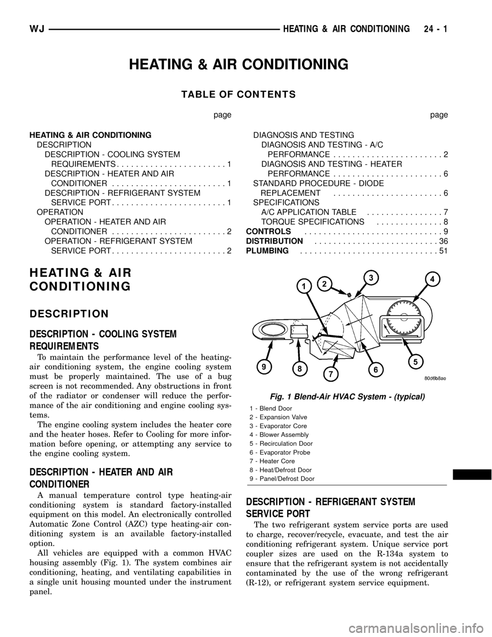
housing assembly (Fig. 1). The system combines air
conditioning, heating, and ventilating capabilities in
a single unit housing mounted under the instrument
panel.DESCRIPTION - REFRIGERANT SYSTEM
SERVICE PORT
The two refrigerant system service ports are used
to charge, recover/recycle, evacuate, and test the air
conditioning refrigerant system. Unique service port
coupler sizes are used on the R-134a system to
ensure that the refrigerant system is not accidentally
contaminated by the use of the wrong refrigerant
(R-12), or refrigerant system service equipment.
Fig. 1 Blend-Air HVAC System - (typical)
1 - Blend Door
2 - Expansion Valve
3 - Evaporator Core
4 - Blower Assembly
5 - Recirculation Door
6 - Evaporator Probe
7 - Heater Core
8 - Heat/Defrost Door
9 - Panel/Defrost Door
WJHEATING & AIR CONDITIONING 24 - 1
Page 2083 of 2199

DIAGNOSIS AND TESTING - HEATER
PERFORMANCE
Before performing the following tests, refer to Cool-
ing for the procedures to check the radiator coolant
level, serpentine drive belt tension, radiator air flow
and the radiator fan operation. Also be certain that
the accessory vacuum supply line is connected at the
engine intake manifold for the manual temperature
control system.
MAXIMUM HEATER OUTPUT
Engine coolant is delivered to the heater core
through two heater hoses. With the engine idling at
normal operating temperature, set the temperature
control knob in the full hot position, the mode control
switch knob in the floor heat position, and the blower
motor switch knob in the highest speed position.
Using a test thermometer, check the temperature of
the air being discharged at the HVAC housing floor
outlets. Compare the test thermometer reading to the
Temperature Reference chart.
Temperature Reference
Ambient Air Temperature15.5É C
(60É F)21.1É C
(70É F)26.6É C
(80É F)32.2É C
(90É F)
Minimum Air Temperature at
Floor Outlet62.2É C
(144É F)63.8É C
(147É F)65.5É C
(150É F)67.2É C
(153É F)
If the floor outlet air temperature is too low, refer
to Cooling to check the engine coolant temperature
specifications. Both of the heater hoses should be hot
to the touch. The coolant return heater hose should
be slightly cooler than the coolant supply heater
hose. If the return hose is much cooler than the sup-
ply hose, locate and repair the engine coolant flow
obstruction in the cooling system. Refer to Cooling
for the procedures.
OBSTRUCTED COOLANT FLOW
Possible locations or causes of obstructed coolant
flow:
²Pinched or kinked heater hoses.
²Improper heater hose routing.
²Plugged heater hoses or supply and return ports
at the cooling system connections.
²A plugged heater core.
If proper coolant flow through the cooling system is
verified, and heater outlet air temperature is still
low, a mechanical problem may exist.
MECHANICAL PROBLEMS
Possible locations or causes of insufficient heat:
²An obstructed cowl air intake.
²Obstructed heater system outlets.
²A blend door not functioning properly.
TEMPERATURE CONTROL
If the heater outlet air temperature cannot be
adjusted with the temperature control knob(s) on the
A/C Heater control panel, the following could require
service:
²The A/C heater control.
²The blend door actuator(s).
²The wire harness circuits for the A/C heater con-
trol or the blend door actuator(s).²The blend door(s).
²Improper engine coolant temperature.
STANDARD PROCEDURE - DIODE
REPLACEMENT
(1) Disconnect and isolate the negative battery
cable.
(2) Locate the diode in the harness, and remove
the protective covering.
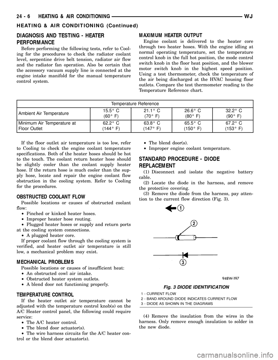
(3) Remove the diode from the harness, pay atten-
tion to the current flow direction (Fig. 3).
(4) Remove the insulation from the wires in the
harness. Only remove enough insulation to solder in
the new diode.
Fig. 3 DIODE IDENTIFICATION
1 - CURRENT FLOW
2 - BAND AROUND DIODE INDICATES CURRENT FLOW
3 - DIODE AS SHOWN IN THE DIAGRAMS
24 - 6 HEATING & AIR CONDITIONINGWJ
HEATING & AIR CONDITIONING (Continued)