2003 JEEP GRAND CHEROKEE Antenna
[x] Cancel search: AntennaPage 1055 of 2199

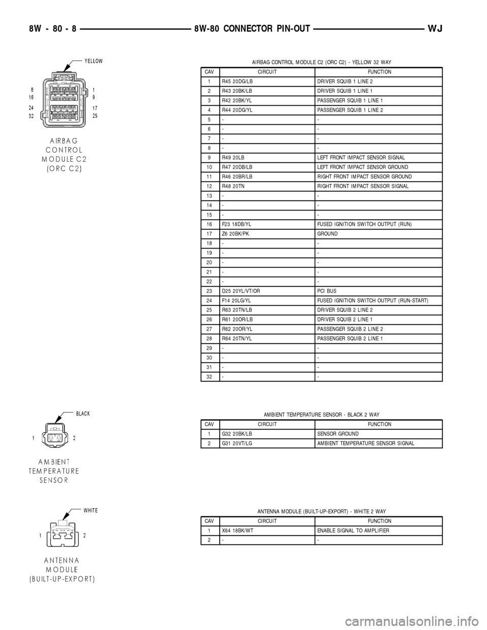
AIRBAG CONTROL MODULE C2 (ORC C2) - YELLOW 32 WAY
CAV CIRCUIT FUNCTION
1 R45 20DG/LB DRIVER SQUIB 1 LINE 2
2 R43 20BK/LB DRIVER SQUIB 1 LINE 1
3 R42 20BK/YL PASSENGER SQUIB 1 LINE 1
4 R44 20DG/YL PASSENGER SQUIB 1 LINE 2
5- -
6- -
7- -
8- -
9 R49 20LB LEFT FRONT IMPACT SENSOR SIGNAL
10 R47 20DB/LB LEFT FRONT IMPACT SENSOR GROUND
11 R46 20BR/LB RIGHT FRONT IMPACT SENSOR GROUND
12 R48 20TN RIGHT FRONT IMPACT SENSOR SIGNAL
13 - -
14 - -
15 - -
16 F23 18DB/YL FUSED IGNITION SWITCH OUTPUT (RUN)
17 Z6 20BK/PK GROUND
18 - -
19 - -
20 - -
21 - -
22 - -
23 D25 20YL/VT/OR PCI BUS
24 F14 20LG/YL FUSED IGNITION SWITCH OUTPUT (RUN-START)
25 R63 20TN/LB DRIVER SQUIB 2 LINE 2
26 R61 20OR/LB DRIVER SQUIB 2 LINE 1
27 R62 20OR/YL PASSENGER SQUIB 2 LINE 2
28 R64 20TN/YL PASSENGER SQUIB 2 LINE 1
29 - -
30 - -
31 - -
32 - -
AMBIENT TEMPERATURE SENSOR - BLACK 2 WAY
CAV CIRCUIT FUNCTION
1 G32 20BK/LB SENSOR GROUND
2 G31 20VT/LG AMBIENT TEMPERATURE SENSOR SIGNAL
ANTENNA MODULE (BUILT-UP-EXPORT) - WHITE 2 WAY
CAV CIRCUIT FUNCTION
1 X64 18BK/WT ENABLE SIGNAL TO AMPLIFIER
2- -
8W - 80 - 8 8W-80 CONNECTOR PIN-OUTWJ
Page 1160 of 2199

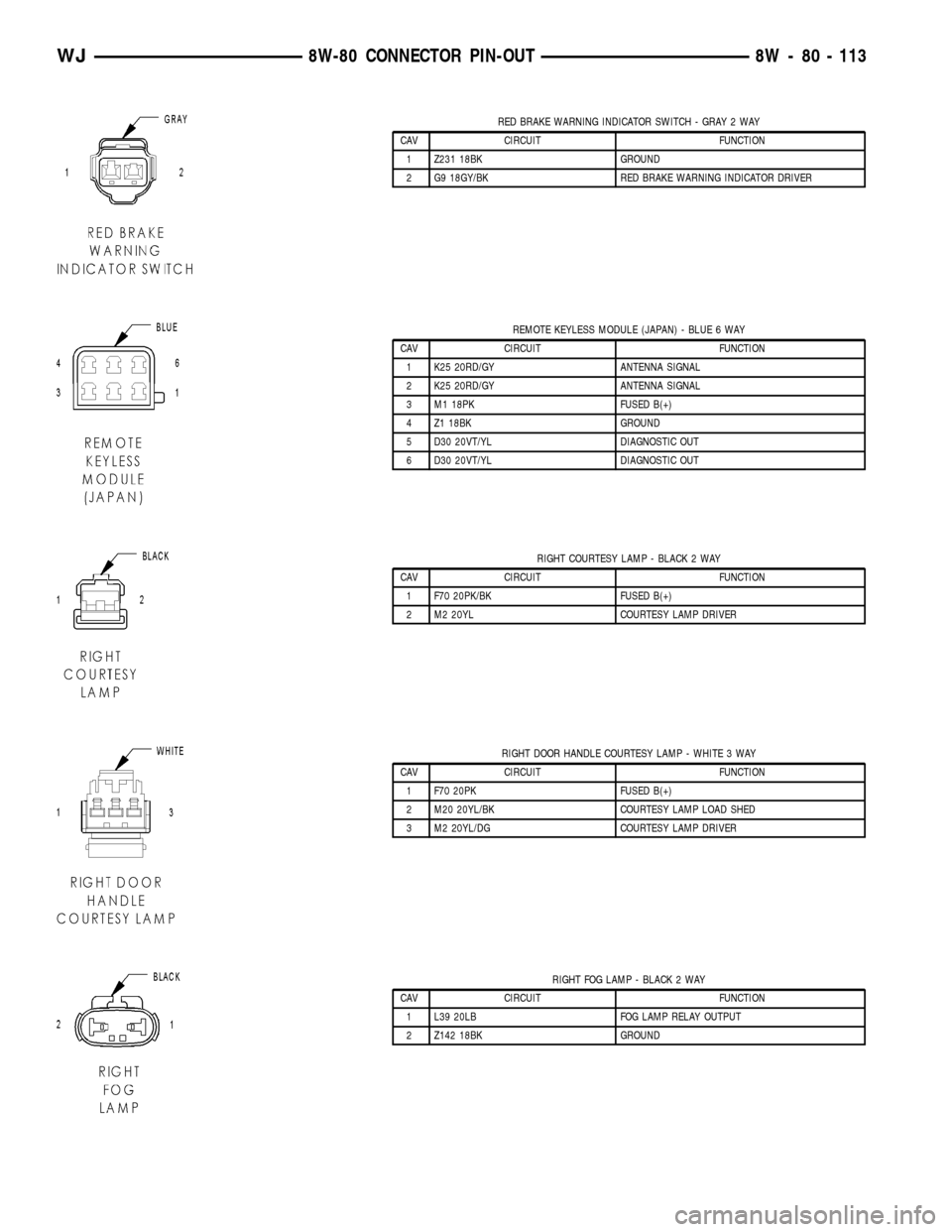
RED BRAKE WARNING INDICATOR SWITCH - GRAY 2 WAY
CAV CIRCUIT FUNCTION
1 Z231 18BK GROUND
2 G9 18GY/BK RED BRAKE WARNING INDICATOR DRIVER
REMOTE KEYLESS MODULE (JAPAN) - BLUE 6 WAY
CAV CIRCUIT FUNCTION
1 K25 20RD/GY ANTENNA SIGNAL
2 K25 20RD/GY ANTENNA SIGNAL
3 M1 18PK FUSED B(+)
4 Z1 18BK GROUND
5 D30 20VT/YL DIAGNOSTIC OUT
6 D30 20VT/YL DIAGNOSTIC OUT
RIGHT COURTESY LAMP - BLACK 2 WAY
CAV CIRCUIT FUNCTION
1 F70 20PK/BK FUSED B(+)
2 M2 20YL COURTESY LAMP DRIVER
RIGHT DOOR HANDLE COURTESY LAMP - WHITE 3 WAY
CAV CIRCUIT FUNCTION
1 F70 20PK FUSED B(+)
2 M20 20YL/BK COURTESY LAMP LOAD SHED
3 M2 20YL/DG COURTESY LAMP DRIVER
RIGHT FOG LAMP - BLACK 2 WAY
CAV CIRCUIT FUNCTION
1 L39 20LB FOG LAMP RELAY OUTPUT
2 Z142 18BK GROUND
WJ8W-80 CONNECTOR PIN-OUT 8W - 80 - 113
Page 1176 of 2199

8W-91 CONNECTOR/GROUND/SPLICE LOCATION
TABLE OF CONTENTS
page
CONNECTOR/GROUND/SPLICE LOCATION
DESCRIPTION..........................1
CONNECTOR/GROUND/SPLICE
LOCATION
DESCRIPTION
This section provides illustrations identifying con-
nector, ground, and splice locations in the vehicle.Connector, ground, and splice indexes are provided.
Use the wiring diagrams in each section for connec-
tor, ground, and splice identification. Refer to the
appropriate index for the proper figure number. For
items that are not shown in this section N/S is placed
in the Fig. column.
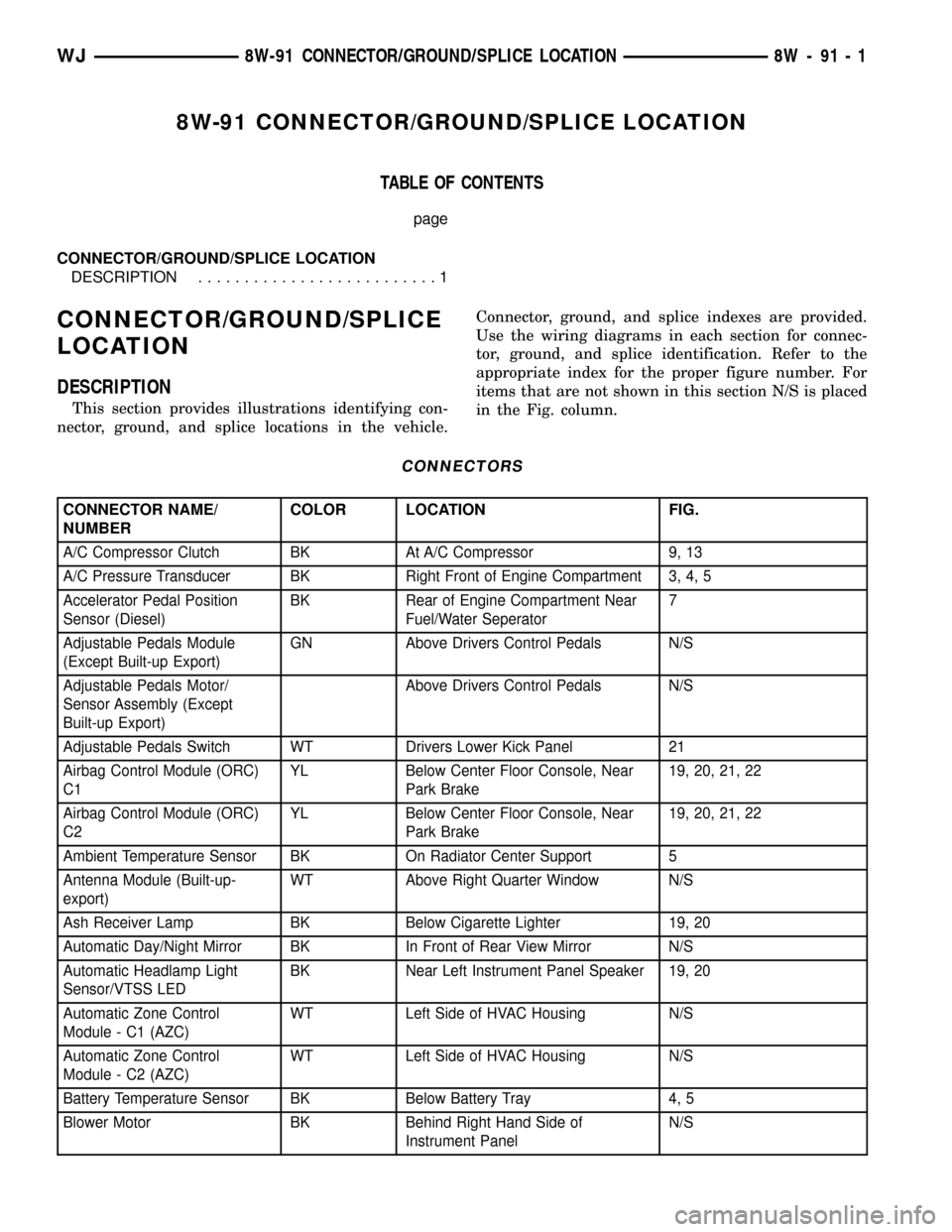
CONNECTORS
CONNECTOR NAME/
NUMBERCOLOR LOCATION FIG.
A/C Compressor Clutch BK At A/C Compressor 9, 13
A/C Pressure Transducer BK Right Front of Engine Compartment 3, 4, 5
Accelerator Pedal Position
Sensor (Diesel)BK Rear of Engine Compartment Near
Fuel/Water Seperator7
Adjustable Pedals Module
(Except Built-up Export)GN Above Drivers Control Pedals N/S
Adjustable Pedals Motor/
Sensor Assembly (Except
Built-up Export)Above Drivers Control Pedals N/S
Adjustable Pedals Switch WT Drivers Lower Kick Panel 21
Airbag Control Module (ORC)
C1YL Below Center Floor Console, Near
Park Brake19, 20, 21, 22
Airbag Control Module (ORC)
C2YL Below Center Floor Console, Near
Park Brake19, 20, 21, 22
Ambient Temperature Sensor BK On Radiator Center Support 5
Antenna Module (Built-up-
export)WT Above Right Quarter Window N/S
Ash Receiver Lamp BK Below Cigarette Lighter 19, 20
Automatic Day/Night Mirror BK In Front of Rear View Mirror N/S
Automatic Headlamp Light
Sensor/VTSS LEDBK Near Left Instrument Panel Speaker 19, 20
Automatic Zone Control
Module - C1 (AZC)WT Left Side of HVAC Housing N/S
Automatic Zone Control
Module - C2 (AZC)WT Left Side of HVAC Housing N/S
Battery Temperature Sensor BK Below Battery Tray 4, 5
Blower Motor BK Behind Right Hand Side of
Instrument PanelN/S
WJ8W-91 CONNECTOR/GROUND/SPLICE LOCATION 8W - 91 - 1
Page 1902 of 2199

(8) Loosen screw under hood hinge, attaching
fender to engine compartment rail.
(9) Remove screws attaching fender to engine com-
partment rail (Fig. 7).
(10) Right fender only:
(a) If equipped, remove radio antenna.
(11) Separate fender from body.
INSTALLATION
(1) Position fender on body.
(2) Right fender only:
(a) If equipped, install radio antenna.
(3) Install all screws finger-tight.
(4) Align fender with adjacent body panels and
wax crayon reference marks.
(5) Tighten all screws.
(6) Install inner fender liner.
FUEL FILL DOOR
REMOVAL
(1) Open the fuel filler door.
(2) Remove the screws attaching the door to the
quarter panel (Fig. 8).
(3) Remove the door from the panel.
INSTALLATION
(1) Position the fuel filler door on the quarter
panel with the screw holes aligned.(2) Install the screws attaching the fuel filler door
to the quarter panel.
GRILLE
REMOVAL
(1) Remove fascia, refer to (Refer to 13 - FRAMES
& BUMPERS/BUMPERS/FRONT FASCIA - REMOV-
AL).
(2) Disengage retainers attaching grille insert to
grille/fascia.
(3) Separate grille insert from grille/fascia (Fig. 9).
INSTALLATION
(1) Position grille insert in grille/fascia (Fig. 9).
(2) Engage retainers attaching grille insert to
grille/fascia.
Fig. 7 Upper Fender Mounting
1 - FENDER
2 - BODY
Fig. 8 Fuel Filler Door
1 - FUEL FILL DOOR
Fig. 9 Grille Insert
1 - GRILLE/FASCIA
2 - INSERT
WJEXTERIOR 23 - 29
FRONT FENDER (Continued)
Page 1914 of 2199

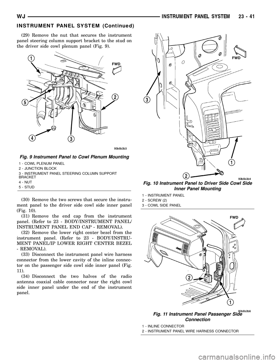
(29) Remove the nut that secures the instrument
panel steering column support bracket to the stud on
the driver side cowl plenum panel (Fig. 9).
(30) Remove the two screws that secure the instru-
ment panel to the driver side cowl side inner panel
(Fig. 10).
(31) Remove the end cap from the instrument
panel. (Refer to 23 - BODY/INSTRUMENT PANEL/
INSTRUMENT PANEL END CAP - REMOVAL).
(32) Remove the lower right center bezel from the
instrument panel. (Refer to 23 - BODY/INSTRU-
MENT PANEL/IP LOWER RIGHT CENTER BEZEL
- REMOVAL).
(33) Disconnect the instrument panel wire harness
connector from the lower cavity of the inline connec-
tor on the passenger side cowl side inner panel (Fig.
11).
(34) Disconnect the two halves of the radio
antenna coaxial cable connector near the right cowl
side inner panel under the end of the instrument
panel.
Fig. 9 Instrument Panel to Cowl Plenum Mounting
1 - COWL PLENUM PANEL
2 - JUNCTION BLOCK
3 - INSTRUMENT PANEL STEERING COLUMN SUPPORT
BRACKET
4 - NUT
5 - STUD
Fig. 10 Instrument Panel to Driver Side Cowl Side
Inner Panel Mounting
1 - INSTRUMENT PANEL
2 - SCREW (2)
3 - COWL SIDE PANEL
Fig. 11 Instrument Panel Passenger Side
Connection
1 - INLINE CONNECTOR
2 - INSTRUMENT PANEL WIRE HARNESS CONNECTOR
WJINSTRUMENT PANEL SYSTEM 23 - 41
INSTRUMENT PANEL SYSTEM (Continued)
Page 1916 of 2199

INSTALLATION
WARNING: ON VEHICLES EQUIPPED WITH AIR-
BAGS, DISABLE THE AIRBAG SYSTEM BEFORE
ATTEMPTING ANY STEERING WHEEL, STEERING
COLUMN, OR INSTRUMENT PANEL COMPONENT
DIAGNOSIS OR SERVICE. DISCONNECT AND ISO-
LATE THE BATTERY NEGATIVE (GROUND) CABLE,
THEN WAIT TWO MINUTES FOR THE AIRBAG SYS-
TEM CAPACITOR TO DISCHARGE BEFORE PER-
FORMING FURTHER DIAGNOSIS OR SERVICE. THIS
IS THE ONLY SURE WAY TO DISABLE THE AIRBAG
SYSTEM. FAILURE TO TAKE THE PROPER PRE-
CAUTIONS COULD RESULT IN ACCIDENTAL AIR-
BAG DEPLOYMENT AND POSSIBLE PERSONAL
INJURY.
(1) Prior to installing the instrument panel into
the vehicle, loosen the three nuts that secure the
instrument panel intermediate bracket and the accel-
erator pedal assembly to the studs on the dash panel
(Fig. 8).
(2) With the aid of an assistant, load the instru-
ment panel assembly through the driver side front
door of the vehicle and hang it on the studs on the
dash panel near the windshield fence line (Fig. 1).
(3) Be certain that the molded plastic hook forma-
tions on the instrument panel structural duct are
inserted into and seated in the guide holes at each
cowl side inner panel.
(4) Loosely install the two screws that secure each
end of the instrument panel to the cowl side inner
panels.
(5) Install and tighten the two screws that secure
the passenger side instrument panel structural duct
to the heater and air conditioner housing (Fig. 13).
Tighten the screws to 11.8 N´m (105 in. lbs.).
(6) Install and tighten the one screw that secures
the instrument panel steering column support
bracket to the driver side end of the heater and air
conditioner housing (Fig. 7). Tighten the screw to
11.8 N´m (105 in. lbs.).
(7) Tighten the two screws that secure each end of
the instrument panel to the cowl side inner panels
(Fig. 10) and (Fig. 14). Tighten the screws to 11.8
N´m (105 in. lbs.).
(8) Install and tighten the one screw that secures
the instrument panel steering column support
bracket to the intermediate bracket on the driver
side dash panel (Fig. 8). Tighten the screw to 11.3
N´m (100 in. lbs.).
(9) Tighten the three nuts that secure the instru-
ment panel intermediate bracket and the accelerator
pedal assembly to the studs on the dash panel.
Tighten the nuts to 11.3 N´m (100 in. lbs.).(10) Install and tighten the four nuts that secure
the instrument panel to the studs on the dash panel
near the windshield fence line. Tighten the nuts to
11.8 N´m (105 in. lbs.).
(11) Install and tighten the nut that secures the
instrument panel steering column support bracket to
the stud on the driver side cowl plenum panel (Fig.
9). Tighten the nut to 28.2 N´m (250 in. lbs.).
(12) Reinstall the instrument panel to center floor
tunnel bracket onto the instrument panel and the
floor panel transmission tunnel. (Refer to 23 - BODY/
INSTRUMENT PANEL/IP CENTER FLOOR TUN-
NEL BRACKET - INSTALLATION).
(13) Reconnect the two instrument panel wire har-
ness connectors to the two heater and air conditioner
housing connectors located near the blower motor on
the passenger side end of the housing (Fig. 12).
(14) Reconnect the two halves of the radio antenna
coaxial cable connector near the right cowl side inner
panel under the end of the instrument panel.
(15) Reconnect the instrument panel wire harness
connector to the lower cavity of the inline connector
on the passenger side cowl side inner panel and
tighten the connector screw (Fig. 11). Tighten the
screw to 4 N´m (36 in. lbs.).
(16) Reinstall the lower right center bezel onto the
instrument panel. (Refer to 23 - BODY/INSTRU-
MENT PANEL/IP LOWER RIGHT CENTER BEZEL
- INSTALLATION).
(17) Reinstall the end cap onto the instrument
panel. (Refer to 23 - BODY/INSTRUMENT PANEL/
INSTRUMENT PANEL END CAP - INSTALLA-
TION).
(18) If the vehicle is equipped with the manual
heating and air conditioning system, reconnect the
vacuum harness connector located near the driver
side of the floor panel transmission tunnel behind
the driver side floor duct.
(19) Position the driver side floor duct to the
heater and air conditioner housing near the driver
side of the floor panel transmission tunnel (Fig. 7).
(20) Install and tighten the one screw that secures
the driver side floor duct to the heater and air con-
ditioner housing near the driver side of the floor
panel transmission tunnel. Tighten the screw to 2.2
N´m (20 in. lbs.).
(21) Route the instrument panel wire harness to
the floor panel transmission tunnel and engage the
retainers that secure the harness to the mounting
brackets on the tunnel (Fig. 6).
(22) Install the instrument panel wire harness
ground eyelets to the studs on the floor panel trans-
mission tunnel in front of and behind the airbag con-
trol module and secure the eyelets with nuts. Tighten
the nuts to 7.3 N´m (65 in. lbs.).
WJINSTRUMENT PANEL SYSTEM 23 - 43
INSTRUMENT PANEL SYSTEM (Continued)
Page 1929 of 2199

INSTRUMENT PANEL C-
CHANNEL COVER BRACKET
REMOVAL
WARNING: ON VEHICLES EQUIPPED WITH AIRBAGS,
DISABLE THE AIRBAG SYSTEM BEFORE ATTEMPT-
ING ANY STEERING WHEEL, STEERING COLUMN, OR
INSTRUMENT PANEL COMPONENT DIAGNOSIS OR
SERVICE. DISCONNECT AND ISOLATE THE BATTERY
NEGATIVE (GROUND) CABLE, THEN WAIT TWO MIN-
UTES FOR THE AIRBAG SYSTEM CAPACITOR TO DIS-
CHARGE BEFORE PERFORMING FURTHER
DIAGNOSIS OR SERVICE. THIS IS THE ONLY SURE
WAY TO DISABLE THE AIRBAG SYSTEM. FAILURE TO
TAKE THE PROPER PRECAUTIONS COULD RESULT
IN ACCIDENTAL AIRBAG DEPLOYMENT AND POSSI-
BLE PERSONAL INJURY.
(1)Disconnect and isolate the battery negative cable.
(2) Remove the instrument panel from the vehicle.
(Refer to 23 - BODY/INSTRUMENT PANEL -
REMOVAL).
(3) Place the instrument panel top down on a suit-
able work surface. Be certain to take the proper pre-
cautions to protect the top of the instrument panel
from any possible cosmetic damage.
(4) Disengage the radio antenna coaxial cable
retainer from the mounting hole in the instrument
panel wire harness mounting tab on the passenger
side outboard end of the instrument panel C-channel
cover bracket.
(5) Remove the screw that secures the instrument
panel wire harness mounting tab on the passenger
side outboard end of the instrument panel C-channel
cover bracket (Fig. 26).
(6) Remove the screw that secures the passenger
side courtesy lamp to the lower tab of instrument
panel C-channel cover bracket.
(7) Remove the eight screws that secure the
C-channel cover bracket to the instrument panel
structural duct.
(8) Remove the C-channel cover bracket from the
instrument panel structural duct.
INSTALLATION
WARNING: ON VEHICLES EQUIPPED WITH AIRBAGS,
DISABLE THE AIRBAG SYSTEM BEFORE ATTEMPT-
ING ANY STEERING WHEEL, STEERING COLUMN, OR
INSTRUMENT PANEL COMPONENT DIAGNOSIS OR
SERVICE. DISCONNECT AND ISOLATE THE BATTERY
NEGATIVE (GROUND) CABLE, THEN WAIT TWO MIN-
UTES FOR THE AIRBAG SYSTEM CAPACITOR TO DIS-
CHARGE BEFORE PERFORMING FURTHER
DIAGNOSIS OR SERVICE. THIS IS THE ONLY SUREWAY TO DISABLE THE AIRBAG SYSTEM. FAILURE TO
TAKE THE PROPER PRECAUTIONS COULD RESULT
IN ACCIDENTAL AIRBAG DEPLOYMENT AND POSSI-
BLE PERSONAL INJURY.
(1) Position the C-channel cover bracket to the
instrument panel structural duct.
(2) Install and tighten the eight screws that secure
the C-channel cover bracket to the instrument panel
structural duct (Fig. 26). Tighten the screws to 2.2
N´m (20 in. lbs.).
(3) Position the passenger side courtesy lamp to
the lower tab of instrument panel C-channel cover
bracket.
(4) Install and tighten the screw that secures the
passenger side courtesy lamp to the lower tab of
instrument panel C-channel cover bracket. Tighten
the screw to 2.2 N´m (20 in. lbs.).
(5) Position the instrument panel wire harness
mounting tab to the passenger side outboard end of
the instrument panel C-channel cover bracket.
(6) Install and tighten the screw that secures the
instrument panel wire harness mounting tab to the
passenger side outboard end of the instrument panel
C-channel cover bracket. Tighten the screw to 2.2
N´m (20 in. lbs.).
(7) Engage the radio antenna coaxial cable
retainer in the mounting hole in the instrument
panel wire harness mounting tab on the passenger
side outboard end of the instrument panel C-channel
cover bracket.
(8) Reinstall the instrument panel into the vehicle.
(Refer to 23 - BODY/INSTRUMENT PANEL -
INSTALLATION).
(9) Reconnect the battery negative cable.
Fig. 26 Instrument Panel C-Channel Cover Bracket
Remove/Install
1 - C-CHANNEL COVER BRACKET
2 - SCREWS (8)
3 - PASSENGER SIDE COURTESY LAMP
4 - INSTRUMENT PANEL WIRE HARNESS
5 - STRUCTURAL DUCT
23 - 56 INSTRUMENT PANEL SYSTEMWJ