2003 JEEP GRAND CHEROKEE Panel
[x] Cancel search: PanelPage 1241 of 2199
FuseandBatteryin the index in this service man-
ual for the location of additional service information
covering the ignition-off draw fuse and the battery.
FUSE COVER
REMOVAL
(1) Disconnect and isolate the battery negative
cable.
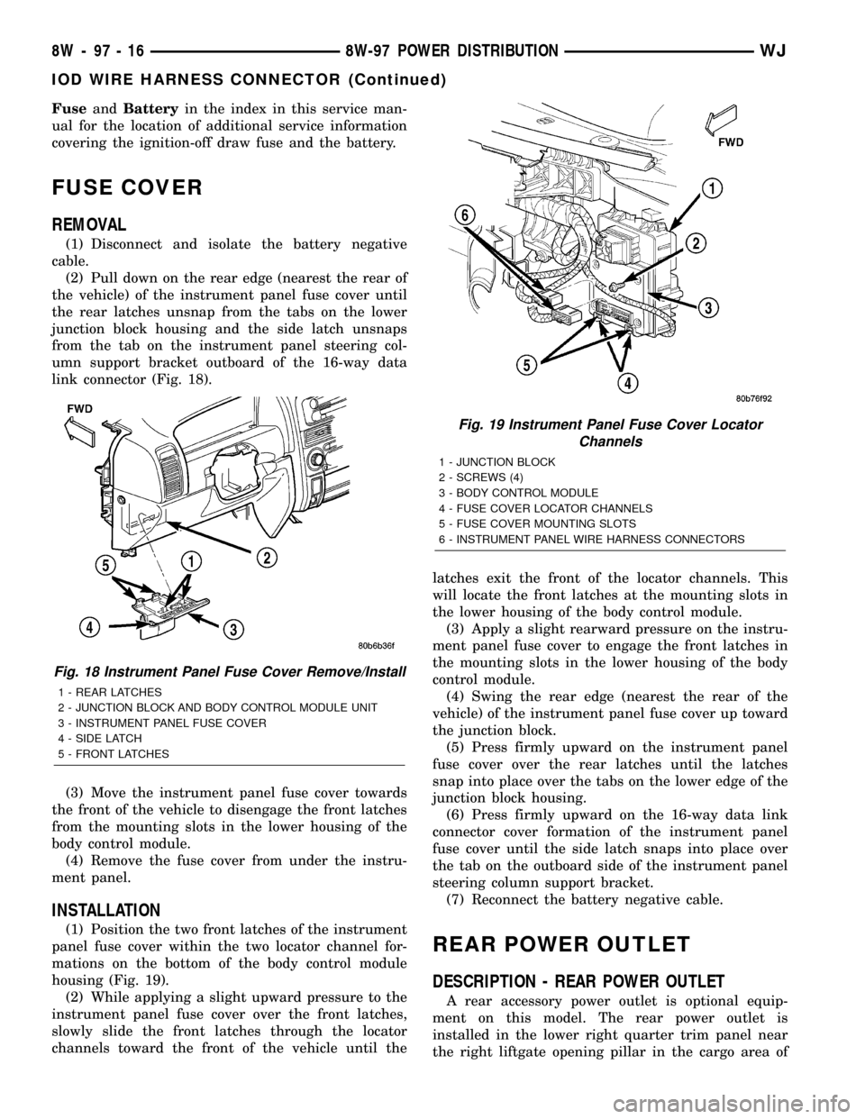
(2) Pull down on the rear edge (nearest the rear of
the vehicle) of the instrument panel fuse cover until
the rear latches unsnap from the tabs on the lower
junction block housing and the side latch unsnaps
from the tab on the instrument panel steering col-
umn support bracket outboard of the 16-way data
link connector (Fig. 18).
(3) Move the instrument panel fuse cover towards
the front of the vehicle to disengage the front latches
from the mounting slots in the lower housing of the
body control module.
(4) Remove the fuse cover from under the instru-
ment panel.
INSTALLATION
(1) Position the two front latches of the instrument
panel fuse cover within the two locator channel for-
mations on the bottom of the body control module
housing (Fig. 19).
(2) While applying a slight upward pressure to the
instrument panel fuse cover over the front latches,
slowly slide the front latches through the locator
channels toward the front of the vehicle until thelatches exit the front of the locator channels. This
will locate the front latches at the mounting slots in
the lower housing of the body control module.
(3) Apply a slight rearward pressure on the instru-
ment panel fuse cover to engage the front latches in
the mounting slots in the lower housing of the body
control module.
(4) Swing the rear edge (nearest the rear of the
vehicle) of the instrument panel fuse cover up toward
the junction block.
(5) Press firmly upward on the instrument panel
fuse cover over the rear latches until the latches
snap into place over the tabs on the lower edge of the
junction block housing.
(6) Press firmly upward on the 16-way data link
connector cover formation of the instrument panel
fuse cover until the side latch snaps into place over
the tab on the outboard side of the instrument panel
steering column support bracket.
(7) Reconnect the battery negative cable.
REAR POWER OUTLET
DESCRIPTION - REAR POWER OUTLET
A rear accessory power outlet is optional equip-
ment on this model. The rear power outlet is
installed in the lower right quarter trim panel near
the right liftgate opening pillar in the cargo area of
Fig. 18 Instrument Panel Fuse Cover Remove/Install
1 - REAR LATCHES
2 - JUNCTION BLOCK AND BODY CONTROL MODULE UNIT
3 - INSTRUMENT PANEL FUSE COVER
4 - SIDE LATCH
5 - FRONT LATCHES
Fig. 19 Instrument Panel Fuse Cover Locator
Channels
1 - JUNCTION BLOCK
2 - SCREWS (4)
3 - BODY CONTROL MODULE
4 - FUSE COVER LOCATOR CHANNELS
5 - FUSE COVER MOUNTING SLOTS
6 - INSTRUMENT PANEL WIRE HARNESS CONNECTORS
8W - 97 - 16 8W-97 POWER DISTRIBUTIONWJ
IOD WIRE HARNESS CONNECTOR (Continued)
Page 1242 of 2199
the vehicle. The power outlet base and mount are
secured by a snap fit within the quarter trim panel.
A plastic protective cap snaps into the power outlet
base when the power outlet is not being used, and
hangs from the power outlet base mount by an inte-
gral bail strap while the power outlet is in use. While
the power outlet is very similar to a cigar lighter
base unit, it does not include the two small spring-
clip retainers inside the bottom of the receptacle
shell that are used to secure the cigar lighter heating
element to the insulated contact.
The power outlet receptacle unit and the accessory
power outlet protective cap are available for service.
The power outlet receptacle cannot be repaired and,
if faulty or damaged, it must be replaced.
OPERATION - REAR POWER OUTLET
The power outlet base or receptacle shell is con-
nected to ground, and an insulated contact in the
bottom of the shell is connected to battery current.
The power outlet receives battery voltage from a fuse
in the Power Distribution Center (PDC) through a
fuse in the Junction Block (JB) at all times. Refer to
Horn/Cigar Lighter/Power Outletin Wiring Dia-
grams for the location of complete rear power outlet
circuit diagrams.
DIAGNOSIS AND TESTING - REAR POWER
OUTLET
Refer toHorn/Cigar Lighter/Power Outletin
Wiring Diagrams for the location of complete rear
power outlet circuit diagrams.
(1) Check the fused B(+) fuse in the Junction
Block (JB). If OK, go to Step 2. If not OK, repair the
shorted circuit or component as required and replace
the faulty fuse.
(2) Check for battery voltage at the fused B(+) fuse
in the JB. If OK, go to Step 3. If not OK, repair the
open fused B(+) circuit to the Power Distribution
Center (PDC) as required.
(3) Remove the plastic protective cap from the rear
power outlet receptacle. Check for continuity between
the inside circumference of the rear power outlet
receptacle and a good ground. There should be conti-
nuity. If OK, go to Step 4. If not OK, go to Step 5.
(4) Check for battery voltage at the insulated con-
tact located at the back of the rear power outlet
receptacle. If not OK, go to Step 5.(5) Disconnect and isolate the battery negative
cable. Remove the rear power outlet from the right
quarter trim panel. Check for continuity between the
ground circuit cavity of the rear power outlet wire
harness connector and a good ground. There should
be continuity. If OK, go to Step 6. If not OK, repair
the open ground circuit to ground as required.
(6) Connect the battery negative cable. Check for
battery voltage at the fused B(+) circuit cavity of the
rear power outlet wire harness connector. If OK,
replace the faulty rear power outlet receptacle base.
If not OK, repair the open fused B(+) circuit to the
JB fuse as required.
REMOVAL
(1) Disconnect and isolate the battery negative
cable.
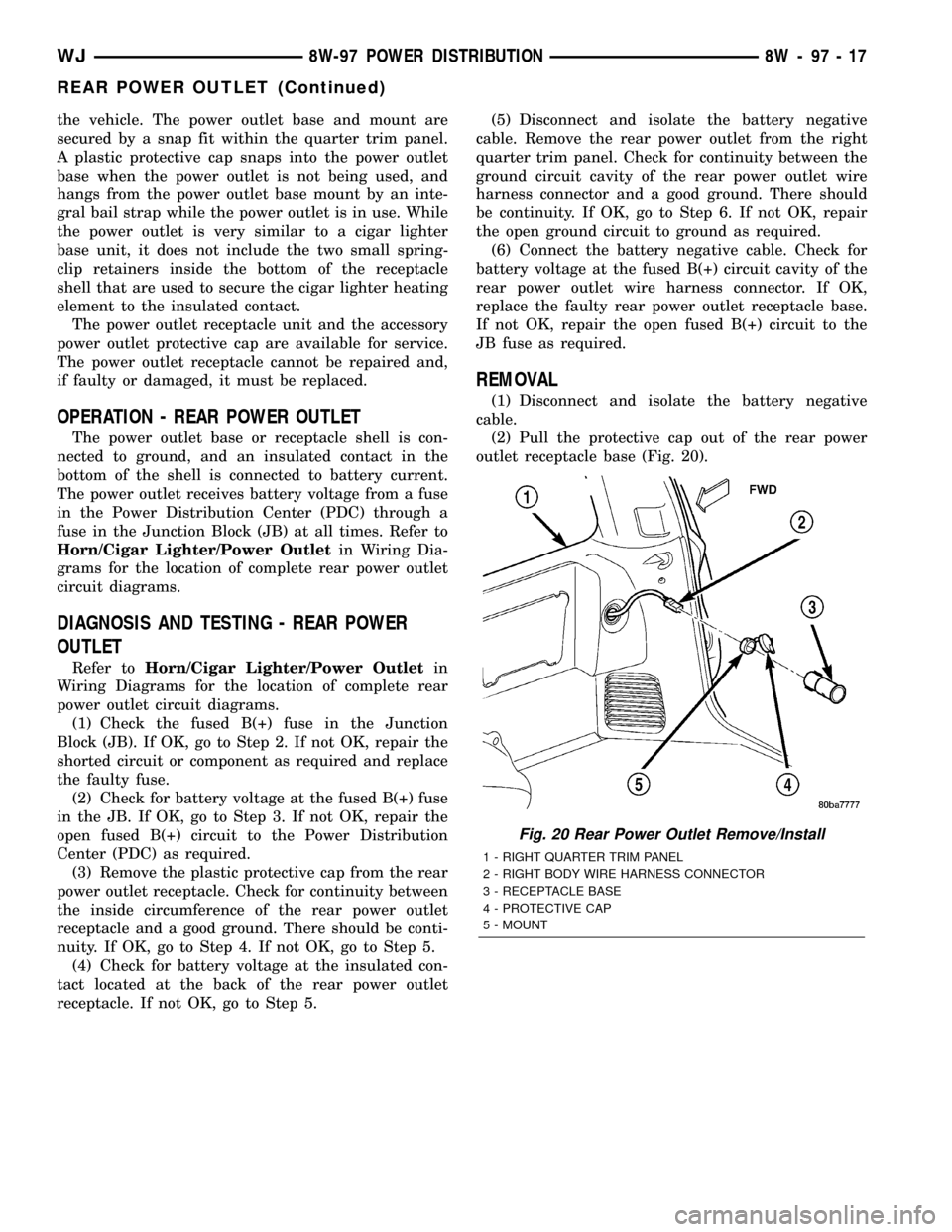
(2) Pull the protective cap out of the rear power
outlet receptacle base (Fig. 20).
Fig. 20 Rear Power Outlet Remove/Install
1 - RIGHT QUARTER TRIM PANEL
2 - RIGHT BODY WIRE HARNESS CONNECTOR
3 - RECEPTACLE BASE
4 - PROTECTIVE CAP
5 - MOUNT
WJ8W-97 POWER DISTRIBUTION 8W - 97 - 17
REAR POWER OUTLET (Continued)
Page 1243 of 2199
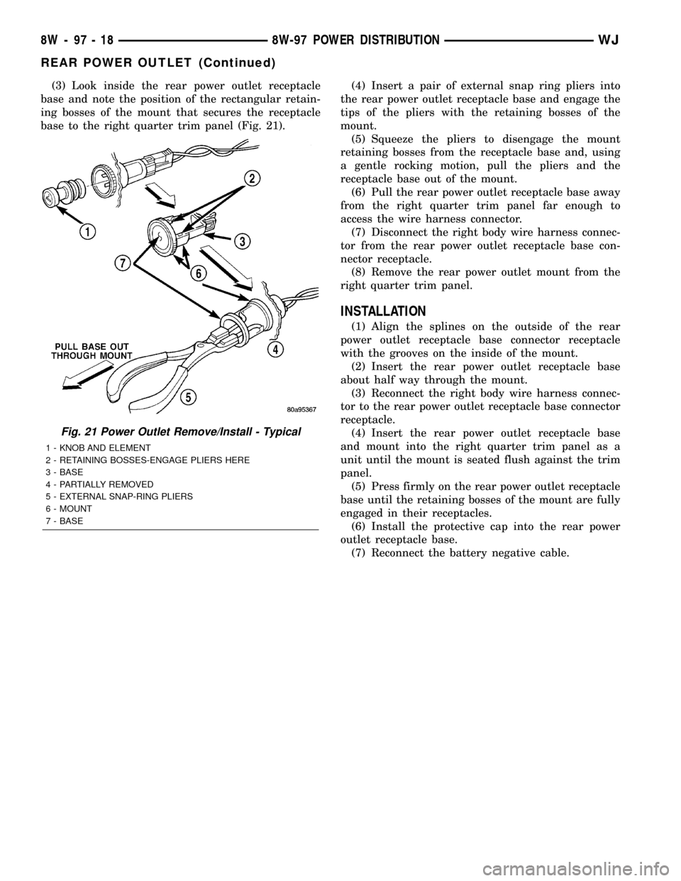
(3) Look inside the rear power outlet receptacle
base and note the position of the rectangular retain-
ing bosses of the mount that secures the receptacle
base to the right quarter trim panel (Fig. 21).(4) Insert a pair of external snap ring pliers into
the rear power outlet receptacle base and engage the
tips of the pliers with the retaining bosses of the
mount.
(5) Squeeze the pliers to disengage the mount
retaining bosses from the receptacle base and, using
a gentle rocking motion, pull the pliers and the
receptacle base out of the mount.
(6) Pull the rear power outlet receptacle base away
from the right quarter trim panel far enough to
access the wire harness connector.
(7) Disconnect the right body wire harness connec-
tor from the rear power outlet receptacle base con-
nector receptacle.
(8) Remove the rear power outlet mount from the
right quarter trim panel.
INSTALLATION
(1) Align the splines on the outside of the rear
power outlet receptacle base connector receptacle
with the grooves on the inside of the mount.
(2) Insert the rear power outlet receptacle base
about half way through the mount.
(3) Reconnect the right body wire harness connec-
tor to the rear power outlet receptacle base connector
receptacle.
(4) Insert the rear power outlet receptacle base
and mount into the right quarter trim panel as a
unit until the mount is seated flush against the trim
panel.
(5) Press firmly on the rear power outlet receptacle
base until the retaining bosses of the mount are fully
engaged in their receptacles.
(6) Install the protective cap into the rear power
outlet receptacle base.
(7) Reconnect the battery negative cable.
Fig. 21 Power Outlet Remove/Install - Typical
1 - KNOB AND ELEMENT
2 - RETAINING BOSSES-ENGAGE PLIERS HERE
3 - BASE
4 - PARTIALLY REMOVED
5 - EXTERNAL SNAP-RING PLIERS
6 - MOUNT
7 - BASE
8W - 97 - 18 8W-97 POWER DISTRIBUTIONWJ
REAR POWER OUTLET (Continued)
Page 1254 of 2199
CAUTION: DO NOT use engine or transmission oil,
mineral spirits, or kerosene.
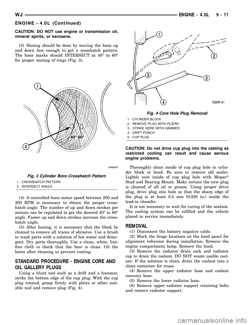
(3) Honing should be done by moving the hone up
and down fast enough to get a crosshatch pattern.
The hone marks should INTERSECT at 40É to 60É
for proper seating of rings (Fig. 3).
(4) A controlled hone motor speed between 200 and
300 RPM is necessary to obtain the proper cross-
hatch angle. The number of up and down strokes per
minute can be regulated to get the desired 40É to 60É
angle. Faster up and down strokes increase the cross-
hatch angle.
(5) After honing, it is necessary that the block be
cleaned to remove all traces of abrasive. Use a brush
to wash parts with a solution of hot water and deter-
gent. Dry parts thoroughly. Use a clean, white, lint-
free cloth to check that the bore is clean. Oil the
bores after cleaning to prevent rusting.
STANDARD PROCEDURE - ENGINE CORE AND
OIL GALLERY PLUGS
Using a blunt tool such as a drift and a hammer,
strike the bottom edge of the cup plug. With the cup
plug rotated, grasp firmly with pliers or other suit-
able tool and remove plug (Fig. 4).CAUTION: Do not drive cup plug into the casting as
restricted cooling can result and cause serious
engine problems.
Thoroughly clean inside of cup plug hole in cylin-
der block or head. Be sure to remove old sealer.
Lightly coat inside of cup plug hole with Mopart
Stud and Bearing Mount. Make certain the new plug
is cleaned of all oil or grease. Using proper drive
plug, drive plug into hole so that the sharp edge of
the plug is at least 0.5 mm (0.020 in.) inside the
lead-in chamfer.
It is not necessary to wait for curing of the sealant.
The cooling system can be refilled and the vehicle
placed in service immediately.
REMOVAL
(1) Disconnect the battery negative cable.
(2) Mark the hinge locations on the hood panel for
alignment reference during installation. Remove the
engine compartment lamp. Remove the hood.
(3) Remove the radiator drain cock and radiator
cap to drain the coolant. DO NOT waste usable cool-
ant. If the solution is clean, drain the coolant into a
clean container for reuse.
(4) Remove the upper radiator hose and coolant
recovery hose.
(5) Remove the lower radiator hose.
(6) Remove upper radiator support retaining bolts
and remove radiator support.
Fig. 3 Cylinder Bore Crosshatch Pattern
1 - CROSSHATCH PATTERN
2 - INTERSECT ANGLE
Fig. 4 Core Hole Plug Removal
1 - CYLINDER BLOCK
2 - REMOVE PLUG WITH PLIERS
3 - STRIKE HERE WITH HAMMER
4 - DRIFT PUNCH
5 - CUP PLUG
WJENGINE - 4.0L 9 - 11
ENGINE - 4.0L (Continued)
Page 1299 of 2199

(9) Lower the engine until it is properly located on
the engine mounts.
(10) Install the through bolts and tighten the nuts.
(11) Lower the jack stand and remove the piece of
wood.
(12) Install the engine flywheel and transmission
torque converter housing access cover.
(13) Install the engine starter motor. (Refer to 8 -
ELECTRICAL/STARTING/STARTER MOTOR -
INSTALLATION).
(14) Connect the exhaust pipe to the hanger and to
the engine exhaust manifold.
(15) Install transmission oil cooling lines (if
equipped) and oxygen sensor wiring supports that
attach to the oil pan studs.
(16) Install the oil pan drain plug (Fig. 81).
Tighten the plug to 34 N´m (25 ft. lbs.) torque.
(17) Lower the vehicle.
(18) Connect negative cable to battery.
(19) Fill the oil pan with engine oil to the specified
level.
WARNING: USE EXTREME CAUTION WHEN THE
ENGINE IS OPERATING. DO NOT STAND IN A
DIRECT LINE WITH THE FAN. DO NOT PUT YOUR
HANDS NEAR THE PULLEYS, BELTS OR FAN. DO
NOT WEAR LOOSE CLOTHING.
(20) Start the engine and inspect for leaks.
ENGINE OIL PRESSURE
SENSOR
DESCRIPTION
The 3±wire, solid-state engine oil pressure sensor
(sending unit) is located in an engine oil pressure
gallery.
OPERATION
The oil pressure sensor uses three circuits. They
are:
²A 5±volt power supply from the Powertrain Con-
trol Module (PCM)
²A sensor ground through the PCM's sensor
return
²A signal to the PCM relating to engine oil pres-
sure
The oil pressure sensor has a 3±wire electrical
function very much like the Manifold Absolute Pres-
sure (MAP) sensor. Meaning different pressures
relate to different output voltages.
A 5±volt supply is sent to the sensor from the PCM
to power up the sensor. The sensor returns a voltage
signal back to the PCM relating to engine oil pres-
sure. This signal is then transferred (bussed) to theinstrument panel on either a CCD or PCI bus circuit
(depending on vehicle line) to operate the oil pressure
gauge and the check gauges lamp. Ground for the
sensor is provided by the PCM through a low-noise
sensor return.
OIL PUMP
REMOVAL
A gear-type oil pump is mounted at the underside
of the cylinder block opposite the No.4 main bearing.
(1) Drain the engine oil.
(2) Remove the oil pan (Refer to 9 - ENGINE/LU-
BRICATION/OIL PAN - REMOVAL).
(3) Remove the pump-to-cylinder block attaching
bolts. Remove the pump assembly with gasket (Fig.
82).
CAUTION: If the oil pump is not to be serviced, DO
NOT disturb position of oil inlet tube and strainer
assembly in pump body. If the tube is moved within
the pump body, a replacement tube and strainer
assembly must be installed to assure an airtight
seal.
Fig. 82 Oil Pump Assembly
1 - OIL FILTER ADAPTOR
2 - BLOCK
3 - GASKET
4 - OIL INLET TUBE
5 - OIL PUMP
6 - STRAINER ASSEMBLY
7 - ATTACHING BOLTS
9 - 56 ENGINE - 4.0LWJ
OIL PAN (Continued)
Page 1376 of 2199

NOTE: When installing oil pan gasket/windage tray,
start four pan bolts at each corner before tightening
oil pickup tube. This will keep pan gasket in align-
ment.
(3) Install oil pump pick-up tube using a new
O-ring. First tighten bolt at O-ring end of tube to 28
N´m (20 ft. lbs.). Tighten remain tube support fasten-
ers to 28 N´m (20 ft. lbs.).
(4) Install oil pan and tighten fasteners to 15 N´m
(11 ft. lbs.) (Fig. 95).
(5) Reconnect transmission oil cooler lines to oil
pan stud bolt.
(6) Install starter (Refer to 8 - ELECTRICAL/
STARTING/STARTER MOTOR - INSTALLATION).
(7) Install exhaust system Y-pipe.
(8) Install structural cover (Refer to 9 - ENGINE/
ENGINE BLOCK/STRUCTURAL COVER - INSTAL-
LATION).
(9) Lower vehicle.
(10) Fill engine with proper amount of oil (Refer to
LUBRICATION & MAINTENANCE/FLUID TYPES -
SPECIFICATIONS).
(11) Connect negative cable to battery.
OIL PRESSURE SENSOR/
SWITCH
DESCRIPTION
The 3±wire, solid-state engine oil pressure sensor
(sending unit) is located in an engine oil pressure
gallery.
OPERATION
The oil pressure sensor uses three circuits. They are:
²A 5±volt power supply from the Powertrain Con-
trol Module (PCM)
²A sensor ground through the PCM's sensor
return
²
A signal to the PCM relating to engine oil pressure
The oil pressure sensor has a 3±wire electrical
function very much like the Manifold Absolute Pres-
sure (MAP) sensor. Meaning different pressures
relate to different output voltages.
A 5±volt supply is sent to the sensor from the PCM
to power up the sensor. The sensor returns a voltage
signal back to the PCM relating to engine oil pres-
sure. This signal is then transferred (bussed) to the
instrument panel on either a CCD or PCI bus circuit
(depending on vehicle line) to operate the oil pressure
gauge and the check gauges lamp. Ground for the
sensor is provided by the PCM through a low-noise
sensor return.
REMOVAL
(1) Disconnect the negative cable from the battery.
(2) Raise vehicle on hoist.
(3) Remove front splash shield.
(4) Disconnect oil pressure sender wire (Fig. 96).
(5) Remove the pressure sender (Fig. 96).
INSTALLATION
(1) Install oil pressure sender.
(2) Connect oil pressure sender wire.
(3) Install front splash shield.
(4) Lower vehicle.
(5) Connect the negative battery cable.
Fig. 95 Oil Pan Tightening Sequence
Fig. 96 Oil Pressure Sending Unit
1 - BELT
2 - OIL PRESSURE SENSOR
3 - OIL FILTER
4 - ELEC. CONNECTOR
WJENGINE - 4.7L 9 - 133
OIL PAN (Continued)
Page 1398 of 2199
EXHAUST SYSTEM
TABLE OF CONTENTS
page page
EXHAUST SYSTEM
DESCRIPTION - EXHAUST SYSTEM.........1
DIAGNOSIS AND TESTING - EXHAUST
SYSTEM.............................3
SPECIFICATIONS
TORQUE.............................3
CATALYTIC CONVERTER - 4.0L
DESCRIPTION - CATALYTIC CONVERTER
4.0L ENGINE..........................4
REMOVAL.............................4
INSPECTION...........................5
INSTALLATION..........................5
CATALYTIC CONVERTER - 4.7L
DESCRIPTION - CATALYTIC CONVERTER.....6
REMOVAL.............................6
INSPECTION...........................7
INSTALLATION..........................7EXHAUST PIPE - 4.0L
REMOVAL.............................8
INSPECTION...........................8
INSTALLATION..........................8
EXHAUST PIPE - 4.7L
REMOVAL.............................10
INSPECTION..........................10
INSTALLATION.........................10
HEAT SHIELDS
DESCRIPTION.........................12
MUFFLER
DESCRIPTION.........................12
REMOVAL.............................12
INSTALLATION.........................12
TAILPIPE
DESCRIPTION.........................13
OPERATION...........................13
EXHAUST SYSTEM
DESCRIPTION - EXHAUST SYSTEM
WARNING: THE NORMAL OPERATING TEMPERA-
TURE OF THE EXHAUST SYSTEM IS VERY HIGH.
THEREFORE, NEVER WORK AROUND OR ATTEMPT
TO SERVICE ANY PART OF THE EXHAUST SYSTEM
UNTIL IT IS COOLED. SPECIAL CARE SHOULD BE
TAKEN WHEN WORKING NEAR THE CATALYTIC
CONVERTER. THE TEMPERATURE OF THE CON-
VERTER RISES TO A HIGH LEVEL AFTER A SHORT
PERIOD OF ENGINE OPERATION TIME.
CAUTION: Avoid application of rust prevention com-
pounds or undercoating materials to exhaust sys-
tem floor pan heat shields. Light overspray near the
edges is permitted. Application of coating will result
in excessive floor pan temperatures and objection-
able fumes.
The exhaust system uses a single muffler with a
welded tailpipe.The 50 State Emissions vehicles use two mini cat-
alytic converters inline with the exhaust pipe below
the exhaust manifolds.
The exhaust manifolds are equipped with ball
flange outlets to assure a tight seal and strain free
connections.
The exhaust system must be properly aligned to
prevent stress, leakage and body contact. If the sys-
tem contacts any body panel, it may amplify objec-
tionable noises originating from the engine or body.
When inspecting an exhaust system, critically
inspect for cracked or loose joints, stripped screw or
bolt threads, corrosion damage and worn, cracked or
broken hangers. Replace all components that are
badly corroded or damaged. DO NOT attempt to
repair.
When replacement is required, use original equip-
ment parts (or their equivalent). This will assure
proper alignment and provide acceptable exhaust
noise levels.
The basic exhaust system consists of exhaust man-
ifold(s), exhaust pipe with oxygen sensors, catalytic
converter(s), heat shield(s), muffler and tailpipe (Fig.
1) and (Fig. 2).
WJEXHAUST SYSTEM 11 - 1
Page 1402 of 2199
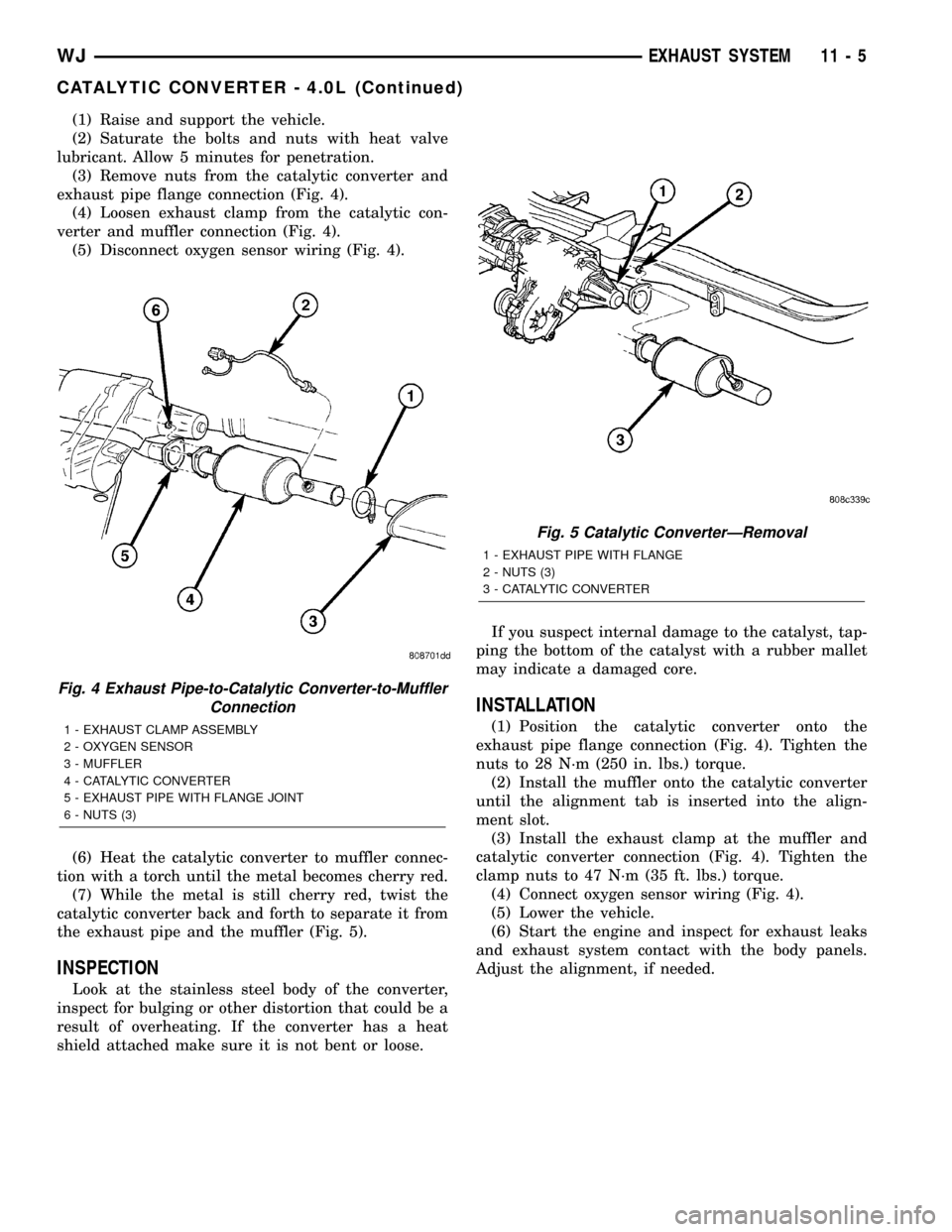
(1) Raise and support the vehicle.
(2) Saturate the bolts and nuts with heat valve
lubricant. Allow 5 minutes for penetration.
(3) Remove nuts from the catalytic converter and
exhaust pipe flange connection (Fig. 4).
(4) Loosen exhaust clamp from the catalytic con-
verter and muffler connection (Fig. 4).
(5) Disconnect oxygen sensor wiring (Fig. 4).
(6) Heat the catalytic converter to muffler connec-
tion with a torch until the metal becomes cherry red.
(7) While the metal is still cherry red, twist the
catalytic converter back and forth to separate it from
the exhaust pipe and the muffler (Fig. 5).
INSPECTION
Look at the stainless steel body of the converter,
inspect for bulging or other distortion that could be a
result of overheating. If the converter has a heat
shield attached make sure it is not bent or loose.If you suspect internal damage to the catalyst, tap-
ping the bottom of the catalyst with a rubber mallet
may indicate a damaged core.
INSTALLATION
(1) Position the catalytic converter onto the
exhaust pipe flange connection (Fig. 4). Tighten the
nuts to 28 N´m (250 in. lbs.) torque.
(2) Install the muffler onto the catalytic converter
until the alignment tab is inserted into the align-
ment slot.
(3) Install the exhaust clamp at the muffler and
catalytic converter connection (Fig. 4). Tighten the
clamp nuts to 47 N´m (35 ft. lbs.) torque.
(4) Connect oxygen sensor wiring (Fig. 4).
(5) Lower the vehicle.
(6) Start the engine and inspect for exhaust leaks
and exhaust system contact with the body panels.
Adjust the alignment, if needed.
Fig. 4 Exhaust Pipe-to-Catalytic Converter-to-Muffler
Connection
1 - EXHAUST CLAMP ASSEMBLY
2 - OXYGEN SENSOR
3 - MUFFLER
4 - CATALYTIC CONVERTER
5 - EXHAUST PIPE WITH FLANGE JOINT
6 - NUTS (3)
Fig. 5 Catalytic ConverterÐRemoval
1 - EXHAUST PIPE WITH FLANGE
2 - NUTS (3)
3 - CATALYTIC CONVERTER
WJEXHAUST SYSTEM 11 - 5
CATALYTIC CONVERTER - 4.0L (Continued)