2003 JEEP GRAND CHEROKEE position sensor
[x] Cancel search: position sensorPage 2099 of 2199
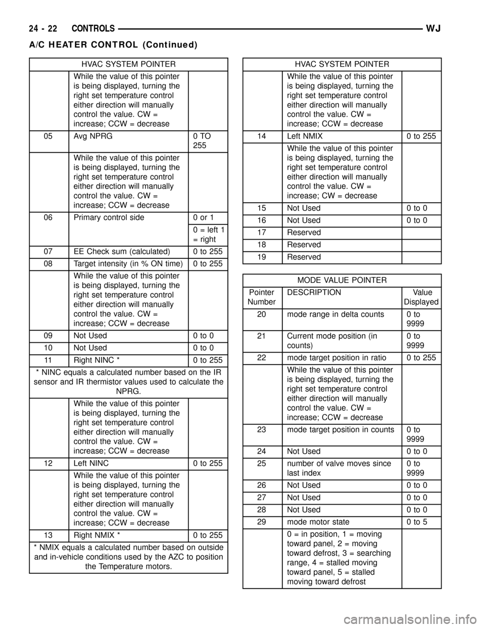
HVAC SYSTEM POINTER
While the value of this pointer
is being displayed, turning the
right set temperature control
either direction will manually
control the value. CW =
increase; CCW = decrease
05 Avg NPRG 0 TO
255
While the value of this pointer
is being displayed, turning the
right set temperature control
either direction will manually
control the value. CW =
increase; CCW = decrease
06 Primary control side 0 or 1
0 = left 1
= right
07 EE Check sum (calculated) 0 to 255
08 Target intensity (in % ON time) 0 to 255
While the value of this pointer
is being displayed, turning the
right set temperature control
either direction will manually
control the value. CW =
increase; CCW = decrease
09 Not Used 0 to 0
10 Not Used 0 to 0
11 Right NINC * 0 to 255
* NINC equals a calculated number based on the IR
sensor and IR thermistor values used to calculate the
NPRG.
While the value of this pointer
is being displayed, turning the
right set temperature control
either direction will manually
control the value. CW =
increase; CCW = decrease
12 Left NINC 0 to 255
While the value of this pointer
is being displayed, turning the
right set temperature control
either direction will manually
control the value. CW =
increase; CCW = decrease
13 Right NMIX * 0 to 255
* NMIX equals a calculated number based on outside
and in-vehicle conditions used by the AZC to position
the Temperature motors.HVAC SYSTEM POINTER
While the value of this pointer
is being displayed, turning the
right set temperature control
either direction will manually
control the value. CW =
increase; CCW = decrease
14 Left NMIX 0 to 255
While the value of this pointer
is being displayed, turning the
right set temperature control
either direction will manually
control the value. CW =
increase; CW = decrease
15 Not Used 0 to 0
16 Not Used 0 to 0
17 Reserved
18 Reserved
19 Reserved
MODE VALUE POINTER
Pointer
NumberDESCRIPTION Value
Displayed
20 mode range in delta counts 0 to
9999
21 Current mode position (in
counts)0to
9999
22 mode target position in ratio 0 to 255
While the value of this pointer
is being displayed, turning the
right set temperature control
either direction will manually
control the value. CW =
increase; CCW = decrease
23 mode target position in counts 0 to
9999
24 Not Used 0 to 0
25 number of valve moves since
last index0to
9999
26 Not Used 0 to 0
27 Not Used 0 to 0
28 Not Used 0 to 0
29 mode motor state 0 to 5
0 = in position, 1 = moving
toward panel, 2 = moving
toward defrost, 3 = searching
range, 4 = stalled moving
toward panel, 5 = stalled
moving toward defrost
24 - 22 CONTROLSWJ
A/C HEATER CONTROL (Continued)
Page 2101 of 2199
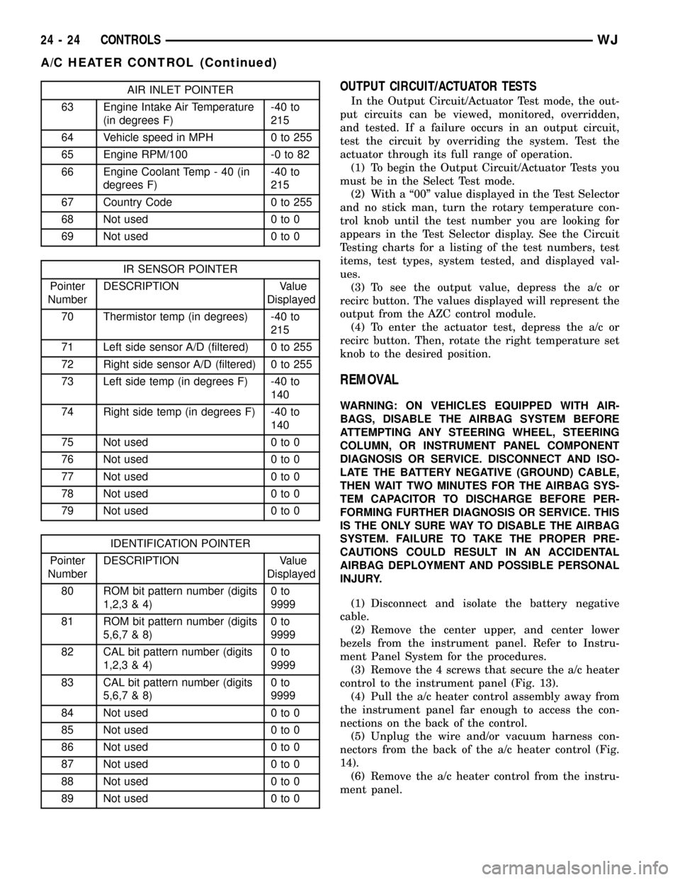
AIR INLET POINTER
63 Engine Intake Air Temperature
(in degrees F)-40 to
215
64 Vehicle speed in MPH 0 to 255
65 Engine RPM/100 -0 to 82
66 Engine Coolant Temp - 40 (in
degrees F)-40 to
215
67 Country Code 0 to 255
68 Not used 0 to 0
69 Not used 0 to 0
IR SENSOR POINTER
Pointer
NumberDESCRIPTION Value
Displayed
70 Thermistor temp (in degrees) -40 to
215
71 Left side sensor A/D (filtered) 0 to 255
72 Right side sensor A/D (filtered) 0 to 255
73 Left side temp (in degrees F) -40 to
140
74 Right side temp (in degrees F) -40 to
140
75 Not used 0 to 0
76 Not used 0 to 0
77 Not used 0 to 0
78 Not used 0 to 0
79 Not used 0 to 0
IDENTIFICATION POINTER
Pointer
NumberDESCRIPTION Value
Displayed
80 ROM bit pattern number (digits
1,2,3 & 4)0to
9999
81 ROM bit pattern number (digits
5,6,7 & 8)0to
9999
82 CAL bit pattern number (digits
1,2,3 & 4)0to
9999
83 CAL bit pattern number (digits
5,6,7 & 8)0to
9999
84 Not used 0 to 0
85 Not used 0 to 0
86 Not used 0 to 0
87 Not used 0 to 0
88 Not used 0 to 0
89 Not used 0 to 0
OUTPUT CIRCUIT/ACTUATOR TESTS
In the Output Circuit/Actuator Test mode, the out-
put circuits can be viewed, monitored, overridden,
and tested. If a failure occurs in an output circuit,
test the circuit by overriding the system. Test the
actuator through its full range of operation.
(1) To begin the Output Circuit/Actuator Tests you
must be in the Select Test mode.
(2) With a ª00º value displayed in the Test Selector
and no stick man, turn the rotary temperature con-
trol knob until the test number you are looking for
appears in the Test Selector display. See the Circuit
Testing charts for a listing of the test numbers, test
items, test types, system tested, and displayed val-
ues.
(3) To see the output value, depress the a/c or
recirc button. The values displayed will represent the
output from the AZC control module.
(4) To enter the actuator test, depress the a/c or
recirc button. Then, rotate the right temperature set
knob to the desired position.
REMOVAL
WARNING: ON VEHICLES EQUIPPED WITH AIR-
BAGS, DISABLE THE AIRBAG SYSTEM BEFORE
ATTEMPTING ANY STEERING WHEEL, STEERING
COLUMN, OR INSTRUMENT PANEL COMPONENT
DIAGNOSIS OR SERVICE. DISCONNECT AND ISO-
LATE THE BATTERY NEGATIVE (GROUND) CABLE,
THEN WAIT TWO MINUTES FOR THE AIRBAG SYS-
TEM CAPACITOR TO DISCHARGE BEFORE PER-
FORMING FURTHER DIAGNOSIS OR SERVICE. THIS
IS THE ONLY SURE WAY TO DISABLE THE AIRBAG
SYSTEM. FAILURE TO TAKE THE PROPER PRE-
CAUTIONS COULD RESULT IN AN ACCIDENTAL
AIRBAG DEPLOYMENT AND POSSIBLE PERSONAL
INJURY.
(1) Disconnect and isolate the battery negative
cable.
(2) Remove the center upper, and center lower
bezels from the instrument panel. Refer to Instru-
ment Panel System for the procedures.
(3) Remove the 4 screws that secure the a/c heater
control to the instrument panel (Fig. 13).
(4) Pull the a/c heater control assembly away from
the instrument panel far enough to access the con-
nections on the back of the control.
(5) Unplug the wire and/or vacuum harness con-
nectors from the back of the a/c heater control (Fig.
14).
(6) Remove the a/c heater control from the instru-
ment panel.
24 - 24 CONTROLSWJ
A/C HEATER CONTROL (Continued)
Page 2102 of 2199

INSTALLATION
(1) Plug the wire harness and/or vacuum harness
connectors into the back of the a/c heater control.
(2) Position the a/c heater control in the instru-
ment panel and secure it with 4 screws. Tighten the
screws to 2.2 N´m (20 in. lbs.).
(3) Reinstall the center upper, and center lower
bezels onto the instrument panel. Refer to Instru-
ment Panel System for the procedures.
(4) Connect the battery negative cable.
A/C PRESSURE TRANSDUCER
DESCRIPTION
The A/C pressure transducer is installed on a fit-
ting located on the refrigerant discharge line near
the condenser. An internally threaded hex fitting on
the transducer connects it to the externally threaded
Schrader-type fitting on the discharge line. A rubber
O-ring seals the connection between the transducer
and the discharge line fitting. Three terminals within
a molded plastic connector receptacle on the top of
the transducer connect it to the vehicle electrical sys-
tem through a take out and connector of the head-
lamp and dash wire harness.
The A/C pressure transducer cannot be adjusted or
repaired and if faulty or damaged, it must be
replaced.
OPERATION
The A/C pressure transducer monitors the pres-
sures in the high side of the refrigerant system
through its connection to a fitting on the discharge
line. The transducer will change its internal resis-
tance in response to the pressures it monitors. The
Powertrain Control Module (PCM) provides a five
volt reference signal and a sensor ground to the
transducer, then monitors the output voltage of the
transducer on a sensor return circuit to determine
refrigerant pressure. The PCM is preporgrammed to
respond to this and other sensor inputs by controlling
the operation of the air conditioning compressor
clutch and the radiator cooling fan to help optimize
air conditioning system performance and to protect
the system components from damage. The A/C pres-
sure transducer input to the PCM will also prevent
the air conditioning compressor clutch from engaging
when the ambient temperatures are below about
0.556É C (33É F) due to the pressure/temperature
relationship of the refrigerant. The Schrader-type
valve in the liquid line fitting permits the A/C pres-
sure transducer to be removed or installed without
distrubing the refrigerant in the system. The A/C
pressure transducer is diagnosed using the DRBIIIt
scan tool. Refer to the appropriate diagnostic infor-
mation.
Fig. 13 A/C HEATER CONTROL REMOVE/INSTALL
1 - MOUNTING SCREW TABS
Fig. 14 A/C HEATER CONTROL CONNECTIONS
1 - MODE SWITCH
2 - ELECTRICAL CONNECTIONS
3 - VACUUM HARNESS
WJCONTROLS 24 - 25
A/C HEATER CONTROL (Continued)
Page 2106 of 2199

WARNING: ON VEHICLES EQUIPPED WITH AIR-
BAGS, DISABLE THE AIRBAG SYSTEM BEFORE
ATTEMPTING ANY STEERING WHEEL, STEERING
COLUMN, OR INSTRUMENT PANEL COMPONENT
DIAGNOSIS OR SERVICE. DISCONNECT AND ISO-
LATE THE BATTERY NEGATIVE (GROUND) CABLE,
THEN WAIT TWO MINUTES FOR THE AIRBAG SYS-
TEM CAPACITOR TO DISCHARGE BEFORE PER-
FORMING FURTHER DIAGNOSIS OR SERVICE. THIS
IS THE ONLY SURE WAY TO DISABLE THE AIRBAG
SYSTEM. FAILURE TO TAKE THE PROPER PRE-
CAUTIONS COULD RESULT IN AN ACCIDENTAL
AIRBAG DEPLOYMENT AND POSSIBLE PERSONAL
INJURY.
(1) Check for battery voltage at the fuse in the
Power Distribution Center (PDC). If OK, go to Step
2. If not OK, repair the shorted circuit or component
as required and replace the faulty fuse.
(2) Turn the ignition switch to the Off position.
Disconnect and isolate the battery negative cable.
Remove the a/c heater control from the instrument
panel. (Refer to 24 - HEATING & AIR CONDITION-
ING/CONTROLS/A/C HEATER CONTROL -
REMOVAL) Check for continuity between the ground
circuit cavity of the a/c heater control wire harness
connector and a good ground. There should be conti-
nuity. If OK, go to Step 3. If not OK, repair the open
circuit to ground as required.
(3) With the a/c heater control wire harness con-
nector unplugged, place the a/c heater mode control
switch knob in any position except the Off position.
Check for continuity between the ground circuit ter-
minal and each of the blower motor driver circuit ter-
minals of the a/c heater control as you move the
blower motor switch knob to each of the four speed
positions. There should be continuity at each driver
circuit terminal in only one blower motor switch
speed position. If OK, test and repair the blower
driver circuits between the a/c heater control connec-
tor and the blower motor resistor as required. If not
OK, replace the faulty a/c heater control unit.
REMOVAL
WARNING: ON VEHICLES EQUIPPED WITH AIR-
BAGS, DISABLE THE AIRBAG SYSTEM BEFORE
ATTEMPTING ANY STEERING WHEEL, STEERING
COLUMN, OR INSTRUMENT PANEL COMPONENT
DIAGNOSIS OR SERVICE. DISCONNECT AND ISO-
LATE THE BATTERY NEGATIVE (GROUND) CABLE,
THEN WAIT TWO MINUTES FOR THE AIRBAG SYS-
TEM CAPACITOR TO DISCHARGE BEFORE PER-
FORMING FURTHER DIAGNOSIS OR SERVICE. THIS
IS THE ONLY SURE WAY TO DISABLE THE AIRBAG
SYSTEM. FAILURE TO TAKE THE PROPER PRE-
CAUTIONS COULD RESULT IN AN ACCIDENTALAIRBAG DEPLOYMENT AND POSSIBLE PERSONAL
INJURY.
The blower motor switch cannot be adjusted or
repaired, and if faulty or damaged, the a/c heater
control must be replaced. (Refer to 24 - HEATING &
AIR CONDITIONING/CONTROLS/A/C HEATER
CONTROL - REMOVAL)
IN-CAR TEMPERATURE
SENSOR
DESCRIPTION
Models equipped with the optional Automatic Zone
Control (AZC) system use automatic dual zone tem-
perature control with infrared sensing technology.
The temperature sensor is located in the center
instrument panel, between the dual temperature
knobs of the AZC.
OPERATION
The Automatic Zone Control uses infrared sensing
technology to control occupant comfort levels, not the
actual passenger compartment air temperature. Dual
infrared sensors mounted in the face of the control
unit independently measure the surface temperature
to maintain customer-perceived comfort temperature
under changing conditions. Dual Zone temperature
control provides wide side-to-side variation in comfort
temperature to exceed the needs of either front seat
occupant. This sensing system replaces interior air
temperature and solar sensors used to approximate
direct sensing control through complex control pro-
grams.
The infrared temperature sensor cannot be
adjusted or repaired and, if faulty or damaged, the
AZC head must be replaced.
NOTE: The infrared sensor window may be perma-
nently damaged if any type of cosmetic vinyl dress-
ings are allowed to contact the lens. Avoid spraying
or wiping this area with any cleaner or conditioner.
This may result in impaired temperature sensing
and control.
REMOVAL
The infrared temperature sensor cannot be
adjusted or repaired and, if faulty or damaged, the
AZC head must be replaced. (Refer to 24 - HEATING
& AIR CONDITIONING/CONTROLS/A/C HEATER
CONTROL - REMOVAL)
WJCONTROLS 24 - 29
BLOWER MOTOR SWITCH (Continued)
Page 2142 of 2199

ING & AIR CONDITIONING/CONTROLS/A/C
PRESSURE TRANSDUCER - INSTALLATION).
(9) Evacuate the refrigerant system. (Refer to 24 -
HEATING & AIR CONDITIONING/PLUMBING -
STANDARD PROCEDURE - REFRIGERANT SYS-
TEM EVACUATE)
(10) Charge the refrigerant system. (Refer to 24 -
HEATING & AIR CONDITIONING/PLUMBING -
STANDARD PROCEDURE - REFRIGERANT SYS-
TEM CHARGE)
(11) Connect the negative battery cable.
INSTALLATION
WARNING: REVIEW THE WARNINGS AND CAU-
TIONS IN THE FRONT OF THIS SECTION BEFORE
PERFORMING THE FOLLOWING OPERATION.
(Refer to 24 - HEATING & AIR CONDITIONING/
PLUMBING - WARNING) (Refer to 24 - HEATING &
AIR CONDITIONING/PLUMBING - CAUTION)
Any kinks or sharp bends in the refrigerant plumb-
ing will reduce the capacity of the entire air condi-
tioning system. Kinks and sharp bends reduce the
flow of refrigerant in the system. A good rule for the
flexible hose refrigerant lines is to keep the radius of
all bends at least ten times the diameter of the hose.
In addition, the flexible hose refrigerant lines should
be routed so they are at least 80 millimeters (3
inches) from the exhaust manifold.
High pressures are produced in the refrigerant sys-
tem when the air conditioning compressor is operat-
ing. Extreme care must be exercised to make sure
that each of the refrigerant system connections is
pressure-tight and leak free. It is a good practice to
inspect all flexible hose refrigerant lines at least once
a year to make sure they are in good condition and
properly routed.
(1) Remove the tape or plugs from the discharge
line block fitting and the manifold on the compressor.
Install the discharge line block fitting to the manifold
on the compressor. Tighten the mounting bolt to 25.4
N´m (225 in. lbs.).
(2) Remove the tape or plugs from the refrigerant
line fittings on the condenser inlet and the discharge
line. Connect the discharge line to the condenser
inlet. Tighten the retaining nut to 28 N´m (250 in.
lbs.).
(3) Install the a/c high pressure transducer(Refer
to 24 - HEATING & AIR CONDITIONING/CON-
TROLS/A/C PRESSURE TRANSDUCER - INSTAL-
LATION).
(4) Connect the battery negative cable.
(5) Evacuate the refrigerant system. (Refer to 24 -
HEATING & AIR CONDITIONING/PLUMBING -
STANDARD PROCEDURE - REFRIGERANT SYS-
TEM EVACUATE)(6) Charge the refrigerant system. (Refer to 24 -
HEATING & AIR CONDITIONING/PLUMBING -
STANDARD PROCEDURE - REFRIGERANT SYS-
TEM CHARGE)
A/C EXPANSION VALVE
DESCRIPTION
The ªHº valve type thermal expansion valve (TXV)
is located at the front of the heater-A/C housing
between the liquid and suction lines and the evapo-
rator coil.
The expansion valve is a factory calibrated unit
and cannot be adjusted or repaired. If faulty or dam-
aged, the expansion valve must be replaced.
OPERATION
High-pressure, high temperature liquid refrigerant
from the liquid line passes through the expansion
valve orifice, converting it inot a low-pressure, low-
temperature mixture of liquid and gas before it
enters the evaporator coil. A temperature sensor in
the expansion valve control head monitors the tem-
perature of the refrigerant leaving the evaporator coil
throught the suction line, and adjusts the orifice size
at the liquid line to let the proper amoount of refrig-
erant into the evaporator coil to meet the vehicle
cooling requirements. Controlling the refrigerant flow
through the evaporator ensures that none of the
refrigerant leaving the evaporator is still in a liquid
state, which could damage the compressor.
DIAGNOSIS AND TESTING - A/C EXPANSION
VALVE
The expansion valve is located on the engine side
of the dash panel near the shock tower.
The expansion valve can fail in three different
positions (open, closed or restricted).
In an Open Position: this will result in a noisy
compressor or no cooling. The cause can be broken
spring, broken ball or excessive moisture in the A/C
system. If the spring or ball are found to be defective,
replace the expansion valve. If excessive moisture is
found in the A/C system, recycle the refrigerant.
In a Closed Position: There will be low suction
pressure and no cooling. This may be caused by a
failed power dome or excessive moisture in the A/C
system. If the power dome on the expansion valve is
found to be defective replace the expansion valve. If
excessive moisture is found recycle the refrigerant.
A Restricted Orifice: There will be low suction
pressure and no cooling. This may be caused by
debris in the refrigerant system. If debris is believed
to be the cause, recycle the refrigerant and replace
the expansion valve and the receiver/drier.
WJPLUMBING 24 - 65
A/C DISCHARGE LINE (Continued)
Page 2157 of 2199
DESCRIPTION - STATE DISPLAY TEST MODE
The switch inputs to the Powertrain Control Mod-
ule (PCM) have two recognized states; HIGH and
LOW. For this reason, the PCM cannot recognize the
difference between a selected switch position versus
an open circuit, a short circuit, or a defective switch.
If the State Display screen shows the change from
HIGH to LOW or LOW to HIGH, assume the entire
switch circuit to the PCM functions properly. Connect
the DRB scan tool to the data link connector and
access the state display screen. Then access either
State Display Inputs and Outputs or State Display
Sensors.
DESCRIPTION - CIRCUIT ACTUATION TEST
MODE
The Circuit Actuation Test Mode checks for proper
operation of output circuits or devices the Powertrain
Control Module (PCM) may not internally recognize.
The PCM attempts to activate these outputs and
allow an observer to verify proper operation. Most of
the tests provide an audible or visual indication of
device operation (click of relay contacts, fuel spray,
etc.). Except for intermittent conditions, if a device
functions properly during testing, assume the device,
its associated wiring, and driver circuit work cor-
rectly. Connect the DRB scan tool to the data link
connector and access the Actuators screen.
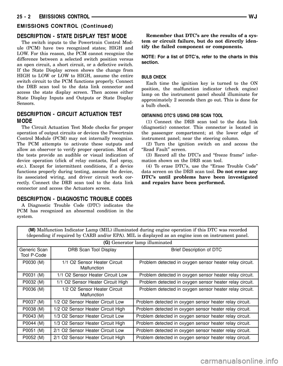
DESCRIPTION - DIAGNOSTIC TROUBLE CODES
A Diagnostic Trouble Code (DTC) indicates the
PCM has recognized an abnormal condition in the
system.Remember that DTC's are the results of a sys-
tem or circuit failure, but do not directly iden-
tify the failed component or components.
NOTE: For a list of DTC's, refer to the charts in this
section.
BULB CHECK
Each time the ignition key is turned to the ON
position, the malfunction indicator (check engine)
lamp on the instrument panel should illuminate for
approximately 2 seconds then go out. This is done for
a bulb check.
OBTAINING DTC'S USING DRB SCAN TOOL
(1) Connect the DRB scan tool to the data link
(diagnostic) connector. This connector is located in
the passenger compartment; at the lower edge of
instrument panel; near the steering column.
(2) Turn the ignition switch on and access the
ªRead Faultº screen.
(3) Record all the DTC's and ªfreeze frameº infor-
mation shown on the DRB scan tool.
(4) To erase DTC's, use the ªErase Trouble Codeº
data screen on the DRB scan tool.Do not erase any
DTC's until problems have been investigated
and repairs have been performed.
(M)Malfunction Indicator Lamp (MIL) illuminated during engine operation if this DTC was recorded
(depending if required by CARB and/or EPA). MIL is displayed as an engine icon on instrument panel.
(G)Generator lamp illuminated
Generic Scan
Tool P-CodeDRB Scan Tool Display Brief Description of DTC
P0030 (M) 1/1 O2 Sensor Heater Circuit
MalfunctionProblem detected in oxygen sensor heater relay circuit.
P0031 (M) 1/1 O2 Sensor Heater Circuit Low Problem detected in oxygen sensor heater relay circuit.
P0032 (M) 1/1 O2 Sensor Heater Circuit High Problem detected in oxygen sensor heater relay circuit.
P0036 (M) 1/2 O2 Sensor Heater Circuit
MalfunctionProblem detected in oxygen sensor heater relay circuit.
P0037 (M) 1/2 O2 Sensor Heater Circuit Low Problem detected in oxygen sensor heater relay circuit.
P0038 (M) 1/2 O2 Sensor Heater Circuit High Problem detected in oxygen sensor heater relay circuit.
P0043 (M) 1/3 O2 Sensor Heater Circuit Low Problem detected in oxygen sensor heater relay circuit.
P0044 (M) 1/3 O2 Sensor Heater Circuit High Problem detected in oxygen sensor heater relay circuit.
P0051 (M) 2/1 O2 Sensor Heater Circuit Low Problem detected in oxygen sensor heater relay circuit.
P0052 (M) 2/1 O2 Sensor Heater Circuit High Problem detected in oxygen sensor heater relay circuit.
25 - 2 EMISSIONS CONTROLWJ
EMISSIONS CONTROL (Continued)
Page 2158 of 2199
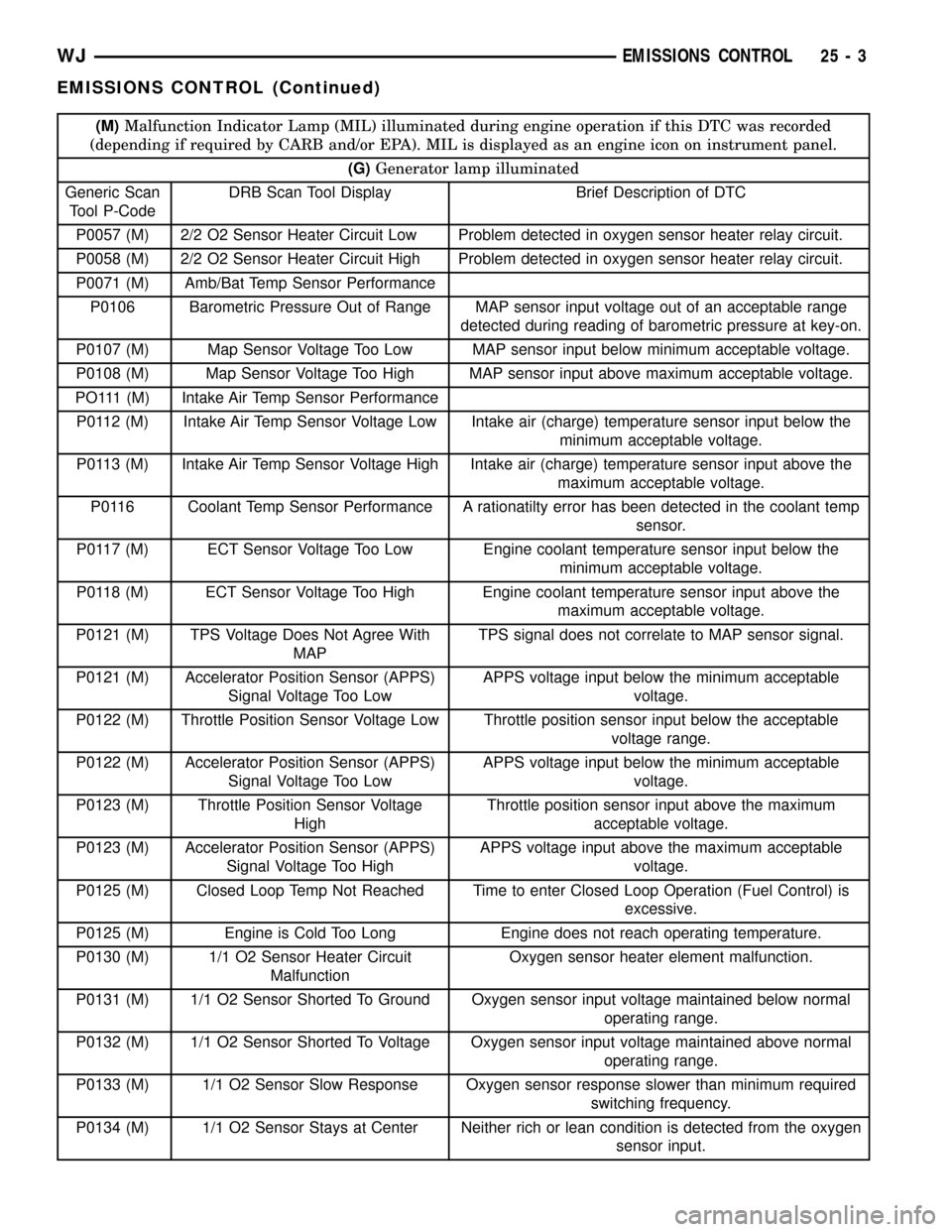
(M)Malfunction Indicator Lamp (MIL) illuminated during engine operation if this DTC was recorded
(depending if required by CARB and/or EPA). MIL is displayed as an engine icon on instrument panel.
(G)Generator lamp illuminated
Generic Scan
Tool P-CodeDRB Scan Tool Display Brief Description of DTC
P0057 (M) 2/2 O2 Sensor Heater Circuit Low Problem detected in oxygen sensor heater relay circuit.
P0058 (M) 2/2 O2 Sensor Heater Circuit High Problem detected in oxygen sensor heater relay circuit.
P0071 (M) Amb/Bat Temp Sensor Performance
P0106 Barometric Pressure Out of Range MAP sensor input voltage out of an acceptable range
detected during reading of barometric pressure at key-on.
P0107 (M) Map Sensor Voltage Too Low MAP sensor input below minimum acceptable voltage.
P0108 (M) Map Sensor Voltage Too High MAP sensor input above maximum acceptable voltage.
PO111 (M) Intake Air Temp Sensor Performance
P0112 (M) Intake Air Temp Sensor Voltage Low Intake air (charge) temperature sensor input below the
minimum acceptable voltage.
P0113 (M) Intake Air Temp Sensor Voltage High Intake air (charge) temperature sensor input above the
maximum acceptable voltage.
P0116 Coolant Temp Sensor Performance A rationatilty error has been detected in the coolant temp
sensor.
P0117 (M) ECT Sensor Voltage Too Low Engine coolant temperature sensor input below the
minimum acceptable voltage.
P0118 (M) ECT Sensor Voltage Too High Engine coolant temperature sensor input above the
maximum acceptable voltage.
P0121 (M) TPS Voltage Does Not Agree With
MAPTPS signal does not correlate to MAP sensor signal.
P0121 (M) Accelerator Position Sensor (APPS)
Signal Voltage Too LowAPPS voltage input below the minimum acceptable
voltage.
P0122 (M) Throttle Position Sensor Voltage Low Throttle position sensor input below the acceptable
voltage range.
P0122 (M) Accelerator Position Sensor (APPS)
Signal Voltage Too LowAPPS voltage input below the minimum acceptable
voltage.
P0123 (M) Throttle Position Sensor Voltage
HighThrottle position sensor input above the maximum
acceptable voltage.
P0123 (M) Accelerator Position Sensor (APPS)
Signal Voltage Too HighAPPS voltage input above the maximum acceptable
voltage.
P0125 (M) Closed Loop Temp Not Reached Time to enter Closed Loop Operation (Fuel Control) is
excessive.
P0125 (M) Engine is Cold Too Long Engine does not reach operating temperature.
P0130 (M) 1/1 O2 Sensor Heater Circuit
MalfunctionOxygen sensor heater element malfunction.
P0131 (M) 1/1 O2 Sensor Shorted To Ground Oxygen sensor input voltage maintained below normal
operating range.
P0132 (M) 1/1 O2 Sensor Shorted To Voltage Oxygen sensor input voltage maintained above normal
operating range.
P0133 (M) 1/1 O2 Sensor Slow Response Oxygen sensor response slower than minimum required
switching frequency.
P0134 (M) 1/1 O2 Sensor Stays at Center Neither rich or lean condition is detected from the oxygen
sensor input.
WJEMISSIONS CONTROL 25 - 3
EMISSIONS CONTROL (Continued)
Page 2161 of 2199
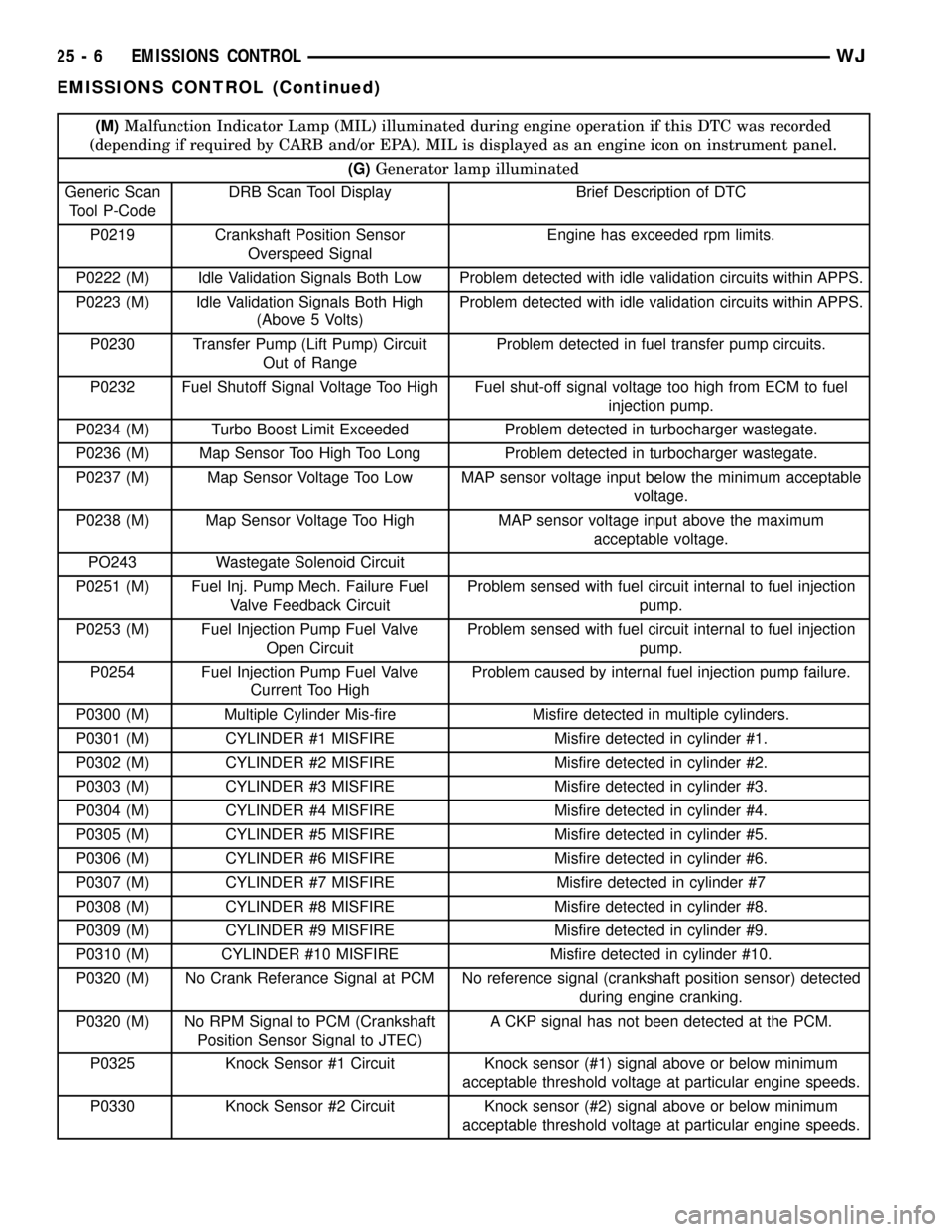
(M)Malfunction Indicator Lamp (MIL) illuminated during engine operation if this DTC was recorded
(depending if required by CARB and/or EPA). MIL is displayed as an engine icon on instrument panel.
(G)Generator lamp illuminated
Generic Scan
Tool P-CodeDRB Scan Tool Display Brief Description of DTC
P0219 Crankshaft Position Sensor
Overspeed SignalEngine has exceeded rpm limits.
P0222 (M) Idle Validation Signals Both Low Problem detected with idle validation circuits within APPS.
P0223 (M) Idle Validation Signals Both High
(Above 5 Volts)Problem detected with idle validation circuits within APPS.
P0230 Transfer Pump (Lift Pump) Circuit
Out of RangeProblem detected in fuel transfer pump circuits.
P0232 Fuel Shutoff Signal Voltage Too High Fuel shut-off signal voltage too high from ECM to fuel
injection pump.
P0234 (M) Turbo Boost Limit Exceeded Problem detected in turbocharger wastegate.
P0236 (M) Map Sensor Too High Too Long Problem detected in turbocharger wastegate.
P0237 (M) Map Sensor Voltage Too Low MAP sensor voltage input below the minimum acceptable
voltage.
P0238 (M) Map Sensor Voltage Too High MAP sensor voltage input above the maximum
acceptable voltage.
PO243 Wastegate Solenoid Circuit
P0251 (M) Fuel Inj. Pump Mech. Failure Fuel
Valve Feedback CircuitProblem sensed with fuel circuit internal to fuel injection
pump.
P0253 (M) Fuel Injection Pump Fuel Valve
Open CircuitProblem sensed with fuel circuit internal to fuel injection
pump.
P0254 Fuel Injection Pump Fuel Valve
Current Too HighProblem caused by internal fuel injection pump failure.
P0300 (M) Multiple Cylinder Mis-fire Misfire detected in multiple cylinders.
P0301 (M) CYLINDER #1 MISFIRE Misfire detected in cylinder #1.
P0302 (M) CYLINDER #2 MISFIRE Misfire detected in cylinder #2.
P0303 (M) CYLINDER #3 MISFIRE Misfire detected in cylinder #3.
P0304 (M) CYLINDER #4 MISFIRE Misfire detected in cylinder #4.
P0305 (M) CYLINDER #5 MISFIRE Misfire detected in cylinder #5.
P0306 (M) CYLINDER #6 MISFIRE Misfire detected in cylinder #6.
P0307 (M) CYLINDER #7 MISFIRE Misfire detected in cylinder #7
P0308 (M) CYLINDER #8 MISFIRE Misfire detected in cylinder #8.
P0309 (M) CYLINDER #9 MISFIRE Misfire detected in cylinder #9.
P0310 (M) CYLINDER #10 MISFIRE Misfire detected in cylinder #10.
P0320 (M) No Crank Referance Signal at PCM No reference signal (crankshaft position sensor) detected
during engine cranking.
P0320 (M) No RPM Signal to PCM (Crankshaft
Position Sensor Signal to JTEC)A CKP signal has not been detected at the PCM.
P0325 Knock Sensor #1 Circuit Knock sensor (#1) signal above or below minimum
acceptable threshold voltage at particular engine speeds.
P0330 Knock Sensor #2 Circuit Knock sensor (#2) signal above or below minimum
acceptable threshold voltage at particular engine speeds.
25 - 6 EMISSIONS CONTROLWJ
EMISSIONS CONTROL (Continued)