2003 JEEP GRAND CHEROKEE wheel bolt torque
[x] Cancel search: wheel bolt torquePage 1250 of 2199
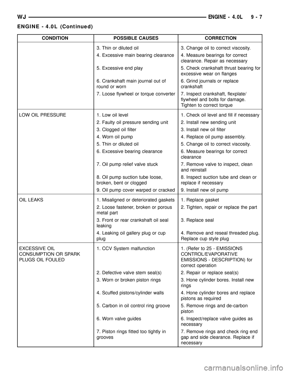
CONDITION POSSIBLE CAUSES CORRECTION
3. Thin or diluted oil 3. Change oil to correct viscosity.
4. Excessive main bearing clearance 4. Measure bearings for correct
clearance. Repair as necessary
5. Excessive end play 5. Check crankshaft thrust bearing for
excessive wear on flanges
6. Crankshaft main journal out of
round or worn6. Grind journals or replace
crankshaft
7. Loose flywheel or torque converter 7. Inspect crankshaft, flexplate/
flywheel and bolts for damage.
Tighten to correct torque
LOW OIL PRESSURE 1. Low oil level 1. Check oil level and fill if necessary
2. Faulty oil pressure sending unit 2. Install new sending unit
3. Clogged oil filter 3. Install new oil filter
4. Worn oil pump 4. Replace oil pump assembly.
5. Thin or diluted oil 5. Change oil to correct viscosity.
6. Excessive bearing clearance 6. Measure bearings for correct
clearance
7. Oil pump relief valve stuck 7. Remove valve to inspect, clean
and reinstall
8. Oil pump suction tube loose,
broken, bent or clogged8. Inspect suction tube and clean or
replace if necessary
9. Oil pump cover warped or cracked 9. Install new oil pump
OIL LEAKS 1. Misaligned or deteriorated gaskets 1. Replace gasket
2. Loose fastener, broken or porous
metal part2. Tighten, repair or replace the part
3. Front or rear crankshaft oil seal
leaking3. Replace seal
4. Leaking oil gallery plug or cup
plug4. Remove and reseal threaded plug.
Replace cup style plug
EXCESSIVE OIL
CONSUMPTION OR SPARK
PLUGS OIL FOULED1. CCV System malfunction 1. (Refer to 25 - EMISSIONS
CONTROL/EVAPORATIVE
EMISSIONS - DESCRIPTION) for
correct operation
2. Defective valve stem seal(s) 2. Repair or replace seal(s)
3. Worn or broken piston rings 3. Hone cylinder bores. Install new
rings
4. Scuffed pistons/cylinder walls 4. Hone cylinder bores and replace
pistons as required
5. Carbon in oil control ring groove 5. Remove rings and de-carbon
piston
6. Worn valve guides 6. Inspect/replace valve guides as
necessary
7. Piston rings fitted too tightly in
grooves7. Remove rings and check ring end
gap and side clearance. Replace if
necessary
WJENGINE - 4.0L 9 - 7
ENGINE - 4.0L (Continued)
Page 1256 of 2199

INSTALLATION
CAUTION: When installing the engine into a vehicle
equipped with an automatic transmission, be care-
ful not to damage the trigger wheel on the engine
flywheel.
(1) Attach a lifting device to the engine and lower
the engine into the engine compartment. For easier
installation, it may be necessary to remove the
engine mount bracket as an aid in alignment of the
engine to the transmission.
(2) Align the transmission torque converter hous-
ing with the engine.
(3) Loosely install the converter housing lower
bolts and install the next higher bolt and nut on each
side.
(4) Tighten all 4 bolts finger tight.
(5) Install the engine mount brackets (if removed).
(6) Lower the engine and engine mount brackets
onto the engine compartment cushions. Install the
bolts and finger tighten the nuts.
(7) Remove the engine lifting device.
(8) Raise and support the vehicle.
(9) Install the remaining engine flywheel/converter
housing bolts. Tighten all bolts to 38 N´m (28 ft. lbs.)
torque.
(10) Install the converter-to-drive plate bolts.
(11) Ensure the installation reference marks are
aligned.
(12) Install the engine flywheel/converter housing
access cover.
(13) Install the exhaust pipe support and tighten
the screw.
(14) Install the engine bending brace (Refer to 9 -
ENGINE/ENGINE BLOCK/STRUCT SUPPORT -
INSTALLATION).
(15) Tighten the engine mount-to-bracket bolts.
(16) Connect the vehicle speed sensor wire connec-
tions and tighten the screws.
(17) Connect the exhaust pipe to the manifold.
(18) Install the engine starter motor (Refer to 8 -
ELECTRICAL/STARTING/STARTER MOTOR -
INSTALLATION).
(19) Connect the wires to the engine starter motor
solenoid.
(20) Lower the vehicle.
(21) Connect all the vacuum hoses and wire con-
nectors identified during engine removal.
(22) Remove protective caps from the power steer-
ing hoses.
(23) Connect the hoses to the fittings at the steer-
ing gear. Tighten the nut to 52 N´m (38 ft. lbs.)
torque.
(24) Fill the pump reservoir with fluid.(25) Inspect the fuel supply line o-ring(s) and
replace if necessary. Connect fuel supply line to injec-
tior rail and verify connection by pulling outward on
the line.
(26) Install the fuel line bracket to the intake
manifold.
(27) Connect the coil rail electrical connectors and
oil pressure switch connector.
(28) Connect the following electrical connectors:
²Power steering pressure switch
²Coolant temperature sensor
²Six (6) fuel injector connectors
²Intake air temperature sensor
²Throttle position sensor
²Map sensor
²Crankshaft position sensor
²Oxygen sensor
²Camshaft position sensor
²Generator connector and B+ terminal wire
(29) Connect all previously removed vacuum hoses.
(30) Connect the body ground strap.
(31) Install the throttle, transmission line pres-
sure, and speed control cables to their mounting
bracket and connect them to the throttle body.
(32) Connect the heater hoses at the engine ther-
mostat housing and water pump.
(33) Install the fan assembly (Refer to 7 - COOL-
ING/ENGINE/RADIATOR FAN - INSTALLATION).
(34) Place the fan shroud in position over the fan.
(35) Install the radiator (Refer to 7 - COOLING/
ENGINE/RADIATOR - INSTALLATION).
(36) Connect the service valves to the A/C com-
pressor ports, if equipped with A/C.
(37) Charge the air conditioner system (Refer to 24
- HEATING & AIR CONDITIONING/PLUMBING -
STANDARD PROCEDURE).
(38) Connect the radiator hoses and automatic
transmission fluid cooler pipes, if equipped.
(39) Install the fan shroud to the radiator or radi-
ator/condenser (if equipped with A/C).
(40) Install upper radiator support.
(41) Connect the upper radiator hose and tighten
the clamp.
(42) Connect the lower radiator hose and tighten
the clamp.
(43) Fill crankcase with engine oil. (Refer to
LUBRICATION & MAINTENANCE/FLUID CAPACI-
TIES - SPECIFICATIONS) for correct capacities.
(44) Fill the cooling system with reusable coolant
or new coolant (Refer to 7 - COOLING - STANDARD
PROCEDURE).
(45) Align the hood to the scribe marks. Install the
hood.
(46) Install the air cleaner assembly.
(47) Install the battery and connect the battery
cable.
WJENGINE - 4.0L 9 - 13
ENGINE - 4.0L (Continued)
Page 1260 of 2199
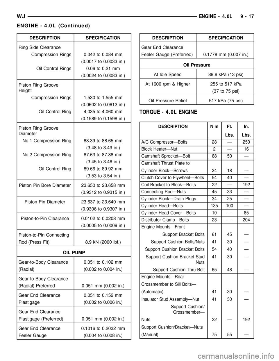
DESCRIPTION SPECIFICATION
Ring Side Clearance
Compression Rings 0.042 to 0.084 mm
(0.0017 to 0.0033 in.)
Oil Control Rings 0.06 to 0.21 mm
(0.0024 to 0.0083 in.)
Piston Ring Groove
Height
Compression Rings 1.530 to 1.555 mm
(0.0602 to 0.0612 in.)
Oil Control Ring 4.035 to 4.060 mm
(0.1589 to 0.1598 in.)
Piston Ring Groove
Diameter
No.1 Compression Ring 88.39 to 88.65 mm
(3.48 to 3.49 in.)
No.2 Compression Ring 87.63 to 87.88 mm
(3.45 to 3.46 in.)
Oil Control Ring 89.66 to 89.92 mm
(3.53 to 3.54 in.)
Piston Pin Bore Diameter 23.650 to 23.658 mm
(0.9312 to 0.9315 in.)
Piston Pin Diameter 23.637 to 23.640 mm
(0.9306 to 0.9307 in.)
Piston-to-Pin Clearance 0.0102 to 0.0208 mm
(0.0005 to 0.0009 in.)
Piston-to-Pin Connecting
Rod (Press Fit) 8.9 kN (2000 lbf.)
OIL PUMP
Gear-to-Body Clearance 0.051 to 0.102 mm
(Radial) (0.002 to 0.004 in.)
Gear-to-Body Clearance
(Radial) Preferred 0.051 mm (0.002 in.)
Gear End Clearance 0.051 to 0.152 mm
Plastigage (0.002 to 0.006 in.)
Gear End Clearance
Plastigage (Preferred) 0.051 mm (0.002 in.)
Gear End Clearance 0.1016 to 0.2032 mm
Feeler Gauge (0.004 to 0.008 in.)DESCRIPTION SPECIFICATION
Gear End Clearance
Feeler Gauge (Preferred) 0.1778 mm (0.007 in.)
Oil Pressure
At Idle Speed 89.6 kPa (13 psi)
At 1600 rpm & Higher 255 to 517 kPa
(37 to 75 psi)
Oil Pressure Relief 517 kPa (75 psi)
TORQUE - 4.0L ENGINE
DESCRIPTION N´m Ft. In.
Lbs. Lbs.
A/C CompressorÐBolts 28 Ð 250
Block HeaterÐNut 2 Ð 16
Camshaft SprocketÐBolt 68 50 Ð
Camshaft Thrust Plate to
Cylinder BlockÐScrews 24 18 Ð
Clutch Cover to FlywheelÐBolts 54 40 Ð
Coil Bracket to BlockÐBolts 22 Ð 192
Connecting RodÐNuts 45 33 Ð
Cylinder BlockÐDrain Plugs 34 25 Ð
Cylinder HeadÐBolts 135 100 Ð
Cylinder Head CoverÐBolts 10 Ð 85
Distributor ClampÐBolts 23 Ð 204
Engine MountsÐFront
Support Bracket Bolts 61 45 Ð
Support Cushion Bolts/Nuts 41 30 Ð
Support Cushion Bracket Bolts 54 40 Ð
Support Cushion Bracket Stud
Nuts41 30 Ð
Support Cushion Thru-Bolt 65 48 Ð
Engine MountsÐRear
Crossmember to Sill BoltsÐ
(Automatic) 41 30 Ð
Insulator Stud AssemblyÐNut 41 30 Ð
Support Cushion/
CrossmemberÐ
Nuts 22 Ð 192
Support Cushion/BracketÐNuts
(Manual) 75 55 Ð
WJENGINE - 4.0L 9 - 17
ENGINE - 4.0L (Continued)
Page 1299 of 2199
(9) Lower the engine until it is properly located on
the engine mounts.
(10) Install the through bolts and tighten the nuts.
(11) Lower the jack stand and remove the piece of
wood.
(12) Install the engine flywheel and transmission
torque converter housing access cover.
(13) Install the engine starter motor. (Refer to 8 -
ELECTRICAL/STARTING/STARTER MOTOR -
INSTALLATION).
(14) Connect the exhaust pipe to the hanger and to
the engine exhaust manifold.
(15) Install transmission oil cooling lines (if
equipped) and oxygen sensor wiring supports that
attach to the oil pan studs.
(16) Install the oil pan drain plug (Fig. 81).
Tighten the plug to 34 N´m (25 ft. lbs.) torque.
(17) Lower the vehicle.
(18) Connect negative cable to battery.
(19) Fill the oil pan with engine oil to the specified
level.
WARNING: USE EXTREME CAUTION WHEN THE
ENGINE IS OPERATING. DO NOT STAND IN A
DIRECT LINE WITH THE FAN. DO NOT PUT YOUR
HANDS NEAR THE PULLEYS, BELTS OR FAN. DO
NOT WEAR LOOSE CLOTHING.
(20) Start the engine and inspect for leaks.
ENGINE OIL PRESSURE
SENSOR
DESCRIPTION
The 3±wire, solid-state engine oil pressure sensor
(sending unit) is located in an engine oil pressure
gallery.
OPERATION
The oil pressure sensor uses three circuits. They
are:
²A 5±volt power supply from the Powertrain Con-
trol Module (PCM)
²A sensor ground through the PCM's sensor
return
²A signal to the PCM relating to engine oil pres-
sure
The oil pressure sensor has a 3±wire electrical
function very much like the Manifold Absolute Pres-
sure (MAP) sensor. Meaning different pressures
relate to different output voltages.
A 5±volt supply is sent to the sensor from the PCM
to power up the sensor. The sensor returns a voltage
signal back to the PCM relating to engine oil pres-
sure. This signal is then transferred (bussed) to theinstrument panel on either a CCD or PCI bus circuit
(depending on vehicle line) to operate the oil pressure
gauge and the check gauges lamp. Ground for the
sensor is provided by the PCM through a low-noise
sensor return.
OIL PUMP
REMOVAL
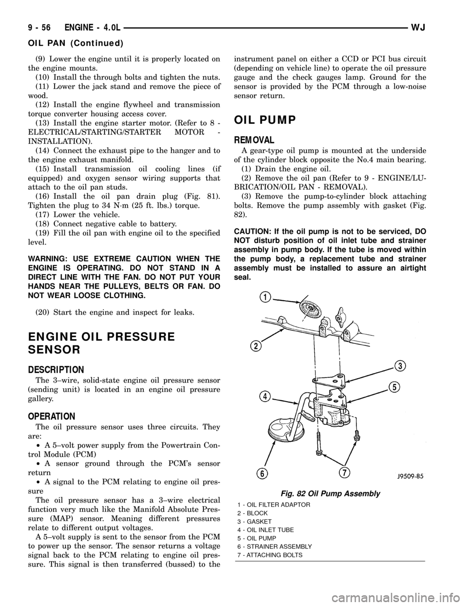
A gear-type oil pump is mounted at the underside
of the cylinder block opposite the No.4 main bearing.
(1) Drain the engine oil.
(2) Remove the oil pan (Refer to 9 - ENGINE/LU-
BRICATION/OIL PAN - REMOVAL).
(3) Remove the pump-to-cylinder block attaching
bolts. Remove the pump assembly with gasket (Fig.
82).
CAUTION: If the oil pump is not to be serviced, DO
NOT disturb position of oil inlet tube and strainer
assembly in pump body. If the tube is moved within
the pump body, a replacement tube and strainer
assembly must be installed to assure an airtight
seal.
Fig. 82 Oil Pump Assembly
1 - OIL FILTER ADAPTOR
2 - BLOCK
3 - GASKET
4 - OIL INLET TUBE
5 - OIL PUMP
6 - STRAINER ASSEMBLY
7 - ATTACHING BOLTS
9 - 56 ENGINE - 4.0LWJ
OIL PAN (Continued)
Page 1342 of 2199
(19) Remove the retaining bolt and the camshaft
drive gear.
CAUTION: Do not allow the engine to rotate. severe
damage to the valve train can occur.
CAUTION: Do not overlook the four smaller bolts at
the front of the cylinder head. Do not attempt to
remove the cylinder head without removing these
four bolts.
CAUTION: Do not hold or pry on the camshaft tar-
get wheel for any reason. A damaged target wheel
can result in a vehicle no start condition.
NOTE: The cylinder head is attached to the cylinder
block with fourteen bolts.
(20) Remove the cylinder head retaining bolts.
(21) Remove the cylinder head and gasket. Discard
the gasket.
CAUTION: Do not lay the cylinder head on its gas-
ket sealing surface, do to the design of the cylinder
head gasket any distortion to the cylinder head
sealing surface may prevent the gasket from prop-
erly sealing resulting in leaks.
CLEANING
To ensure engine gasket sealing, proper surface
preparation must be performed, especially with the
use of aluminum engine components. (Refer to 9 -
ENGINE - STANDARD PROCEDURE)
INSPECTION
(1) Inspect the cylinder head for out-of-flatness,
using a straightedge and a feeler gauge. If tolerances
exceed 0.0508 mm (0.002 in.) replace the cylinder
head.
(2) Inspect the valve seats for damage. Service the
valve seats as necessary.
(3) Inspect the valve guides for wear, cracks or
looseness. If either condition exist, replace the cylin-
der head.
INSTALLATION
NOTE: The cylinder head bolts are tightened using
a torque plus angle procedure. The bolts must be
examined BEFORE reuse. If the threads are necked
down the bolts should be replaced.
Necking can be checked by holding a straight edge
against the threads. If all the threads do not contact
the scale, the bolt should be replaced (Fig. 13).
CAUTION: When cleaning cylinder head and cylin-
der block surfaces, DO NOT use a metal scraper
because the surfaces could be cut or ground. Use
only a wooden or plastic scraper.
(1) Clean the cylinder head and cylinder block
mating surfaces (Refer to 9 - ENGINE - STANDARD
PROCEDURE).
(2) Position the new cylinder head gasket on the
locating dowels.
CAUTION: When installing cylinder head, use care
not damage the tensioner arm or the guide arm.
(3) Position the cylinder head onto the cylinder
block. Make sure the cylinder head seats fully over
the locating dowels.
NOTE: The four smaller cylinder head mounting
bolts require sealant to be added to them before
installing. Failure to do so may cause leaks.
(4) Lubricate the cylinder head bolt threads with
clean engine oil and install the ten M10 bolts.
(5) Coat the four M8 cylinder head bolts with
Mopar Lock and Seal Adhesivethen install the
bolts.
NOTE: The cylinder head bolts are tightened using
an angle torque procedure, however, the bolts are
not a torque-to-yield design.
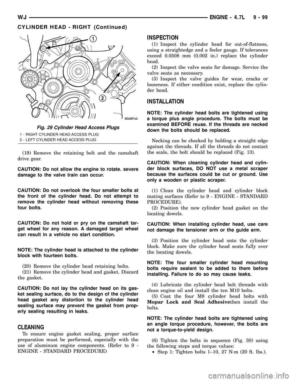
(6) Tighten the bolts in sequence (Fig. 30) using
the following steps and torque values:
²Step 1: Tighten bolts 1±10, 27 N´m (20 ft. lbs.).
Fig. 29 Cylinder Head Access Plugs
1 - RIGHT CYLINDER HEAD ACCESS PLUG
2 - LEFT CYLINDER HEAD ACCESS PLUG
WJENGINE - 4.7L 9 - 99
CYLINDER HEAD - RIGHT (Continued)
Page 1356 of 2199
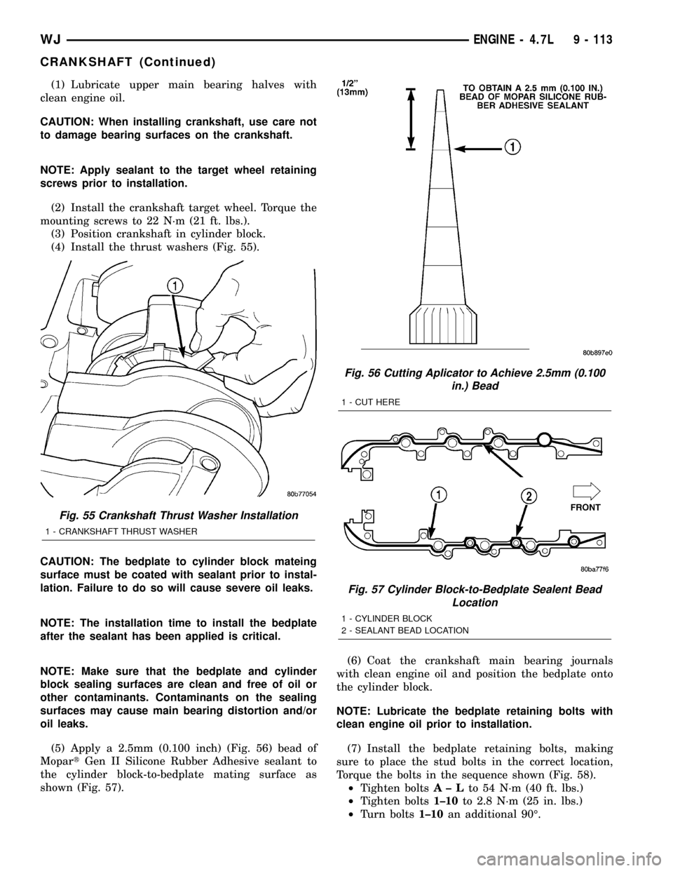
(1) Lubricate upper main bearing halves with
clean engine oil.
CAUTION: When installing crankshaft, use care not
to damage bearing surfaces on the crankshaft.
NOTE: Apply sealant to the target wheel retaining
screws prior to installation.
(2) Install the crankshaft target wheel. Torque the
mounting screws to 22 N´m (21 ft. lbs.).
(3) Position crankshaft in cylinder block.
(4) Install the thrust washers (Fig. 55).
CAUTION: The bedplate to cylinder block mateing
surface must be coated with sealant prior to instal-
lation. Failure to do so will cause severe oil leaks.
NOTE: The installation time to install the bedplate
after the sealant has been applied is critical.
NOTE: Make sure that the bedplate and cylinder
block sealing surfaces are clean and free of oil or
other contaminants. Contaminants on the sealing
surfaces may cause main bearing distortion and/or
oil leaks.
(5) Apply a 2.5mm (0.100 inch) (Fig. 56) bead of
MopartGen II Silicone Rubber Adhesive sealant to
the cylinder block-to-bedplate mating surface as
shown (Fig. 57).(6) Coat the crankshaft main bearing journals
with clean engine oil and position the bedplate onto
the cylinder block.
NOTE: Lubricate the bedplate retaining bolts with
clean engine oil prior to installation.
(7) Install the bedplate retaining bolts, making
sure to place the stud bolts in the correct location,
Torque the bolts in the sequence shown (Fig. 58).
²Tighten boltsA± Lto 54 N´m (40 ft. lbs.)
²Tighten bolts1±10to 2.8 N´m (25 in. lbs.)
²Turn bolts1±10an additional 90É.
Fig. 55 Crankshaft Thrust Washer Installation
1 - CRANKSHAFT THRUST WASHER
Fig. 56 Cutting Aplicator to Achieve 2.5mm (0.100
in.) Bead
1 - CUT HERE
Fig. 57 Cylinder Block-to-Bedplate Sealent Bead
Location
1 - CYLINDER BLOCK
2 - SEALANT BEAD LOCATION
WJENGINE - 4.7L 9 - 113
CRANKSHAFT (Continued)
Page 1412 of 2199
FRAME & BUMPERS
TABLE OF CONTENTS
page page
FRONT ABSORBER
REMOVAL.............................1
INSTALLATION..........................1
FRONT FASCIA
REMOVAL.............................1
INSTALLATION..........................1
REAR ABSORBER
REMOVAL.............................2
INSTALLATION..........................2
REAR FASCIA
REMOVAL.............................2
INSTALLATION..........................4
FRAME
SPECIFICATIONS
SPECIFICATIONS - TORQUE.............4
FRAME DIMENSIONS...................4
FRONT SKID PLATE
REMOVAL.............................7INSTALLATION..........................7
FRONT TOW HOOK
REMOVAL.............................7
INSTALLATION..........................7
FUEL TANK SKID PLATE
DESCRIPTION..........................7
REAR TOW HOOK
REMOVAL.............................7
INSTALLATION..........................7
TRAILER HITCH
REMOVAL.............................8
INSTALLATION..........................8
TRANSFER CASE SKID PLATE
REMOVAL.............................8
INSTALLATION..........................8
FRONT ABSORBER
REMOVAL
(1) Remove front fascia, refer to (Refer to 13 -
FRAMES & BUMPERS/BUMPERS/FRONT FASCIA
- REMOVAL).
(2) Remove the retainer attaching the absorber to
the fascia.
(3) Separate the absorber from the fascia.
INSTALLATION
(1) Position the absorber on the fascia.
(2) Install the retainer attaching the absorber to
the fascia.
(3) Install front fascia. Refer to (Refer to 13 -
FRAMES & BUMPERS/BUMPERS/FRONT FASCIA
- INSTALLATION).
FRONT FASCIA
REMOVAL
(1) Raise and support vehicle.
(2) Turn front wheels to access rivets and remove
plastic rivets attaching fascia to wheel liner.
(3) Remove bolts attaching fascia to fender (Fig. 1).(4) Remove plastic push pin fasteners attaching
front fascia to lower radiator crossmember splash
shield (Fig. 2).
(5) Disengage fog lamp connectors, if equipped.
(6) Remove screws attaching fascia/grille to upper
radiator crossmember (Fig. 3).
(7) Slide fascia forward to separate from vehicle.
INSTALLATION
(1) Slide fascia onto vehicle engaging fascia with
tabs on bottom of front fenders.
(2) Install screws attaching fascia/grille to upper
radiator crossmember (Fig. 3).
(3) Install bolts attaching fascia to fender (Fig. 1).
(4) Engage fog lamp connectors, if equipped.
(5) Install plastic rivets attaching fascia to wheel
liner.
(6) Install plastic push pin fasteners attaching
front fascia to lower radiator crossmember splash
shield (Fig. 2).
(7) Remove supports and lower vehicle.
WJFRAME & BUMPERS 13 - 1
Page 1415 of 2199
INSTALLATION
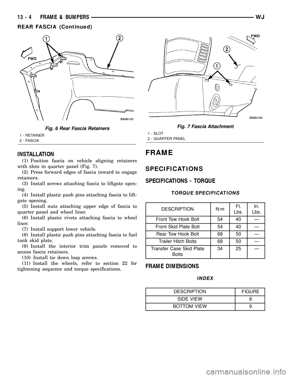
(1) Position fascia on vehicle aligning retainers
with slots in quarter panel (Fig. 7).
(2) Press forward edges of fascia inward to engage
retainers.
(3) Install screws attaching fascia to liftgate open-
ing.
(4) Install plastic push pins attaching fascia to lift-
gate opening.
(5) Install nuts attaching upper edge of fascia to
quarter panel and wheel liner.
(6) Install plastic rivets attaching fascia to wheel
liner.
(7) Install support lower vehicle.
(8) Install plastic push pins attaching fascia to fuel
tank skid plate.
(9) Install the interior trim panels removed to
access fascia retainers.
(10) Install tie down loop screws.
(11) Install the wheels, refer to section 22 for
tightening sequence and torque specifications.
FRAME
SPECIFICATIONS
SPECIFICATIONS - TORQUE
TORQUE SPECIFICATIONS
DESCRIPTION N´mFt.
Lbs.In.
Lbs.
Front Tow Hook Bolt 54 40 Ð
Front Skid Plate Bolt 54 40 Ð
Rear Tow Hook Bolt 68 50 Ð
Trailer Hitch Bolts 68 50 Ð
Transfer Case Skid Plate
Bolts34 25 Ð
FRAME DIMENSIONS
INDEX
DESCRIPTION FIGURE
SIDE VIEW 8
BOTTOM VIEW 9
Fig. 6 Rear Fascia Retainers
1 - RETAINER
2 - FASCIA
Fig. 7 Fascia Attachment
1 - SLOT
2 - QUARTER PANEL
13 - 4 FRAME & BUMPERSWJ
REAR FASCIA (Continued)