2003 JEEP GRAND CHEROKEE pump - standard procedure
[x] Cancel search: pump - standard procedurePage 278 of 2199
TRANSMISSION
TABLE OF CONTENTS
page page
TRANS COOLER
DESCRIPTION.........................55STANDARD PROCEDURE - FLUSHING
COOLERS AND TUBES.................55
TRANS COOLER
DESCRIPTION
An internal high capacity/high efficiency cooler is
used on all vehicles these coolers are an oil-to-coolant
type which consists of plates mounted in the radiator
outlet tank (Fig. 36). Because the internal oil cooler
is so efficient, no auxiliary oil cooler is offered The
cooler is not servicable seperatly from the radiator.
STANDARD PROCEDURE - FLUSHING
COOLERS AND TUBES
When a transmission failure has contaminated the
fluid, the oil cooler(s) must be flushed. The torque
converter must also be replaced. This will insure that
metal particles or sludged oil are not later trans-
ferred back into the reconditioned (or replaced) trans-
mission.
The only recommended procedure for flushing cool-
ers and lines is to use Tool 6906-B Cooler Flusher.
WARNING: WEAR PROTECTIVE EYEWEAR THAT
MEETS THE REQUIREMENTS OF OSHA AND ANSI
Z87.1±1968. WEAR STANDARD INDUSTRIAL RUB-
BER GLOVES.
KEEP LIGHTED CIGARETTES, SPARKS, FLAMES,
AND OTHER IGNITION SOURCES AWAY FROM THE
AREA TO PREVENT THE IGNITION OF COMBUSTI-
BLE LIQUIDS AND GASES. KEEP A CLASS (B) FIRE
EXTINGUISHER IN THE AREA WHERE THE
FLUSHER WILL BE USED.
KEEP THE AREA WELL VENTILATED.
DO NOT LET FLUSHING SOLVENT COME IN CON-
TACT WITH YOUR EYES OR SKIN: IF EYE CONTAM-
INATION OCCURS, FLUSH EYES WITH WATER FOR
15 TO 20 SECONDS. REMOVE CONTAMINATED
CLOTHING AND WASH AFFECTED SKIN WITH
SOAP AND WATER. SEEK MEDICAL ATTENTION.
(1) Remove cover plate filler plug on Tool 6906-B.
Fill reservoir 1/2 to 3/4 full of fresh flushing solution.
Flushing solvents are petroleum based solutions gen-
erally used to clean automatic transmission compo-
nents.DO NOTuse solvents containing acids, water,
gasoline, or any other corrosive liquids.(2) Reinstall filler plug on Tool 6906-B.
(3) Verify pump power switch is turned OFF. Con-
nect red alligator clip to positive (+) battery post.
Connect black (-) alligator clip to a good ground.
(4) Disconnect the cooler lines at the transmission.
NOTE: When flushing transmission cooler and
lines, ALWAYS reverse flush.
NOTE: The converter drainback valve must be
removed and an appropriate replacement hose
installed to bridge the space between the transmis-
sion cooler line and the cooler fitting. Failure to
remove the drainback valve will prevent reverse
flushing the system. A suitable replacement hose
can be found in the adapter kit supplied with the
flushing tool.
(5) Connect the BLUE pressure line to the OUT-
LET (From) cooler line.
(6) Connect the CLEAR return line to the INLET
(To) cooler line
(7) Turn pump ON for two to three minutes to
flush cooler(s) and lines.
(8) Turn pump OFF.
(9) Disconnect CLEAR suction line from reservoir
at cover plate. Disconnect CLEAR return line at
cover plate, and place it in a drain pan.
(10) Turn pump ON for 30 seconds to purge flush-
ing solution from cooler and lines. Turn pump OFF.
(11) Place CLEAR suction line into a one quart
container of MopartATF +4, type 9602, Automatic
Transmission Fluid.
(12) Turn pump ON until all transmission fluid is
removed from the one quart container and lines. This
purges any residual cleaning solvent from the trans-
mission cooler and lines. Turn pump OFF.
(13) Disconnect alligator clips from battery. Recon-
nect flusher lines to cover plate, and remove flushing
adapters from cooler lines.
WJTRANSMISSION 7 - 55
Page 610 of 2199

²Front Check Valve- The front washer system
check valve is integral to the wye fitting located in
the washer plumbing between the cowl plenum
washer hose and the front washer nozzles, and is
concealed beneath the cowl plenum cover/grille panel
at the base of the windshield.
²Front Washer Nozzle- Two fluidic front
washer nozzles are secured with integral snap fea-
tures to dedicated openings in the cowl plenum cover/
grille panel located near the base of the windshield.
²Front Washer Plumbing- The plumbing for
the front washer system consists of rubber hoses and
molded plastic fittings. The plumbing is routed along
the left side of the engine compartment from the
washer reservoir, and through the dash panel into
the cowl plenum to the front washer nozzle fittings
beneath the cowl plenum cover/grille panel.
²Front Washer Pump/Motor- The front washer
pump/motor unit is located in a dedicated hole on the
lower outboard side of the washer reservoir, behind
the inner fender liner ahead of the left front wheel.
The front washer pump is located ahead of and below
the rear washer pump.
²Front Wiper Arm- The two front wiper arms
are secured with nuts to the threaded studs on the
ends of the two wiper pivot shafts, which extend
through the cowl plenum cover/grille panel located
near the base of the windshield.
²Front Wiper Blade- The two front wiper
blades are secured to the two front wiper arms with
an integral latch, and are parked on the glass near
the bottom of the windshield when the front wiper
system is not in operation.
²Front Wiper Module- The front wiper pivot
shafts are the only visible components of the front
wiper module. The remainder of the module is con-
cealed within the cowl plenum beneath the cowl ple-
num cover/grille panel. The front wiper module
includes the module bracket, four rubber-isolated
wiper module mounts, the front wiper motor, the
wiper motor crank arm, the two wiper drive links,
and the two front wiper pivots.
²Rain Sensor Module- Models equipped with
the optional automatic wiper feature have a Rain
Sensor Module (RSM) located behind a trim cover on
a bracket bonded to the inside surface of the wind-
shield glass, just above the inside rear view mirror
mounting button.
²Right Multi-Function Switch- The right
(wiper) multi-function switch is secured to the right
side of the multi-function switch mounting housing
near the top of the steering column, just below the
steering wheel. Only the control stalk for the right
multi-function switch is visible, while the remainder
of the switch is concealed beneath the steering col-
umn shrouds. The right multi-function switch con-tains all of the switches and control circuitry for both
the front and rear wiper and washer systems.
²Washer Fluid Level Switch- The washer fluid
level switch is located in a dedicated hole near the
center of the forward surface of the washer reservoir,
behind the left front wheel house splash shield.
²Washer Reservoir- The washer reservoir is
concealed between the left inner fender shield and
the left outer fender panel, behind the inner fender
liner and ahead of the left front wheel. The washer
reservoir filler neck is the only visible portion of the
reservoir, and it is accessed from the left front corner
of the engine compartment.
²Wiper High-Low Relay- The wiper high-low
relay is an International Standards Organization
(ISO) micro relay located in the Power Distribution
Center (PDC) in the engine compartment near the
battery.
²Wiper On-Off Relay- The wiper on-off relay is
an International Standards Organization (ISO) micro
relay located in the Power Distribution Center (PDC)
in the engine compartment near the battery.
Hard wired circuitry connects the front wiper and
washer system components to the electrical system of
the vehicle. These hard wired circuits are integral to
several wire harnesses, which are routed throughout
the vehicle and retained by many different methods.
These circuits may be connected to each other, to the
vehicle electrical system and to the front wiper and
washer system components through the use of a com-
bination of soldered splices, splice block connectors,
and many different types of wire harness terminal
connectors and insulators. Refer to the appropriate
wiring information. The wiring information includes
wiring diagrams, proper wire and connector repair
procedures, further details on wire harness routing
and retention, as well as pin-out and location views
for the various wire harness connectors, splices and
grounds.
OPERATING MODES
The components of the front wiper and washer sys-
tem are designed to work in concert to provide the
following operating modes:
²Automatic Wiper- In models equipped with
the optional automatic wiper feature, the internal
circuitry of both the right (wiper) multi-function
switch, the rain sensor module, and the BCM work
in concert to provide an automatic wiper mode with
five sensitivity selections. The BCM tells the Rain
Sensor Module (RSM) when the automatic wiper
mode is selected and the manually selected sensitiv-
ity level, then the rain sensor module tells the BCM
each time enough water droplets have accumulated
within the wipe pattern on the windshield to require
front wiper operation. The BCM then automatically
WJFRONT WIPERS/WASHERS 8R - 3
FRONT WIPERS/WASHERS (Continued)
Page 1245 of 2199
REMOVAL
REMOVAL - CAMSHAFT BEARINGS.......31
REMOVAL - CAMSHAFT................31
INSPECTION
INSPECTION - CAMSHAFT BEARINGS.....31
INSPECTION - CAMSHAFT..............31
INSTALLATION
INSTALLATION - CAMSHAFT BEARINGS . . . 32
INSTALLATION - CAMSHAFT............32
CONNECTING ROD BEARINGS
STANDARD PROCEDURE - FITTING
CONNECTING ROD BEARINGS..........33
CRANKSHAFT
DESCRIPTION.........................35
CRANKSHAFT MAIN BEARINGS
STANDARD PROCEDURE - FITTING
CRANKSHAFT MAIN BEARINGS..........36
REMOVAL.............................39
INSPECTION..........................40
INSTALLATION.........................40
CRANKSHAFT OIL SEAL - FRONT
REMOVAL.............................41
INSTALLATION.........................41
CRANKSHAFT OIL SEAL - REAR
REMOVAL.............................42
INSTALLATION.........................42
HYDRAULIC LIFTERS
DESCRIPTION.........................43
REMOVAL.............................43
CLEANING............................43
INSPECTION..........................43
INSTALLATION.........................43
PISTON & CONNECTING ROD
DESCRIPTION.........................44
STANDARD PROCEDURE - PISTON FITTING . 44
REMOVAL.............................45
INSTALLATION.........................46
PISTON RINGS
STANDARD PROCEDURE - PISTON RING
FITTING.............................47
VIBRATION DAMPER
REMOVAL.............................49
INSTALLATION.........................49STRUCTURAL SUPPORT
REMOVAL.............................49
INSTALLATION.........................50
LUBRICATION
DESCRIPTION.........................50
OPERATION...........................50
DIAGNOSIS AND TESTING
DIAGNOSIS AND TESTING - ENGINE OIL
PRESSURE..........................51
DIAGNOSIS AND TESTING - ENGINE OIL
LEAK...............................51
OIL
STANDARD PROCEDURE - ENGINE OIL
SERVICE............................53
OIL FILTER
REMOVAL.............................53
INSTALLATION.........................54
OIL PAN
DESCRIPTION.........................54
REMOVAL.............................54
INSTALLATION.........................55
ENGINE OIL PRESSURE SENSOR
DESCRIPTION.........................56
OPERATION...........................56
OIL PUMP
REMOVAL.............................56
INSTALLATION.........................57
INTAKE MANIFOLD
DESCRIPTION.........................57
DIAGNOSIS AND TESTING - INTAKE
MANIFOLD LEAKAGE..................57
REMOVAL.............................57
INSTALLATION.........................57
EXHAUST MANIFOLD
DESCRIPTION.........................58
REMOVAL.............................58
INSTALLATION.........................58
TIMING BELT / CHAIN COVER(S)
REMOVAL.............................58
INSTALLATION.........................58
TIMING BELT/CHAIN AND SPROCKETS
REMOVAL.............................60
INSTALLATION.........................60
ENGINE - 4.0L
DESCRIPTION
The 4.0 Liter (242 CID) six-cylinder engine is an
In-line, lightweight, overhead valve engine. This
engine is designed for unleaded fuel.
The engine cylinder head has dual quench-type
combustion chambers that create turbulence and fast
burning of the air/fuel mixture. This results in better
fuel economy.
The cylinders are numbered 1 through 6 from front
to rear. The firing order is 1-5-3-6-2-4 (Fig. 1).The crankshaft rotation is clockwise, when viewed
from the front of the engine. The crankshaft rotates
within seven main bearings. The camshaft rotates
within four bearings.
The engine Build Date Code is located on a
machined surface on the right side of the cylinder
block between the No.2 and No.3 cylinders (Fig. 2).
The digits of the code identify:
²1st DigitÐThe year (8 = 1998).
²2nd & 3rd DigitsÐThe month (01 - 12).
²4th & 5th DigitsÐThe engine type/fuel system/
compression ratio (MX = A 4.0 Liter (242 CID) 8.7:1
compression ratio engine with a multi-point fuel
injection system).
9 - 2 ENGINE - 4.0LWJ
Page 1247 of 2199
DIAGNOSIS AND TESTING - ENGINE DIAGNOSIS - PERFORMANCE
ENGINE PERFORMANCE DIAGNOSIS CHART
CONDITION POSSIBLE CAUSES CORRECTION
ENGINE WILL NOT CRANK 1. Weak or dead battery 1. Charge/Replace Battery. (Refer to
8 - ELECTRICAL/BATTERY
SYSTEM/BATTERY - STANDARD
PROCEDURE), for correct
procedures. Check charging system.
(Refer to 8 - ELECTRICAL/
CHARGING - DIAGNOSIS AND
TESTING), for correct procedures.
2. Corroded or loose battery
connections2. Clean/tighten suspect battery/
starter connections
3. Faulty starter or related circuit(s) 3. Check starting system. (Refer to 8
- ELECTRICAL/STARTING -
DIAGNOSIS AND TESTING), for
correct diagnostics/procedures
4. Siezed accessory drive
component4. Remove accessory drive belt and
attempt to start engine. If engine
starts, repair/replace siezed
component.
5. Engine internal mechanical failure
or hydro-static lock5. (Refer to 9 - ENGINE -
DIAGNOSIS AND TESTING), for
correct diagnostics/procedures
ENGINE CRANKS BUT WILL
NOT START1. No spark 1. Check for spark. (Refer to 8 -
ELECTRICAL/IGNITION CONTROL -
SPECIFICATIONS), for correct
procedures.
2. No fuel 2. Perform fuel pressure test (Refer
to 14 - FUEL SYSTEM/FUEL
DELIVERY/FUEL PUMP -
DIAGNOSIS AND TESTING), and if
necessary, inspect fuel injector(s) and
driver circuits. (Refer to 14 - FUEL
SYSTEM/FUEL INJECTION/FUEL
INJECTOR - DIAGNOSIS AND
TESTING), for correct procedures.
3. Low or no engine compression 3. Perform cylinder compression
pressure test. (Refer to 9 - ENGINE -
DIAGNOSIS AND TESTING).
ENGINE LOSS OF POWER 1. Worn or burned distributor rotor 1. Install new distributor rotor
2. Worn camshaft position sensor
shaft2. Remove and repair camshaft
position sensor.(Refer to 8 -
ELECTRICAL/IGNITION CONTROL/
CAMSHAFT POSITION SENSOR -
REMOVAL).
9 - 4 ENGINE - 4.0LWJ
ENGINE - 4.0L (Continued)
Page 1255 of 2199

(7) Remove the fan assembly from the water pump
(Refer to 7 - COOLING/ENGINE/RADIATOR FAN -
REMOVAL).
(8) Remove the fan shroud.
(9) Disconnect the transmission fluid cooler lines
(automatic transmission).
(10) Discharge the A/C system (Refer to 24 -
HEATING & AIR CONDITIONING/PLUMBING -
STANDARD PROCEDURE).
(11) Remove the service valves and cap the com-
pressor ports.
(12) Remove the radiator or radiator/condenser (if
equipped with A/C).
(13) Disconnect the heater hoses at the engine
thermostat housing and water pump.
(14) Disconnect the accelerator cable, transmission
line pressure cable and speed control cable (if
equipped) from the throttle body.
(15) Remove cables from the bracket and secure
out of the way.
(16) Disconnect the body ground at the engine.
(17) Disconnect the following connectors and
secure their harness out of the way.
²Power steering pressure switch
²Coolant temperature sensor
²Six (6) fuel injector connectors
²Intake air temperature sensor
²Throttle position sensor
²Map sensor
²Crankshaft position sensor
²Oxygen sensor
²Camshaft position sensor
²Generator connector and B+ terminal wire
(18) Disconnect the coil rail electrical connections
and the oil pressure switch connector.
(19) Perform the fuel pressure release procedure
(Refer to 14 - FUEL SYSTEM/FUEL DELIVERY -
STANDARD PROCEDURE).
(20) Disconnect the fuel supply line at the injector
rail (Refer to 14 - FUEL SYSTEM/FUEL DELIVERY/
QUICK CONNECT FITTING - STANDARD PROCE-
DURE).
(21) Remove the fuel line bracket from the intake
manifold.
(22) Remove the air cleaner assembly (Fig. 5).
(23) Disconnect the hoses from the fittings at the
steering gear.
(24) Drain the pump reservoir.
(25) Cap the fittings on the hoses and steering
gear to prevent foreign objects from entering the sys-
tem.
(26) Raise and support the vehicle.
(27) Disconnect the wires from the engine starter
motor solenoid.(28) Remove the engine starter motor (Refer to 8 -
ELECTRICAL/STARTING/STARTER MOTOR -
REMOVAL).
(29) Disconnect the oxygen sensor from the
exhaust pipe.
(30) Disconnect the exhaust pipe from the mani-
fold.
(31) Remove the exhaust pipe support.
(32) Remove the bending brace (Refer to 9 -
ENGINE/ENGINE BLOCK/STRUCT SUPPORT -
REMOVAL).
(33) Remove the engine flywheel/converter housing
access cover.
(34) Mark the converter and drive plate location.
(35) Remove the converter-to-drive plate bolts.
(36) Remove the upper engine flywheel/converter
housing bolts and loosen the bottom bolts.
(37) Remove the engine mount cushion-to-engine
compartment bracket bolts.
(38) Lower the vehicle.
(39) Attach a lifting device to the engine.
(40) Raise the engine off the front supports.
(41) Place a support or floor jack under the con-
verter (or engine flywheel) housing.
(42) Remove the remaining converter (or engine
flywheel) housing bolts.
(43) Lift the engine out of the engine compart-
ment.
Fig. 5 Air Cleaner Assembly
1 - POWER STEERING PUMP
2 - AIR CLEANER ASSEMBLY
9 - 12 ENGINE - 4.0LWJ
ENGINE - 4.0L (Continued)
Page 1256 of 2199

INSTALLATION
CAUTION: When installing the engine into a vehicle
equipped with an automatic transmission, be care-
ful not to damage the trigger wheel on the engine
flywheel.
(1) Attach a lifting device to the engine and lower
the engine into the engine compartment. For easier
installation, it may be necessary to remove the
engine mount bracket as an aid in alignment of the
engine to the transmission.
(2) Align the transmission torque converter hous-
ing with the engine.
(3) Loosely install the converter housing lower
bolts and install the next higher bolt and nut on each
side.
(4) Tighten all 4 bolts finger tight.
(5) Install the engine mount brackets (if removed).
(6) Lower the engine and engine mount brackets
onto the engine compartment cushions. Install the
bolts and finger tighten the nuts.
(7) Remove the engine lifting device.
(8) Raise and support the vehicle.
(9) Install the remaining engine flywheel/converter
housing bolts. Tighten all bolts to 38 N´m (28 ft. lbs.)
torque.
(10) Install the converter-to-drive plate bolts.
(11) Ensure the installation reference marks are
aligned.
(12) Install the engine flywheel/converter housing
access cover.
(13) Install the exhaust pipe support and tighten
the screw.
(14) Install the engine bending brace (Refer to 9 -
ENGINE/ENGINE BLOCK/STRUCT SUPPORT -
INSTALLATION).
(15) Tighten the engine mount-to-bracket bolts.
(16) Connect the vehicle speed sensor wire connec-
tions and tighten the screws.
(17) Connect the exhaust pipe to the manifold.
(18) Install the engine starter motor (Refer to 8 -
ELECTRICAL/STARTING/STARTER MOTOR -
INSTALLATION).
(19) Connect the wires to the engine starter motor
solenoid.
(20) Lower the vehicle.
(21) Connect all the vacuum hoses and wire con-
nectors identified during engine removal.
(22) Remove protective caps from the power steer-
ing hoses.
(23) Connect the hoses to the fittings at the steer-
ing gear. Tighten the nut to 52 N´m (38 ft. lbs.)
torque.
(24) Fill the pump reservoir with fluid.(25) Inspect the fuel supply line o-ring(s) and
replace if necessary. Connect fuel supply line to injec-
tior rail and verify connection by pulling outward on
the line.
(26) Install the fuel line bracket to the intake
manifold.
(27) Connect the coil rail electrical connectors and
oil pressure switch connector.
(28) Connect the following electrical connectors:
²Power steering pressure switch
²Coolant temperature sensor
²Six (6) fuel injector connectors
²Intake air temperature sensor
²Throttle position sensor
²Map sensor
²Crankshaft position sensor
²Oxygen sensor
²Camshaft position sensor
²Generator connector and B+ terminal wire
(29) Connect all previously removed vacuum hoses.
(30) Connect the body ground strap.
(31) Install the throttle, transmission line pres-
sure, and speed control cables to their mounting
bracket and connect them to the throttle body.
(32) Connect the heater hoses at the engine ther-
mostat housing and water pump.
(33) Install the fan assembly (Refer to 7 - COOL-
ING/ENGINE/RADIATOR FAN - INSTALLATION).
(34) Place the fan shroud in position over the fan.
(35) Install the radiator (Refer to 7 - COOLING/
ENGINE/RADIATOR - INSTALLATION).
(36) Connect the service valves to the A/C com-
pressor ports, if equipped with A/C.
(37) Charge the air conditioner system (Refer to 24
- HEATING & AIR CONDITIONING/PLUMBING -
STANDARD PROCEDURE).
(38) Connect the radiator hoses and automatic
transmission fluid cooler pipes, if equipped.
(39) Install the fan shroud to the radiator or radi-
ator/condenser (if equipped with A/C).
(40) Install upper radiator support.
(41) Connect the upper radiator hose and tighten
the clamp.
(42) Connect the lower radiator hose and tighten
the clamp.
(43) Fill crankcase with engine oil. (Refer to
LUBRICATION & MAINTENANCE/FLUID CAPACI-
TIES - SPECIFICATIONS) for correct capacities.
(44) Fill the cooling system with reusable coolant
or new coolant (Refer to 7 - COOLING - STANDARD
PROCEDURE).
(45) Align the hood to the scribe marks. Install the
hood.
(46) Install the air cleaner assembly.
(47) Install the battery and connect the battery
cable.
WJENGINE - 4.0L 9 - 13
ENGINE - 4.0L (Continued)
Page 1263 of 2199
(2) Drain the coolant (Refer to 7 - COOLING -
STANDARD PROCEDURE) and disconnect the hoses
at the engine thermostat housing and the water
pump inlet. DO NOT waste reusable coolant. If the
solution is clean and is being drained only to service
the engine or cooling system, drain the coolant into a
clean container for reuse.
(3) Remove the air cleaner assembly (Refer to 9 -
ENGINE/AIR INTAKE SYSTEM/AIR CLEANER
HOUSING - REMOVAL).
(4) Remove the cylinder head cover (Refer to 9 -
ENGINE/CYLINDER HEAD/CYLINDER HEAD
COVER(S) - REMOVAL).
(5) Remove the capscrews, bridge and pivot assem-
blies and rocker arms (Refer to 9 - ENGINE/CYLIN-
DER HEAD/ROCKER ARM / ADJUSTER ASSY -
REMOVAL).
(6) Remove the push rods.Retain the push rods,
bridges, pivots and rocker arms in the same
order as removed.
(7) Remove the accessory drive belt (Refer to 7 -
COOLING/ACCESSORY DRIVE/DRIVE BELTS -
REMOVAL).
(8) Remove the A/C compressor mounting bolts
and secure the compressor to the side.
(9) Remove the power steering pump and bracket
from the intake manifold and water pump. Set the
pump and bracket aside. DO NOT disconnect the
hoses.
(10) Perform the Fuel System Pressure Release
procedure. (Refer to 14 - FUEL SYSTEM/FUEL
DELIVERY - STANDARD PROCEDURE).
(11) Disconnect the fuel supply line at the fuel rail.(12) Remove the intake and exhaust manifolds
from the engine cylinder head (Refer to 9 - ENGINE/
MANIFOLDS/INTAKE MANIFOLD - REMOVAL).
(13) Remove the coil rail (Refer to 8 - ELECTRI-
CAL/IGNITION CONTROL/COIL RAIL - REMOV-
AL).
(14) Remove spark plugs (Refer to 8 - ELECTRI-
CAL/IGNITION CONTROL/SPARK PLUG - REMOV-
AL).
(15) Disconnect the temperature sending unit wire
connector.
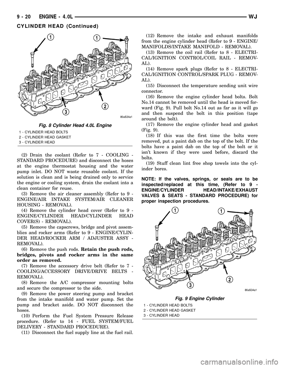
(16) Remove the engine cylinder head bolts. Bolt
No.14 cannot be removed until the head is moved for-
ward (Fig. 9). Pull bolt No.14 out as far as it will go
and then suspend the bolt in this position (tape
around the bolt).
(17) Remove the engine cylinder head and gasket
(Fig. 9).
(18) If this was the first time the bolts were
removed, put a paint dab on the top of the bolt. If the
bolts have a paint dab on the top of the bolt or it
isn't known if they were used before, discard the
bolts.
(19) Stuff clean lint free shop towels into the cyl-
inder bores.
NOTE: If the valves, springs, or seals are to be
inspected/replaced at this time, (Refer to 9 -
ENGINE/CYLINDER HEAD/INTAKE/EXHAUST
VALVES & SEATS - STANDARD PROCEDURE) for
proper inspection procedures.
Fig. 8 Cylinder Head 4.0L Engine
1 - CYLINDER HEAD BOLTS
2 - CYLINDER HEAD GASKET
3 - CYLINDER HEAD
Fig. 9 Engine Cylinder
1 - CYLINDER HEAD BOLTS
2 - CYLINDER HEAD GASKET
3 - CYLINDER HEAD
9 - 20 ENGINE - 4.0LWJ
CYLINDER HEAD (Continued)
Page 1264 of 2199
CLEANING
Thoroughly clean the engine cylinder head and cyl-
inder block mating surfaces. Clean the intake and
engine exhaust manifold and engine cylinder head
mating surfaces. Remove all gasket material and car-
bon.
Check to ensure that no coolant or foreign material
has fallen into the tappet bore area.
Remove the carbon deposits from the combustion
chambers and top of the pistons.
INSPECTION
Use a straightedge and feeler gauge to check the
flatness of the engine cylinder head and block mating
surfaces.
INSTALLATION
NOTE: This procedure can be done with the engine
in or out of the vehicle.
The engine cylinder head gasket is a composition
gasket. The gasket is to be installed DRY.DO NOT
use a gasket sealing compound on the gasket.
If the engine cylinder head is to be replaced and
the original valves used, measure the valve stem
diameter. Only standard size valves can be used with
a service replacement engine cylinder head unless
the replacement head valve stem guide bores are
reamed to accommodate oversize valve stems.
Remove all carbon buildup and reface the valves.
(1) Remove the shop towels from the cylinder
bores. Coat the bores with clean engine oil.
(2) Position the engine cylinder head gasket (with
the numbers facing up) using the alignment dowels
in the cylinder block, to position the gasket.
CAUTION: Engine cylinder head bolts should be
reused only once. Replace the head bolts if they
were used before or if they have a paint dab on the
top of the bolt.
(3) With bolt No.14 held in place (tape around
bolt), install the engine cylinder head over the same
dowels used to locate the gasket. Remove the tape
from bolt No.14.
(4) Coat the threads of stud bolt No.11 with Loc-
tite 592 sealant, or equivalent.
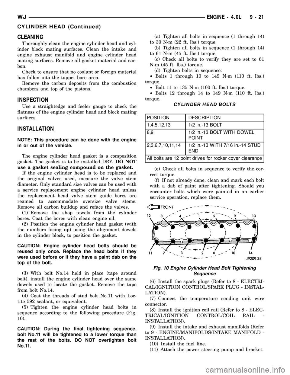
(5) Tighten the engine cylinder head bolts in
sequence according to the following procedure (Fig.
10).
CAUTION: During the final tightening sequence,
bolt No.11 will be tightened to a lower torque than
the rest of the bolts. DO NOT overtighten bolt
No.11.(a) Tighten all bolts in sequence (1 through 14)
to 30 N´m (22 ft. lbs.) torque.
(b) Tighten all bolts in sequence (1 through 14)
to 61 N´m (45 ft. lbs.) torque.
(c) Check all bolts to verify they are set to 61
N´m (45 ft. lbs.) torque.
(d) Tighten bolts in sequence:
²Bolts 1 through 10 to 149 N´m (110 ft. lbs.)
torque.
²Bolt 11 to 135 N´m (100 ft. lbs.) torque.
²Bolts 12 through 14 to 149 N´m (110 ft. lbs.)
torque.
CYLINDER HEAD BOLTS
POSITION DESCRIPTION
1,4,5,12,13 1/2 in.-13 BOLT
8,9 1/2 in.-13 BOLT WITH DOWEL
POINT
2,3,6,7,10,11,14 1/2 in.-13 WITH 7/16 in.-14 STUD
END
All bolts are 12 point drives for rocker cover clearance
(e) Check all bolts in sequence to verify the cor-
rect torque.
(f) If not already done, clean and mark each bolt
with a dab of paint after tightening. Should you
encounter bolts which were painted in an earlier
service operation, replace them.
(6) Install the spark plugs (Refer to 8 - ELECTRI-
CAL/IGNITION CONTROL/SPARK PLUG - INSTAL-
LATION).
(7) Connect the temperature sending unit wire
connector.
(8) Install the ignition coil rail (Refer to 8 - ELEC-
TRICAL/IGNITION CONTROL/COIL RAIL -
INSTALLATION).
(9) Install the intake and exhaust manifolds (Refer
to 9 - ENGINE/MANIFOLDS/INTAKE MANIFOLD -
INSTALLATION).
(10) Install the fuel line.
(11) Attach the power steering pump and bracket.
Fig. 10 Engine Cylinder Head Bolt Tightening
Sequence
WJENGINE - 4.0L 9 - 21
CYLINDER HEAD (Continued)