2003 JEEP GRAND CHEROKEE oil cooler
[x] Cancel search: oil coolerPage 1534 of 2199
TEST CONDITION INDICATION
Governor pressure low at
all mph figuresFaulty governor pressure
solenoid, transmission
control module, or
governor pressure
sensor
Lubrication pressure low
at all throttle positionsClogged fluid cooler or
lines, seal rings leaking,
worn pump bushings,
pump, clutch retainer, or
clogged filter.
Line pressure high Output shaft plugged,
sticky regulator valve
Line pressure low Sticky regulator valve,
clogged filter, worn pump
DIAGNOSIS AND TESTING - AIR CHECKING
TRANSMISSION CLUTCH AND BAND
OPERATION
Air-pressure testing can be used to check transmis-
sion front/rear clutch and band operation. The test
can be conducted with the transmission either in the
vehicle or on the work bench, as a final check, after
overhaul.
Air-pressure testing requires that the oil pan and
valve body be removed from the transmission. The
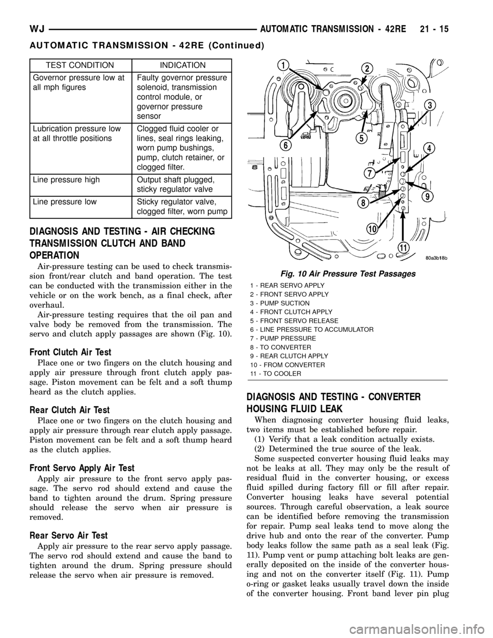
servo and clutch apply passages are shown (Fig. 10).
Front Clutch Air Test
Place one or two fingers on the clutch housing and
apply air pressure through front clutch apply pas-
sage. Piston movement can be felt and a soft thump
heard as the clutch applies.
Rear Clutch Air Test
Place one or two fingers on the clutch housing and
apply air pressure through rear clutch apply passage.
Piston movement can be felt and a soft thump heard
as the clutch applies.
Front Servo Apply Air Test
Apply air pressure to the front servo apply pas-
sage. The servo rod should extend and cause the
band to tighten around the drum. Spring pressure
should release the servo when air pressure is
removed.
Rear Servo Air Test
Apply air pressure to the rear servo apply passage.
The servo rod should extend and cause the band to
tighten around the drum. Spring pressure should
release the servo when air pressure is removed.
DIAGNOSIS AND TESTING - CONVERTER
HOUSING FLUID LEAK
When diagnosing converter housing fluid leaks,
two items must be established before repair.
(1) Verify that a leak condition actually exists.
(2) Determined the true source of the leak.
Some suspected converter housing fluid leaks may
not be leaks at all. They may only be the result of
residual fluid in the converter housing, or excess
fluid spilled during factory fill or fill after repair.
Converter housing leaks have several potential
sources. Through careful observation, a leak source
can be identified before removing the transmission
for repair. Pump seal leaks tend to move along the
drive hub and onto the rear of the converter. Pump
body leaks follow the same path as a seal leak (Fig.
11). Pump vent or pump attaching bolt leaks are gen-
erally deposited on the inside of the converter hous-
ing and not on the converter itself (Fig. 11). Pump
o-ring or gasket leaks usually travel down the inside
of the converter housing. Front band lever pin plug
Fig. 10 Air Pressure Test Passages
1 - REAR SERVO APPLY
2 - FRONT SERVO APPLY
3 - PUMP SUCTION
4 - FRONT CLUTCH APPLY
5 - FRONT SERVO RELEASE
6 - LINE PRESSURE TO ACCUMULATOR
7 - PUMP PRESSURE
8 - TO CONVERTER
9 - REAR CLUTCH APPLY
10 - FROM CONVERTER
11 - TO COOLER
WJAUTOMATIC TRANSMISSION - 42RE 21 - 15
AUTOMATIC TRANSMISSION - 42RE (Continued)
Page 1536 of 2199
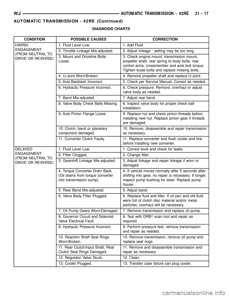
DIAGNOSIS CHARTS
CONDITION POSSIBLE CAUSES CORRECTION
HARSH
ENGAGEMENT
(FROM NEUTRAL TO
DRIVE OR REVERSE)1. Fluid Level Low. 1. Add Fluid
2. Throttle Linkage Mis-adjusted. 2. Adjust linkage - setting may be too long.
3. Mount and Driveline Bolts
Loose.3. Check engine mount, transmission mount,
propeller shaft, rear spring to body bolts, rear
control arms, crossmember and axle bolt torque.
Tighten loose bolts and replace missing bolts.
4. U-Joint Worn/Broken. 4. Remove propeller shaft and replace U-Joint.
5. Axle Backlash Incorrect. 5. Check per Service Manual. Correct as needed.
6. Hydraulic Pressure Incorrect. 6. Check pressure. Remove, overhaul or adjust
valve body as needed.
7. Band Mis-adjusted. 7. Adjust rear band.
8. Valve Body Check Balls Missing. 8. Inspect valve body for proper check ball
installation.
9. Axle Pinion Flange Loose. 9. Replace nut and check pinion threads before
installing new nut. Replace pinion gear if threads
are damaged.
10. Clutch, band or planetary
component damaged.10. Remove, disassemble and repair transmission
as necessary.
11. Converter Clutch Faulty. 11. Replace converter and flush cooler and line
before installing new converter.
DELAYED
ENGAGEMENT
(FROM NEUTRAL TO
DRIVE OR REVERSE)1. Fluid Level Low. 1. Correct level and check for leaks.
2. Filter Clogged. 2. Change filter.
3. Gearshift Linkage Mis-adjusted. 3. Adjust linkage and repair linkage if worn or
damaged.
4. Torque Converter Drain Back
(Oil drains from torque converter
into transmission sump).4. If vehicle moves normally after 5 seconds after
shifting into gear, no repair is necessary. If longer,
inspect pump bushing for wear. Replace pump
house.
5. Rear Band Mis-adjusted. 5. Adjust band.
6. Valve Body Filter Plugged. 6. Replace fluid and filter. If oil pan and old fluid
were full of clutch disc material and/or metal
particles, overhaul will be necessary.
7. Oil Pump Gears Worn/Damaged. 7. Remove transmission and replace oil pump.
8. Governor Circuit and Solenoid
Valve Electrical Fault.8. Test with DRBTscan tool and repair as
required.
9. Hydraulic Pressure Incorrect. 9. Perform pressure test, remove transmission
and repair as needed.
10. Reaction Shaft Seal Rings
Worn/Broken.10. Remove transmission, remove oil pump and
replace seal rings.
11. Rear Clutch/Input Shaft, Rear
Clutch Seal Rings Damaged.11. Remove and disassemble transmission and
repair as necessary.
12. Regulator Valve Stuck. 12. Clean.
13. Cooler Plugged. 13. Transfer case failure can plug cooler.
WJAUTOMATIC TRANSMISSION - 42RE 21 - 17
AUTOMATIC TRANSMISSION - 42RE (Continued)
Page 1537 of 2199
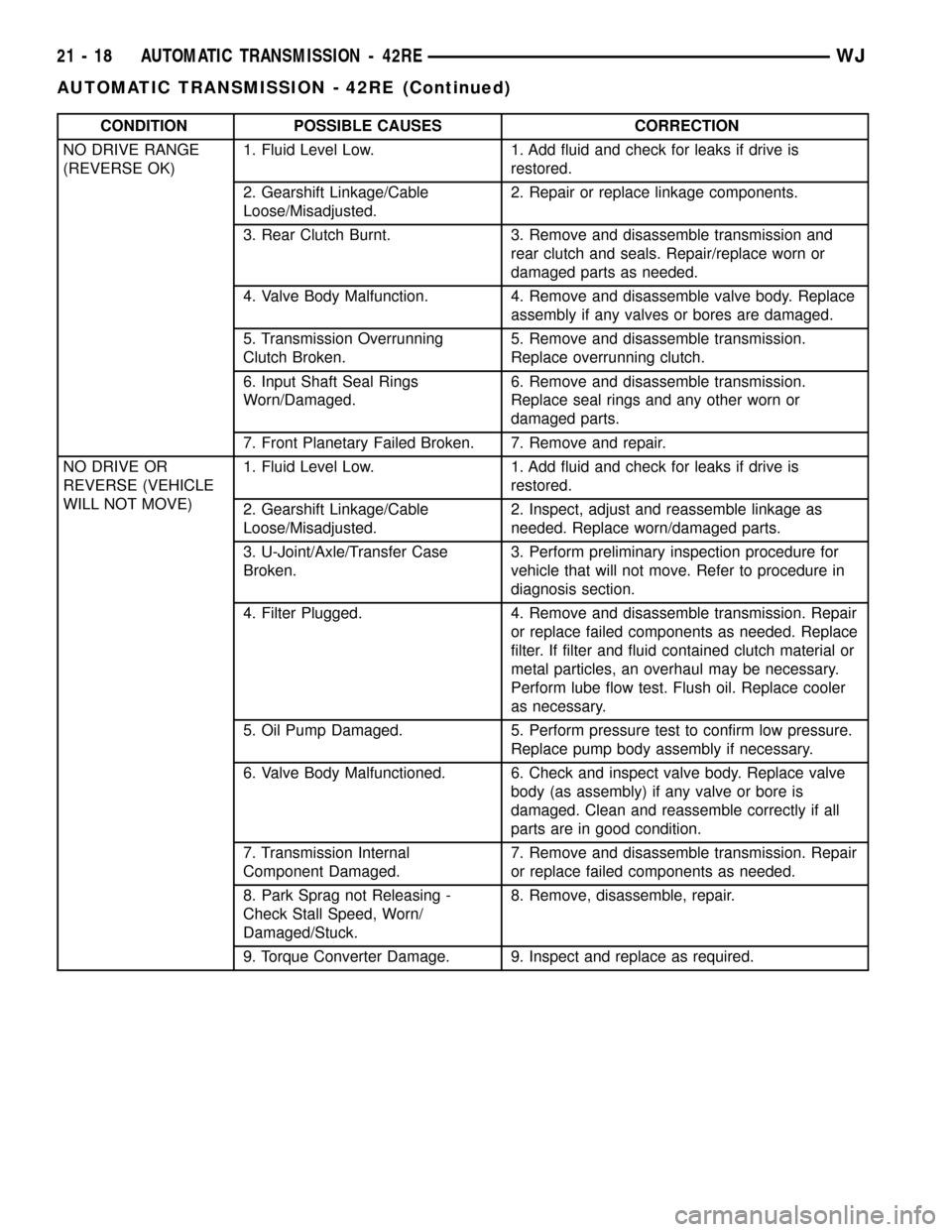
CONDITION POSSIBLE CAUSES CORRECTION
NO DRIVE RANGE
(REVERSE OK)1. Fluid Level Low. 1. Add fluid and check for leaks if drive is
restored.
2. Gearshift Linkage/Cable
Loose/Misadjusted.2. Repair or replace linkage components.
3. Rear Clutch Burnt. 3. Remove and disassemble transmission and
rear clutch and seals. Repair/replace worn or
damaged parts as needed.
4. Valve Body Malfunction. 4. Remove and disassemble valve body. Replace
assembly if any valves or bores are damaged.
5. Transmission Overrunning
Clutch Broken.5. Remove and disassemble transmission.
Replace overrunning clutch.
6. Input Shaft Seal Rings
Worn/Damaged.6. Remove and disassemble transmission.
Replace seal rings and any other worn or
damaged parts.
7. Front Planetary Failed Broken. 7. Remove and repair.
NO DRIVE OR
REVERSE (VEHICLE
WILL NOT MOVE)1. Fluid Level Low. 1. Add fluid and check for leaks if drive is
restored.
2. Gearshift Linkage/Cable
Loose/Misadjusted.2. Inspect, adjust and reassemble linkage as
needed. Replace worn/damaged parts.
3. U-Joint/Axle/Transfer Case
Broken.3. Perform preliminary inspection procedure for
vehicle that will not move. Refer to procedure in
diagnosis section.
4. Filter Plugged. 4. Remove and disassemble transmission. Repair
or replace failed components as needed. Replace
filter. If filter and fluid contained clutch material or
metal particles, an overhaul may be necessary.
Perform lube flow test. Flush oil. Replace cooler
as necessary.
5. Oil Pump Damaged. 5. Perform pressure test to confirm low pressure.
Replace pump body assembly if necessary.
6. Valve Body Malfunctioned. 6. Check and inspect valve body. Replace valve
body (as assembly) if any valve or bore is
damaged. Clean and reassemble correctly if all
parts are in good condition.
7. Transmission Internal
Component Damaged.7. Remove and disassemble transmission. Repair
or replace failed components as needed.
8. Park Sprag not Releasing -
Check Stall Speed, Worn/
Damaged/Stuck.8. Remove, disassemble, repair.
9. Torque Converter Damage. 9. Inspect and replace as required.
21 - 18 AUTOMATIC TRANSMISSION - 42REWJ
AUTOMATIC TRANSMISSION - 42RE (Continued)
Page 1540 of 2199
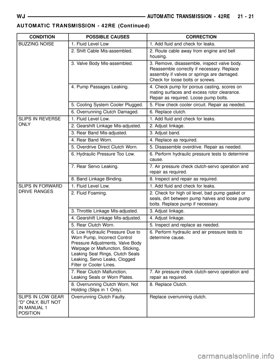
CONDITION POSSIBLE CAUSES CORRECTION
BUZZING NOISE 1. Fluid Level Low 1. Add fluid and check for leaks.
2. Shift Cable Mis-assembled. 2. Route cable away from engine and bell
housing.
3. Valve Body Mis-assembled. 3. Remove, disassemble, inspect valve body.
Reassemble correctly if necessary. Replace
assembly if valves or springs are damaged.
Check for loose bolts or screws.
4. Pump Passages Leaking. 4. Check pump for porous casting, scores on
mating surfaces and excess rotor clearance.
Repair as required. Loose pump bolts.
5. Cooling System Cooler Plugged. 5. Flow check cooler circuit. Repair as needed.
6. Overrunning Clutch Damaged. 6. Replace clutch.
SLIPS IN REVERSE
ONLY1. Fluid Level Low. 1. Add fluid and check for leaks.
2. Gearshift Linkage Mis-adjusted. 2. Adjust linkage.
3. Rear Band Mis-adjusted. 3. Adjust band.
4. Rear Band Worn. 4. Replace as required.
5. Overdrive Direct Clutch Worn. 5. Disassemble overdrive. Repair as needed.
6. Hydraulic Pressure Too Low. 6. Perform hydraulic pressure tests to determine
cause.
7. Rear Servo Leaking. 7. Air pressure check clutch-servo operation and
repair as required.
8. Band Linkage Binding. 8. Inspect and repair as required.
SLIPS IN FORWARD
DRIVE RANGES1. Fluid Level Low. 1. Add fluid and check for leaks.
2. Fluid Foaming. 2. Check for high oil level, bad pump gasket or
seals, dirt between pump halves and loose pump
bolts. Replace pump if necessary.
3. Throttle Linkage Mis-adjusted. 3. Adjust linkage.
4. Gearshift Linkage Mis-adjusted. 4. Adjust linkage.
5. Rear Clutch Worn. 5. Inspect and replace as needed.
6. Low Hydraulic Pressure Due to
Worn Pump, Incorrect Control
Pressure Adjustments, Valve Body
Warpage or Malfunction, Sticking,
Leaking Seal Rings, Clutch Seals
Leaking, Servo Leaks, Clogged
Filter or Cooler Lines.6. Perform hydraulic and air pressure tests to
determine cause.
7. Rear Clutch Malfunction,
Leaking Seals or Worn Plates.7. Air pressure check clutch-servo operation and
repair as required.
8. Overrunning Clutch Worn, Not
Holding (Slips in 1 Only).8. Replace Clutch.
SLIPS IN LOW GEAR
9D9ONLY, BUT NOT
IN MANUAL 1
POSITIONOverrunning Clutch Faulty. Replace overrunning clutch.
WJAUTOMATIC TRANSMISSION - 42RE 21 - 21
AUTOMATIC TRANSMISSION - 42RE (Continued)
Page 1541 of 2199
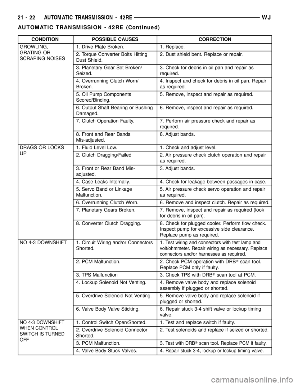
CONDITION POSSIBLE CAUSES CORRECTION
GROWLING,
GRATING OR
SCRAPING NOISES1. Drive Plate Broken. 1. Replace.
2. Torque Converter Bolts Hitting
Dust Shield.2. Dust shield bent. Replace or repair.
3. Planetary Gear Set Broken/
Seized.3. Check for debris in oil pan and repair as
required.
4. Overrunning Clutch Worn/
Broken.4. Inspect and check for debris in oil pan. Repair
as required.
5. Oil Pump Components
Scored/Binding.5. Remove, inspect and repair as required.
6. Output Shaft Bearing or Bushing
Damaged.6. Remove, inspect and repair as required.
7. Clutch Operation Faulty. 7. Perform air pressure check and repair as
required.
8. Front and Rear Bands
Mis-adjusted.8. Adjust bands.
DRAGS OR LOCKS
UP1. Fluid Level Low. 1. Check and adjust level.
2. Clutch Dragging/Failed 2. Air pressure check clutch operation and repair
as required.
3. Front or Rear Band Mis-
adjusted.3. Adjust bands.
4. Case Leaks Internally. 4. Check for leakage between passages in case.
5. Servo Band or Linkage
Malfunction.5. Air pressure check servo operation and repair
as required.
6. Overrunning Clutch Worn. 6. Remove and inspect clutch. Repair as required.
7. Planetary Gears Broken. 7. Remove, inspect and repair as required (look
for debris in oil pan).
8. Converter Clutch Dragging. 8. Check for plugged cooler. Perform flow check.
Inspect pump for excessive side clearance.
Replace pump as required.
NO 4-3 DOWNSHIFT 1. Circuit Wiring and/or Connectors
Shorted.1.
Test wiring and connectors with test lamp and
volt/ohmmeter. Repair wiring as necessary. Replace
connectors and/or harnesses as required.
2. PCM Malfunction. 2. Check PCM operation with DRBTscan tool.
Replace PCM only if faulty.
3. TPS Malfunction 3. Check TPS with DRBTscan tool at PCM.
4. Lockup Solenoid Not Venting. 4. Remove valve body and replace solenoid
assembly if plugged or shorted.
5. Overdrive Solenoid Not Venting. 5. Remove valve body and replace solenoid if
plugged or shorted.
6. Valve Body Valve Sticking. 6. Repair stuck 3-4 shift valve or lockup timing
valve.
NO 4-3 DOWNSHIFT
WHEN CONTROL
SWITCH IS TURNED
OFF1. Control Switch Open/Shorted. 1. Test and replace switch if faulty.
2. Overdrive Solenoid Connector
Shorted.2. Test solenoids and replace if seized or shorted.
3. PCM Malfunction. 3.
Test with DRBTscan tool. Replace PCM if faulty.
4. Valve Body Stuck Valves. 4.Repair stuck 3-4, lockup or lockup timing valve.
21 - 22 AUTOMATIC TRANSMISSION - 42REWJ
AUTOMATIC TRANSMISSION - 42RE (Continued)
Page 1546 of 2199

REMOVAL
The overdrive unit can be removed and serviced
separately. It is not necessary to remove the entire
transmission assembly to perform overdrive unit
repairs.
If only the overdrive unit requires service, refer to
Overdrive Removal for proper procedures.
CAUTION: The transmission and torque converter
must be removed as an assembly to avoid compo-
nent damage. The converter driveplate, pump bush-
ing, or oil seal can be damaged if the converter is
left attached to the driveplate during removal. Be
sure to remove the transmission and converter as
an assembly.
(1) Disconnect battery negative cable.
(2) Disconnect and lower or remove necessary
exhaust components.
(3) Disconnect fluid cooler lines at transmission.
(4) Remove starter motor. (Refer to 8 - ELECTRI-
CAL/STARTING/STARTER MOTOR - REMOVAL)
(5) Disconnect and remove crankshaft position sen-
sor. (Refer to 14 - FUEL SYSTEM/FUEL INJEC-
TION/CRANKSHAFT POSITION SENSOR -
REMOVAL) Retain sensor attaching bolts.
CAUTION: The crankshaft position sensor will be
damaged if the transmission is removed, or
installed, while the sensor is still bolted to the
engine block, or transmission (4.0L only). To avoid
damage, be sure to remove the sensor before
removing the transmission.
(6) Remove the bolts holding the bell housing
brace to the transmission.
(7) Remove nut holding the bell housing brace to
the engine to transmission bending brace.
(8) Remove the bell housing brace from the trans-
mission (Fig. 13).
(9) Remove the bolt holding the torque converter
cover to the transmission.
(10) Remove the torque converter cover from the
transmission.
(11) If transmission is being removed for overhaul,
remove transmission oil pan, drain fluid and reinstall
pan.
(12) Remove fill tube bracket bolts and pull tube
out of transmission. Retain fill tube seal. On4x4
models, it will also be necessary to remove bolt
attaching transfer case vent tube to converter hous-
ing.
(13) Rotate crankshaft in clockwise direction until
converter bolts are accessible. Then remove bolts one
at a time. Rotate crankshaft with socket wrench on
dampener bolt.(14) Mark propeller shaft and axle yokes for
assembly alignment. Then disconnect and remove
propeller shaft. On4x4models, remove both propel-
ler shafts.
(15) Disconnect wires from park/neutral position
switch and transmission solenoid.
(16) Disconnect gearshift cable from transmission
manual valve lever (Fig. 14).
Fig. 13 Bell Housing Brace and Converter Cover
1 - Transmission
2 - Torque Converter Cover
3 - Bellhousing Brace
Fig. 14 Transmission Shift Cable
1 - SHIFT CABLE
2 - MANUAL LEVER
3 - MANUAL LEVER
WJAUTOMATIC TRANSMISSION - 42RE 21 - 27
AUTOMATIC TRANSMISSION - 42RE (Continued)
Page 1575 of 2199
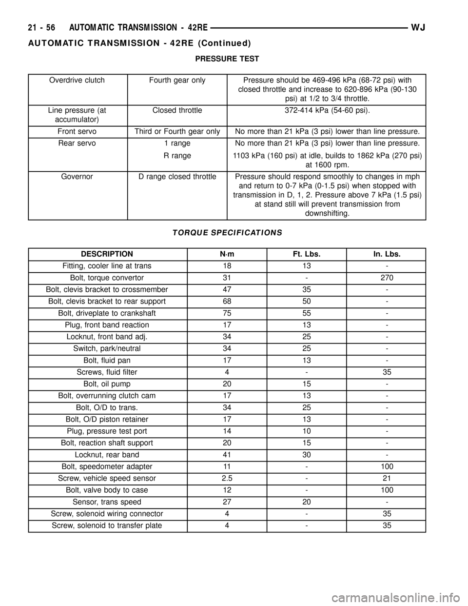
PRESSURE TEST
Overdrive clutch Fourth gear only Pressure should be 469-496 kPa (68-72 psi) with
closed throttle and increase to 620-896 kPa (90-130
psi) at 1/2 to 3/4 throttle.
Line pressure (at
accumulator)Closed throttle 372-414 kPa (54-60 psi).
Front servo Third or Fourth gear only No more than 21 kPa (3 psi) lower than line pressure.
Rear servo 1 range No more than 21 kPa (3 psi) lower than line pressure.
R range 1103 kPa (160 psi) at idle, builds to 1862 kPa (270 psi)
at 1600 rpm.
Governor D range closed throttle Pressure should respond smoothly to changes in mph
and return to 0-7 kPa (0-1.5 psi) when stopped with
transmission in D, 1, 2. Pressure above 7 kPa (1.5 psi)
at stand still will prevent transmission from
downshifting.
TORQUE SPECIFICATIONS
DESCRIPTION N´m Ft. Lbs. In. Lbs.
Fitting, cooler line at trans 18 13 -
Bolt, torque convertor 31 - 270
Bolt, clevis bracket to crossmember 47 35 -
Bolt, clevis bracket to rear support 68 50 -
Bolt, driveplate to crankshaft 75 55 -
Plug, front band reaction 17 13 -
Locknut, front band adj. 34 25 -
Switch, park/neutral 34 25 -
Bolt, fluid pan 17 13 -
Screws, fluid filter 4 - 35
Bolt, oil pump 20 15 -
Bolt, overrunning clutch cam 17 13 -
Bolt, O/D to trans. 34 25 -
Bolt, O/D piston retainer 17 13 -
Plug, pressure test port 14 10 -
Bolt, reaction shaft support 20 15 -
Locknut, rear band 41 30 -
Bolt, speedometer adapter 11 - 100
Screw, vehicle speed sensor 2.5 - 21
Bolt, valve body to case 12 - 100
Sensor, trans speed 27 20 -
Screw, solenoid wiring connector 4 - 35
Screw, solenoid to transfer plate 4 - 35
21 - 56 AUTOMATIC TRANSMISSION - 42REWJ
AUTOMATIC TRANSMISSION - 42RE (Continued)
Page 1578 of 2199

Remover, Bushing - SP-5324
Installer, Bushing - SP-5325
Compressor, Spring - C-3575-A
Gauge - 6312
Adapter, Band Adjuster - C-3705
Flusher, Oil Cooler - 6906-B
Installer, Piston - 8114
Remover, Bushing - 6957
Installer, Bushing - 6951
Retainer, Detent Ball and Spring - 6583
WJAUTOMATIC TRANSMISSION - 42RE 21 - 59
AUTOMATIC TRANSMISSION - 42RE (Continued)