2003 JEEP GRAND CHEROKEE Brake light ground
[x] Cancel search: Brake light groundPage 1169 of 2199

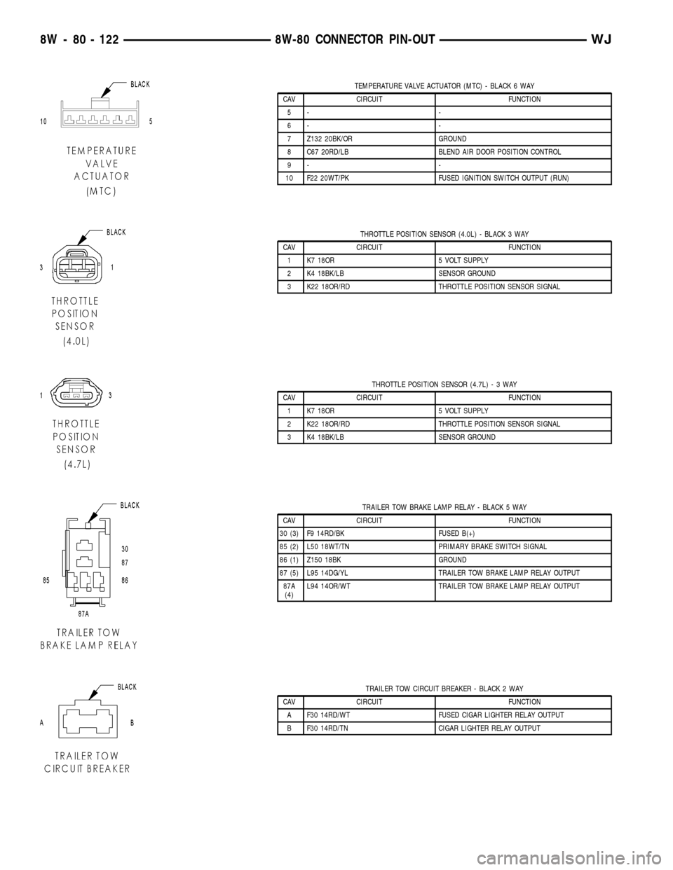
TEMPERATURE VALVE ACTUATOR (MTC) - BLACK 6 WAY
CAV CIRCUIT FUNCTION
5- -
6- -
7 Z132 20BK/OR GROUND
8 C67 20RD/LB BLEND AIR DOOR POSITION CONTROL
9- -
10 F22 20WT/PK FUSED IGNITION SWITCH OUTPUT (RUN)
THROTTLE POSITION SENSOR (4.0L) - BLACK 3 WAY
CAV CIRCUIT FUNCTION
1 K7 18OR 5 VOLT SUPPLY
2 K4 18BK/LB SENSOR GROUND
3 K22 18OR/RD THROTTLE POSITION SENSOR SIGNAL
THROTTLE POSITION SENSOR (4.7L)-3WAY
CAV CIRCUIT FUNCTION
1 K7 18OR 5 VOLT SUPPLY
2 K22 18OR/RD THROTTLE POSITION SENSOR SIGNAL
3 K4 18BK/LB SENSOR GROUND
TRAILER TOW BRAKE LAMP RELAY - BLACK 5 WAY
CAV CIRCUIT FUNCTION
30 (3) F9 14RD/BK FUSED B(+)
85 (2) L50 18WT/TN PRIMARY BRAKE SWITCH SIGNAL
86 (1) Z150 18BK GROUND
87 (5) L95 14DG/YL TRAILER TOW BRAKE LAMP RELAY OUTPUT
87A
(4)L94 14OR/WT TRAILER TOW BRAKE LAMP RELAY OUTPUT
TRAILER TOW CIRCUIT BREAKER - BLACK 2 WAY
CAV CIRCUIT FUNCTION
A F30 14RD/WT FUSED CIGAR LIGHTER RELAY OUTPUT
B F30 14RD/TN CIGAR LIGHTER RELAY OUTPUT
8W - 80 - 122 8W-80 CONNECTOR PIN-OUTWJ
Page 1170 of 2199

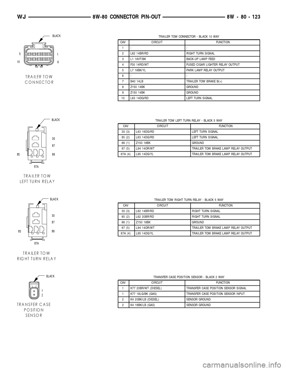
TRAILER TOW CONNECTOR - BLACK 10 WAY
CAV CIRCUIT FUNCTION
1- -
2 L62 14BR/RD RIGHT TURN SIGNAL
3 L1 18VT/BK BACK-UP LAMP FEED
4 F30 14RD/WT FUSED CIGAR LIGHTER RELAY OUTPUT
5 L7 18BK/YL PARK LAMP RELAY OUTPUT
6- -
7 B40 14LB TRAILER TOW BRAKE B(+)
8 Z150 14BK GROUND
9 Z150 14BK GROUND
10 L63 14DG/RD LEFT TURN SIGNAL
TRAILER TOW LEFT TURN RELAY - BLACK 5 WAY
CAV CIRCUIT FUNCTION
30 (3) L63 16DG/RD LEFT TURN SIGNAL
85 (2) L63 14DG/RD LEFT TURN SIGNAL
86 (1) Z150 18BK GROUND
87 (5) L94 14OR/WT TRAILER TOW BRAKE LAMP RELAY OUTPUT
87A (4) L95 14DG/YL TRAILER TOW BRAKE LAMP RELAY OUTPUT
TRAILER TOW RIGHT TURN RELAY - BLACK 5 WAY
CAV CIRCUIT FUNCTION
30 (3) L62 14BR/RD RIGHT TURN SIGNAL
85 (2) L62 20BR/RD RIGHT TURN SIGNAL
86 (1) Z150 18BK GROUND
87 (5) L94 14OR/WT TRAILER TOW BRAKE LAMP RELAY OUTPUT
87A (4) L95 14DG/YL TRAILER TOW BRAKE LAMP RELAY OUTPUT
TRANSFER CASE POSITION SENSOR - BLACK 2 WAY
CAV CIRCUIT FUNCTION
1 K77 20BR/WT (DIESEL) TRANSFER CASE POSITION SENSOR SIGNAL
1 K77 18LG/BK (GAS) TRANSFER CASE POSITION SENSOR INPUT
2 K4 20BK/LB (DIESEL) SENSOR GROUND
2 K4 18BK/LB (GAS) SENSOR GROUND
WJ8W-80 CONNECTOR PIN-OUT 8W - 80 - 123
Page 1176 of 2199

8W-91 CONNECTOR/GROUND/SPLICE LOCATION
TABLE OF CONTENTS
page
CONNECTOR/GROUND/SPLICE LOCATION
DESCRIPTION..........................1
CONNECTOR/GROUND/SPLICE
LOCATION
DESCRIPTION
This section provides illustrations identifying con-
nector, ground, and splice locations in the vehicle.Connector, ground, and splice indexes are provided.
Use the wiring diagrams in each section for connec-
tor, ground, and splice identification. Refer to the
appropriate index for the proper figure number. For
items that are not shown in this section N/S is placed
in the Fig. column.
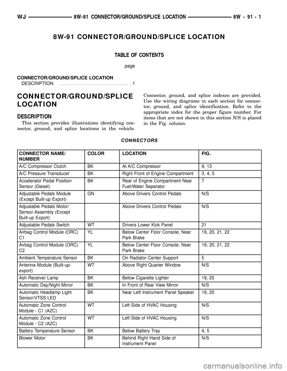
CONNECTORS
CONNECTOR NAME/
NUMBERCOLOR LOCATION FIG.
A/C Compressor Clutch BK At A/C Compressor 9, 13
A/C Pressure Transducer BK Right Front of Engine Compartment 3, 4, 5
Accelerator Pedal Position
Sensor (Diesel)BK Rear of Engine Compartment Near
Fuel/Water Seperator7
Adjustable Pedals Module
(Except Built-up Export)GN Above Drivers Control Pedals N/S
Adjustable Pedals Motor/
Sensor Assembly (Except
Built-up Export)Above Drivers Control Pedals N/S
Adjustable Pedals Switch WT Drivers Lower Kick Panel 21
Airbag Control Module (ORC)
C1YL Below Center Floor Console, Near
Park Brake19, 20, 21, 22
Airbag Control Module (ORC)
C2YL Below Center Floor Console, Near
Park Brake19, 20, 21, 22
Ambient Temperature Sensor BK On Radiator Center Support 5
Antenna Module (Built-up-
export)WT Above Right Quarter Window N/S
Ash Receiver Lamp BK Below Cigarette Lighter 19, 20
Automatic Day/Night Mirror BK In Front of Rear View Mirror N/S
Automatic Headlamp Light
Sensor/VTSS LEDBK Near Left Instrument Panel Speaker 19, 20
Automatic Zone Control
Module - C1 (AZC)WT Left Side of HVAC Housing N/S
Automatic Zone Control
Module - C2 (AZC)WT Left Side of HVAC Housing N/S
Battery Temperature Sensor BK Below Battery Tray 4, 5
Blower Motor BK Behind Right Hand Side of
Instrument PanelN/S
WJ8W-91 CONNECTOR/GROUND/SPLICE LOCATION 8W - 91 - 1
Page 1189 of 2199

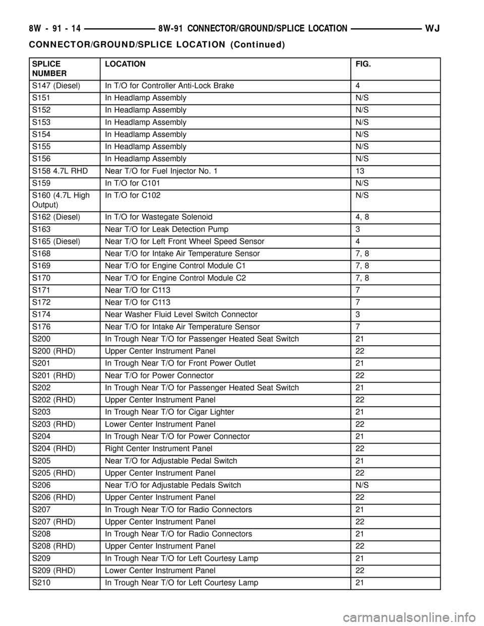
SPLICE
NUMBERLOCATION FIG.
S147 (Diesel) In T/O for Controller Anti-Lock Brake 4
S151 In Headlamp Assembly N/S
S152 In Headlamp Assembly N/S
S153 In Headlamp Assembly N/S
S154 In Headlamp Assembly N/S
S155 In Headlamp Assembly N/S
S156 In Headlamp Assembly N/S
S158 4.7L RHD Near T/O for Fuel Injector No. 1 13
S159 In T/O for C101 N/S
S160 (4.7L High
Output)In T/O for C102 N/S
S162 (Diesel) In T/O for Wastegate Solenoid 4, 8
S163 Near T/O for Leak Detection Pump 3
S165 (Diesel) Near T/O for Left Front Wheel Speed Sensor 4
S168 Near T/O for Intake Air Temperature Sensor 7, 8
S169 Near T/O for Engine Control Module C1 7, 8
S170 Near T/O for Engine Control Module C2 7, 8
S171 Near T/O for C113 7
S172 Near T/O for C113 7
S174 Near Washer Fluid Level Switch Connector 3
S176 Near T/O for Intake Air Temperature Sensor 7
S200 In Trough Near T/O for Passenger Heated Seat Switch 21
S200 (RHD) Upper Center Instrument Panel 22
S201 In Trough Near T/O for Front Power Outlet 21
S201 (RHD) Near T/O for Power Connector 22
S202 In Trough Near T/O for Passenger Heated Seat Switch 21
S202 (RHD) Upper Center Instrument Panel 22
S203 In Trough Near T/O for Cigar Lighter 21
S203 (RHD) Lower Center Instrument Panel 22
S204 In Trough Near T/O for Power Connector 21
S204 (RHD) Right Center Instrument Panel 22
S205 Near T/O for Adjustable Pedal Switch 21
S205 (RHD) Upper Center Instrument Panel 22
S206 Near T/O for Adjustable Pedals Switch N/S
S206 (RHD) Upper Center Instrument Panel 22
S207 In Trough Near T/O for Radio Connectors 21
S207 (RHD) Upper Center Instrument Panel 22
S208 In Trough Near T/O for Radio Connectors 21
S208 (RHD) Upper Center Instrument Panel 22
S209 In Trough Near T/O for Left Courtesy Lamp 21
S209 (RHD) Lower Center Instrument Panel 22
S210 In Trough Near T/O for Left Courtesy Lamp 21
8W - 91 - 14 8W-91 CONNECTOR/GROUND/SPLICE LOCATIONWJ
CONNECTOR/GROUND/SPLICE LOCATION (Continued)
Page 1381 of 2199

(7) Connect throttle cable and speed control cable
to throttle body.
(8) Install fuel rail (Refer to 14 - FUEL SYSTEM/
FUEL DELIVERY/FUEL RAIL - INSTALLATION).
(9) Install ignition coil towers (Refer to 8 - ELEC-
TRICAL/IGNITION CONTROL/IGNITION COIL -
INSTALLATION).
(10) Install coolant temperature sensor (Refer to 7
- COOLING/ENGINE/ENGINE COOLANT TEMP
SENSOR - INSTALLATION).
(11) Connect electrical connectors for the following
components:
²Manifold Absolute Pressure (MAP) Sensor
²Intake Air Temperature (IAT) Sensor
²Throttle Position (TPS) Sensor
²Coolant Temperature (CTS) Sensor
²Idle Air Control (IAC) Motor
²Ignition coil towers
²Fuel injectors
(12) Install top oil dipstick tube retaining bolt and
ground strap.
(13) Install right side engine lifting stud.
(14) Install generator including electrical connec-
tions (Refer to 8 - ELECTRICAL/CHARGING/GEN-
ERATOR - INSTALLATION).
(15) Connect Vapor purge hose, Brake booster
hose, Speed control servo hose, Positive crankcase
ventilation (PCV) hose.
(16) Install air conditioning compressor including
electrical connections.
(17) Fill cooling system (Refer to 7 - COOLING -
STANDARD PROCEDURE).
(18) Install accessory drive belt (Refer to 7 -
COOLING/ACCESSORY DRIVE/DRIVE BELTS -
INSTALLATION).
(19) Install cowl to hood seal (Refer to 23 - BODY/
WEATHERSTRIP/SEALS/COWL WEATHERSTRIP -
INSTALLATION).
(20) Install air cleaner housing and throttle body
resonator. Tighten resonator bolts 4.5 N´m (40 in.
lbs.).
(21) Connect negative cable to battery.
EXHAUST MANIFOLD - LEFT
DESCRIPTION
The exhaust manifolds are log style with a pat-
ented flow enhancing design to maximize perfor-
mance. The exhaust manifolds are made of high
silicon molybdenum cast iron. A perforated core
graphite exhaust manifold gasket is used to improve
sealing to the cylinder head. The exhaust manifolds
are covered by a three layer laminated heat shield
for thermal protection and noise reduction. The heat
shields are fastened with a torque prevailing nutthat is backed off slightly to allow for the thermal
expansion of the exhaust manifold.
REMOVAL
(1) Disconnect negative cable for battery.
(2) Hoist vehicle.
(3) Disconnect exhaust pipe at manifold.
(4) Lower vehicle.
(5) Remove air cleaner housing and tube.
(6) Remove the front two exhaust heat shield
retaining fasteners. Raise vehicle and remove the
fasteners at rear of heat shield.
(7) Remove heat shield (Fig. 107).
(8) Lower vehicle and remove the upper exhaust
manifold retaining bolts (Fig. 107).
(9) Raise vehicle and remove the lower exhaust
manifold retaining bolts (Fig. 107).
(10) Remove exhaust manifold and gasket (Fig.
107). Manifold is removed from below the engine
compartment.
CLEANING
(1) Clean the exhaust manifold using a suitable
cleaning solvent, then allow to air dry.
(2) Clean all gasket residue from the manifold
mating surface.
INSPECTION
(1) Inspect the exhaust manifold for cracks in the
mating surface and at every mounting bolt hole.
(2) Using a straight edge and a feeler gauge, check
the mating surface for warp and twist.
(3) Inspect the manifold to exhaust pipe mating
surface for cracks, gouges, or other damage that
would prevent sealing.
INSTALLATION
(1) Install exhaust manifold and gasket from below
engine compartment.
(2) Install lower exhaust manifold fasteners (Fig.
107). DO NOT tighten until all fasteners are in
place.
(3) Lower vehicle and install upper exhaust mani-
fold fasteners (Fig. 107). Tighten all manifold bolts
starting at center and working outward to 25 N´m
(18 ft. lbs.).
CAUTION: Over tightening heat shield fasteners,
may cause shield to distort and/or crack.
(4) Install exhaust manifold heat shield (Fig. 107).
Tighten fasteners to 8 N´m (72 in. lbs.), then loosen
45 degrees.
(5) Install air cleaner housing and tube.
(6) Connect exhaust pipe to manifold.
(7) Connect negative cable to battery.
9 - 138 ENGINE - 4.7LWJ
INTAKE MANIFOLD (Continued)