2003 JEEP GRAND CHEROKEE Airbags
[x] Cancel search: AirbagsPage 579 of 2199

INSTALLATION
The following procedure is for replacement of a
faulty or damaged side curtain airbag. If the airbag
is faulty or damaged, but not deployed, review the
recommended procedures for handling non-deployed
supplemental restraints. (Refer to 8 - ELECTRICAL/
RESTRAINTS - STANDARD PROCEDURE - HAN-
DLING NON-DEPLOYED SUPPLEMENTAL
RESTRAINTS). If the side curtain airbag has been
deployed, review the recommended procedures for
service after a supplemental restraint deployment
before removing the airbag from the vehicle. (Refer to
8 - ELECTRICAL/RESTRAINTS - STANDARD PRO-
CEDURE - SERVICE AFTER A SUPPLEMENTAL
RESTRAINT DEPLOYMENT).
WARNING: ON VEHICLES EQUIPPED WITH AIR-
BAGS, DISABLE THE SUPPLEMENTAL RESTRAINT
SYSTEM BEFORE ATTEMPTING ANY STEERING
WHEEL, STEERING COLUMN, DRIVER AIRBAG,
PASSENGER AIRBAG, FRONT IMPACT SENSOR,
SIDE IMPACT SENSOR, SIDE CURTAIN AIRBAG, OR
INSTRUMENT PANEL COMPONENT DIAGNOSIS OR
SERVICE. DISCONNECT AND ISOLATE THE BAT-
TERY NEGATIVE (GROUND) CABLE, THEN WAIT
TWO MINUTES FOR THE SYSTEM CAPACITOR TO
DISCHARGE BEFORE PERFORMING FURTHER
DIAGNOSIS OR SERVICE. THIS IS THE ONLY SURE
WAY TO DISABLE THE SUPPLEMENTAL
RESTRAINT SYSTEM. FAILURE TO TAKE THE
PROPER PRECAUTIONS COULD RESULT IN ACCI-
DENTAL AIRBAG DEPLOYMENT AND POSSIBLE
PERSONAL INJURY.
WARNING: WHEN REMOVING A DEPLOYED AIR-
BAG, RUBBER GLOVES, EYE PROTECTION, AND A
LONG-SLEEVED SHIRT SHOULD BE WORN. THERE
MAY BE DEPOSITS ON THE AIRBAG UNIT AND
OTHER INTERIOR SURFACES. IN LARGE DOSES,
THESE DEPOSITS MAY CAUSE IRRITATION TO THE
SKIN AND EYES.
WARNING: USE EXTREME CARE TO PREVENT ANY
FOREIGN MATERIAL FROM ENTERING THE SIDE
CURTAIN AIRBAG, OR BECOMING ENTRAPPED
BETWEEN THE SIDE CURTAIN AIRBAG CUSHION
AND THE HEADLINER. FAILURE TO OBSERVE THIS
WARNING COULD RESULT IN OCCUPANT INJURIES
UPON AIRBAG DEPLOYMENT.
(1) Position the side curtain airbag into the vehicle
as a unit.(2) Align the push-in fastener that secures the
inflator of the side curtain airbag to the locating hole
in the roof side rail and, using hand pressure, push
firmly on the retainer until it is fully seated (Fig. 45).
(3) Align the three push-in fasteners that secure
the extruded plastic channel of the side curtain air-
bag to the locating holes in the roof side rail and,
using hand pressure, push firmly on each retainer
until it is fully seated.
(4) Install and tighten the nine screws that secure
the side curtain airbag channel and inflator mount-
ing bracket to the spring nuts in the roof side rail.
Tighten the screws to 6 N´m (50 in. lbs.).
(5) Align the side curtain airbag front tether plas-
tic retainer with the hole in the upper A-pillar and,
using hand pressure, push firmly on the retainer
until it is fully seated.
(6) Engage the side curtain airbag front tether
hook and plastic retainer clip into the slot in the
lower A-pillar.
(7) Engage the side curtain airbag rear tether
hook and plastic retainer clip into the slot in the roof
rail near the D-pillar (Fig. 44).
(8) Reconnect the body wire harness connector for
the side curtain airbag inflator to the inflator connec-
tor receptacle.
(9) Reinstall the headliner into the vehicle. (Refer
to 23 - BODY/INTERIOR/HEADLINER - INSTALLA-
TION).
(10) Do not reconnect the battery negative cable at
this time. The supplemental restraint system verifi-
cation test procedure should be performed following
service of any supplemental restraint system compo-
nent. (Refer to 8 - ELECTRICAL/RESTRAINTS -
STANDARD PROCEDURE - VERIFICATION TEST).
SIDE IMPACT SENSOR
DESCRIPTION
Two side impact sensors are used on this model
when it is equipped with the optional side curtain
airbags, one each for the left and right sides of the
vehicle (Fig. 46). These sensors are mounted
remotely from the bi-directional safing sensor that is
internal to the Airbag Control Module (ACM). The
side and front impact sensors are identical in con-
struction and calibration with the exception of the
right-hand and left-hand die cast aluminum mount-
ing brackets to which each front impact sensor is
secured with two screws. The side impact sensors are
secured with two screws to the base of the right and
left B-pillars just below the front seat belt retractors
and behind the lower B-pillar trim within the pas-
senger compartment.
8O - 42 RESTRAINTSWJ
SIDE CURTAIN AIRBAG (Continued)
Page 672 of 2199
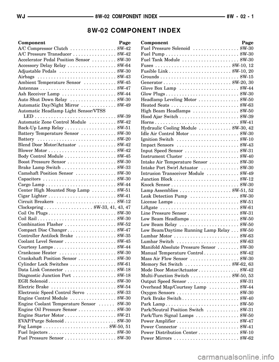
8W-02 COMPONENT INDEX
Component Page
A/C Compressor Clutch................. 8W-42
A/C Pressure Transducer................ 8W-42
Accelerator Pedal Position Sensor......... 8W-30
Accessory Delay Relay.................. 8W-64
Adjustable Pedals..................... 8W-30
Airbags............................. 8W-43
Ambient Temperature Sensor............ 8W-45
Antennas............................ 8W-47
Ash Receiver Lamp.................... 8W-44
Auto Shut Down Relay................. 8W-30
Automatic Day/Night Mirror............. 8W-49
Automatic Headlamp Light Sensor/VTSS
LED.............................. 8W-39
Automatic Zone Control Module.......... 8W-42
Back-Up Lamp Relay................... 8W-51
Battery Temperature Sensor............. 8W-30
Battery............................. 8W-20
Blend Door Motor/Actuator.............. 8W-42
Blower Motor......................... 8W-42
Body Control Module................... 8W-45
Boost Pressure Sensor.................. 8W-30
Brake Lamp Switch.................... 8W-33
Camshaft Position Sensor............... 8W-30
Capacitors........................... 8W-30
Cargo Lamp.......................... 8W-44
Center High Mounted Stop Lamp......... 8W-51
Cigar Lighter......................... 8W-41
Circuit Breakers...................... 8W-12
Clockspring.................. 8W-33, 41, 43, 47
Coil On Plugs......................... 8W-30
Coil Rail............................. 8W-30
Combination Flasher................... 8W-52
Compact Disc Changer.................. 8W-47
Controller Antilock Brake............... 8W-35
Coolant Level Sensor................... 8W-45
Courtesy Lamps....................... 8W-44
Crankcase Heater..................... 8W-30
Crankshaft Position Sensor.............. 8W-30
Cylinder Lock Switches................. 8W-61
Data Link Connector................... 8W-18
Diagnostic Junction Port................ 8W-18
EGR Solenoid......................... 8W-30
Electric Brake........................ 8W-54
Electronic Speed Control Servo........... 8W-33
Engine Control Module................. 8W-30
Engine Coolant Temperature Sensor...... 8W-30
Engine Oil Pressure Sensor.............. 8W-30
Engine Starter Motor................... 8W-21
EVAP/Purge Solenoid................... 8W-30
Fog Lamps........................ 8W-50, 51
Fuel Injectors......................... 8W-30
Fuel Pressure Sensor................... 8W-30Component Page
Fuel Pressure Solenoid................. 8W-30
Fuel Pump........................... 8W-30
Fuel Tank Module..................... 8W-30
Fuses............................ 8W-10, 12
Fusible Link....................... 8W-10, 20
Grounds............................. 8W-15
Generator......................... 8W-20, 30
Glove Box Lamp...................... 8W-44
Glow Plugs........................... 8W-30
Headlamp Leveling Motor............... 8W-50
Heated Seats......................... 8W-63
High Beam Headlamps................. 8W-50
Hood Ajar Switch...................... 8W-39
Horns............................... 8W-41
Hydraulic Cooling Module............ 8W-30, 42
Idle Air Control Motor.................. 8W-30
Ignition Switch....................... 8W-10
Impact Sensors....................... 8W-43
Input Speed Sensor.................... 8W-31
Instrument Cluster.................... 8W-40
Intake Air Temperature Sensor........... 8W-30
Intake Port Swirl Actuator.............. 8W-30
Intrusion Transceiver Module............ 8W-49
Junction Block........................ 8W-12
Knock Sensor......................... 8W-30
Lamp Assemblies................... 8W-51, 52
Leak Detection Pump.................. 8W-30
License Lamps........................ 8W-51
Liftgate............................. 8W-61
Line Pressure Sensor................... 8W-31
Low Beam Headlamps.................. 8W-50
Low Beam Relay...................... 8W-50
Low Beam/Daytime Running Lamp Relay . . . 8W-50
Lumbar Motor........................ 8W-63
Lumbar Switch....................... 8W-63
Manifold Absolute Pressure Sensor........ 8W-30
Manual Temperature Control............. 8W-42
Mass Air Flow Sensor.................. 8W-30
Memory Set Switch................. 8W-62, 63
Mode Door Motor/Actuator............... 8W-42
Multi-Function Switch............... 8W-50, 53
Output Speed Sensor................... 8W-31
Overhead Map/Courtesy Lamp........... 8W-44
Oxygen Sensors....................... 8W-30
Park Brake Switch..................... 8W-40
Park Lamp........................... 8W-50
Park/Neutral Position Switch............ 8W-31
Park/Turn Signal Lamps................ 8W-50
Power Amplifier....................... 8W-47
Power Connector...................... 8W-41
Power Distribution Center............... 8W-10
Power Mirrors........................ 8W-62
WJ8W-02 COMPONENT INDEX 8W - 02 - 1
Page 1054 of 2199

ADJUSTABLE PEDALS MOTOR/SENSOR ASSEMBLY (EXCEPT BUILT-UP-EXPORT)-6WAY
CAV CIRCUIT FUNCTION
1 Q113 20OR/DB PEDAL POSITION SENSOR FEED
2 Q112 20OR/YL PEDAL POSITION SENSOR SENSE
3 Q114 20OR/TN PEDAL POSITION SENSOR RETURN
4- -
5 Q111 16OR/GY AJDUSTABLE PEDALS MOTOR (REARWARD)
6 Q110 16OR/VT ADJUSTABLE PEDALS MOTOR (FORWARD)
ADJUSTABLE PEDALS SWITCH (EXCEPT BUILT-UP-EXPORT) - WHITE 3 WAY
CAV CIRCUIT FUNCTION
1 Y153 20BD/RD ADJUSTABLE PEDALS SWITCH FEED
2 Y152 20LG/OR ADJUSTABLE PEDALS SWITCH SENSE (REARWARD)
3 Y151 20LG/BR ADJUSTABLE PEDALS SWITCH SENSE (FORWARD)
AIRBAG CONTROL MODULE C1 (ORC C1) - YELLOW 32 WAY
CAV CIRCUIT FUNCTION
1 R72 20LB/WT (SIDE AIRBAGS) PASSENGER CURTAIN SQUIB LINE 2
2 R74 20LB/YL (SIDE AIRBAGS) PASSENGER CURTAIN SQUIB LINE 1
3- -
4- -
5- -
6- -
7- -
8- -
9 R58 20GY PASSENGER SEAT BELT SWITCH SENSE
10 R60 20VT PASSENGER SEAT BELT SWITCH GROUND
11 - -
12 - -
13 - -
14 - -
15 R132 20LG/VT (SIDE AIRBAGS) PASSENGER SIDE IMPACT SENSOR SIGNAL
16 R134 20LB/BR (SIDE AIRBAGS) PASSENGER SIDE IMPACT SENSOR GROUND
17 R131 20LG/YL (SIDE AIRBAGS) DRIVER SIDE IMPACT SENSOR SIGNAL
18 R133 20LB/DG (SIDE AIRBAGS) DRIVER SIDE IMPACT SENSOR GROUND
19 - -
20 - -
21 - -
22 - -
23 R59 20LB DRIVER SEAT BELT SWITCH GROUND
24 R57 20DG DRIVER SEAT BELT SWITCH SENSE
25 R73 20LB/BR (SIDE AIRBAGS) DRIVER CURTAIN SQUIB LINE 2
26 R75 20LB/OR (SIDE AIRBAGS) DRIVER CURTAIN SQUIB LINE 1
27 - -
28 - -
29 - -
30 - -
31 - -
32 - -
WJ8W-80 CONNECTOR PIN-OUT 8W - 80 - 7
Page 1924 of 2199
INSTRUMENT PANEL
STUCTURAL DUCT
REMOVAL
WARNING: ON VEHICLES EQUIPPED WITH AIRBAGS,
DISABLE THE AIRBAG SYSTEM BEFORE ATTEMPT-
ING ANY STEERING WHEEL, STEERING COLUMN, OR
INSTRUMENT PANEL COMPONENT DIAGNOSIS OR
SERVICE. DISCONNECT AND ISOLATE THE BATTERY
NEGATIVE (GROUND) CABLE, THEN WAIT TWO MIN-
UTES FOR THE AIRBAG SYSTEM CAPACITOR TO DIS-
CHARGE BEFORE PERFORMING FURTHER
DIAGNOSIS OR SERVICE. THIS IS THE ONLY SURE
WAY TO DISABLE THE AIRBAG SYSTEM. FAILURE TO
TAKE THE PROPER PRECAUTIONS COULD RESULT
IN ACCIDENTAL AIRBAG DEPLOYMENT AND POSSI-
BLE PERSONAL INJURY.
(1)Disconnect and isolate the battery negative cable.
(2) Remove the instrument panel from the vehicle.
(Refer to 23 - BODY/INSTRUMENT PANEL -
REMOVAL).
(3) Place the instrument panel on a suitable work
surface. Be certain to take the proper precautions to
protect the instrument panel from any possible cos-
metic damage.
(4)
Remove all of the individual components that
remain secured to the instrument panel structural duct
as described elsewhere in this service information.
INSTALLATION
WARNING: ON VEHICLES EQUIPPED WITH AIR-
BAGS, DISABLE THE AIRBAG SYSTEM BEFORE
ATTEMPTING ANY STEERING WHEEL, STEERING
COLUMN, OR INSTRUMENT PANEL COMPONENT
DIAGNOSIS OR SERVICE. DISCONNECT AND ISO-
LATE THE BATTERY NEGATIVE (GROUND) CABLE,
THEN WAIT TWO MINUTES FOR THE AIRBAG SYS-
TEM CAPACITOR TO DISCHARGE BEFORE PER-
FORMING FURTHER DIAGNOSIS OR SERVICE. THIS
IS THE ONLY SURE WAY TO DISABLE THE AIRBAG
SYSTEM. FAILURE TO TAKE THE PROPER PRE-
CAUTIONS COULD RESULT IN ACCIDENTAL AIR-
BAG DEPLOYMENT AND POSSIBLE PERSONAL
INJURY.
(1) Reinstall all of the individual components that
were removed from the instrument panel structural
duct as described elsewhere in this service informa-
tion.
(2) Reinstall the instrument panel into the vehicle.
(Refer to 23 - BODY/INSTRUMENT PANEL -
INSTALLATION).
(3) Reconnect the battery negative cable.
INSTRUMENT PANEL TOP
COVER
REMOVAL
WARNING: ON VEHICLES EQUIPPED WITH AIR-
BAGS, DISABLE THE AIRBAG SYSTEM BEFORE
ATTEMPTING ANY STEERING WHEEL, STEERING
COLUMN, OR INSTRUMENT PANEL COMPONENT
DIAGNOSIS OR SERVICE. DISCONNECT AND ISO-
LATE THE BATTERY NEGATIVE (GROUND) CABLE,
THEN WAIT TWO MINUTES FOR THE AIRBAG SYS-
TEM CAPACITOR TO DISCHARGE BEFORE PER-
FORMING FURTHER DIAGNOSIS OR SERVICE. THIS
IS THE ONLY SURE WAY TO DISABLE THE AIRBAG
SYSTEM. FAILURE TO TAKE THE PROPER PRE-
CAUTIONS COULD RESULT IN ACCIDENTAL AIR-
BAG DEPLOYMENT AND POSSIBLE PERSONAL
INJURY.
(1) Disconnect and isolate the battery negative
cable.
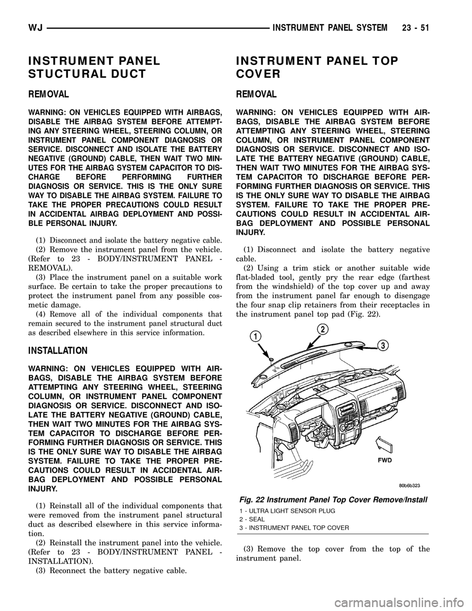
(2) Using a trim stick or another suitable wide
flat-bladed tool, gently pry the rear edge (farthest
from the windshield) of the top cover up and away
from the instrument panel far enough to disengage
the four snap clip retainers from their receptacles in
the instrument panel top pad (Fig. 22).
(3) Remove the top cover from the top of the
instrument panel.
Fig. 22 Instrument Panel Top Cover Remove/Install
1 - ULTRA LIGHT SENSOR PLUG
2 - SEAL
3 - INSTRUMENT PANEL TOP COVER
WJINSTRUMENT PANEL SYSTEM 23 - 51
Page 1929 of 2199
INSTRUMENT PANEL C-
CHANNEL COVER BRACKET
REMOVAL
WARNING: ON VEHICLES EQUIPPED WITH AIRBAGS,
DISABLE THE AIRBAG SYSTEM BEFORE ATTEMPT-
ING ANY STEERING WHEEL, STEERING COLUMN, OR
INSTRUMENT PANEL COMPONENT DIAGNOSIS OR
SERVICE. DISCONNECT AND ISOLATE THE BATTERY
NEGATIVE (GROUND) CABLE, THEN WAIT TWO MIN-
UTES FOR THE AIRBAG SYSTEM CAPACITOR TO DIS-
CHARGE BEFORE PERFORMING FURTHER
DIAGNOSIS OR SERVICE. THIS IS THE ONLY SURE
WAY TO DISABLE THE AIRBAG SYSTEM. FAILURE TO
TAKE THE PROPER PRECAUTIONS COULD RESULT
IN ACCIDENTAL AIRBAG DEPLOYMENT AND POSSI-
BLE PERSONAL INJURY.
(1)Disconnect and isolate the battery negative cable.
(2) Remove the instrument panel from the vehicle.
(Refer to 23 - BODY/INSTRUMENT PANEL -
REMOVAL).
(3) Place the instrument panel top down on a suit-
able work surface. Be certain to take the proper pre-
cautions to protect the top of the instrument panel
from any possible cosmetic damage.
(4) Disengage the radio antenna coaxial cable
retainer from the mounting hole in the instrument
panel wire harness mounting tab on the passenger
side outboard end of the instrument panel C-channel
cover bracket.
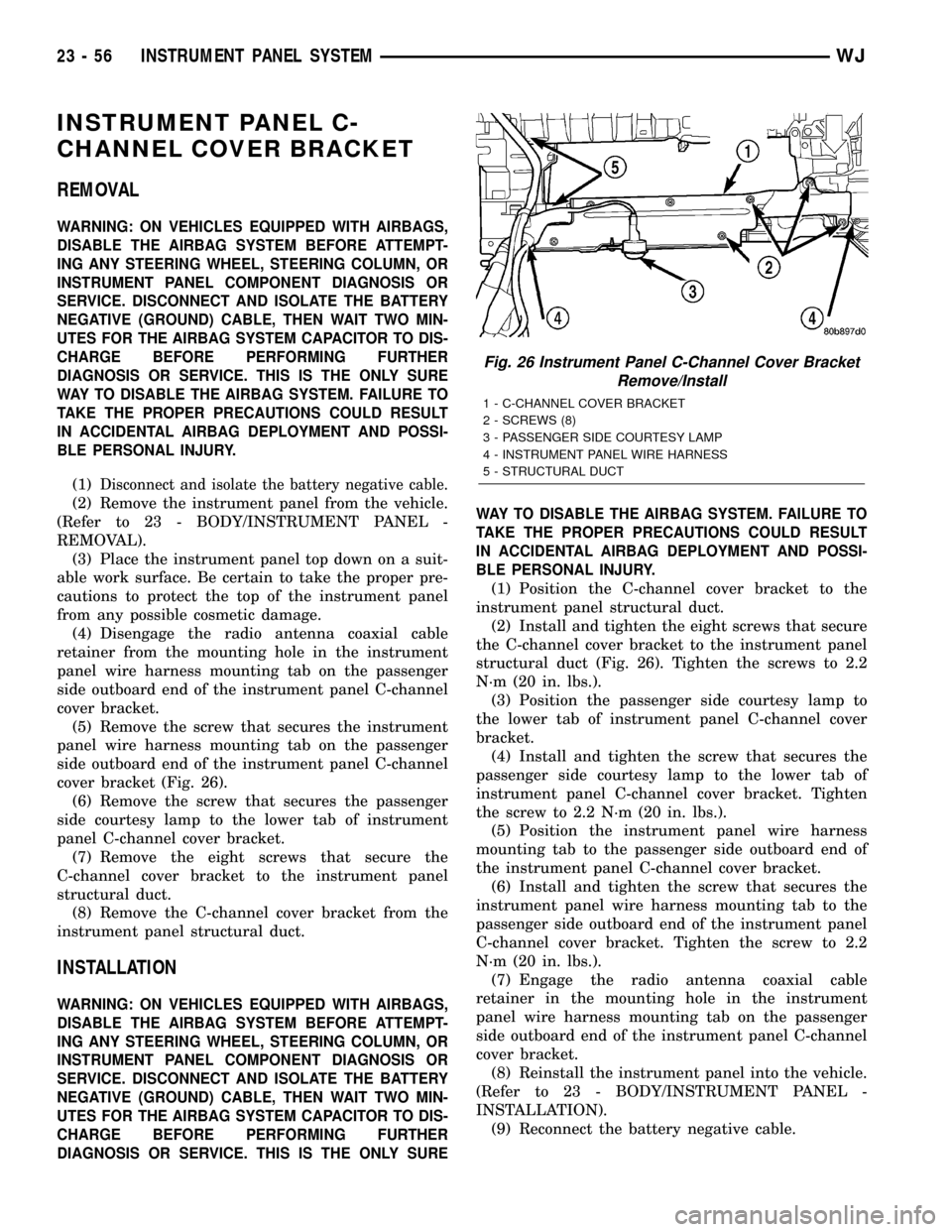
(5) Remove the screw that secures the instrument
panel wire harness mounting tab on the passenger
side outboard end of the instrument panel C-channel
cover bracket (Fig. 26).
(6) Remove the screw that secures the passenger
side courtesy lamp to the lower tab of instrument
panel C-channel cover bracket.
(7) Remove the eight screws that secure the
C-channel cover bracket to the instrument panel
structural duct.
(8) Remove the C-channel cover bracket from the
instrument panel structural duct.
INSTALLATION
WARNING: ON VEHICLES EQUIPPED WITH AIRBAGS,
DISABLE THE AIRBAG SYSTEM BEFORE ATTEMPT-
ING ANY STEERING WHEEL, STEERING COLUMN, OR
INSTRUMENT PANEL COMPONENT DIAGNOSIS OR
SERVICE. DISCONNECT AND ISOLATE THE BATTERY
NEGATIVE (GROUND) CABLE, THEN WAIT TWO MIN-
UTES FOR THE AIRBAG SYSTEM CAPACITOR TO DIS-
CHARGE BEFORE PERFORMING FURTHER
DIAGNOSIS OR SERVICE. THIS IS THE ONLY SUREWAY TO DISABLE THE AIRBAG SYSTEM. FAILURE TO
TAKE THE PROPER PRECAUTIONS COULD RESULT
IN ACCIDENTAL AIRBAG DEPLOYMENT AND POSSI-
BLE PERSONAL INJURY.
(1) Position the C-channel cover bracket to the
instrument panel structural duct.
(2) Install and tighten the eight screws that secure
the C-channel cover bracket to the instrument panel
structural duct (Fig. 26). Tighten the screws to 2.2
N´m (20 in. lbs.).
(3) Position the passenger side courtesy lamp to
the lower tab of instrument panel C-channel cover
bracket.
(4) Install and tighten the screw that secures the
passenger side courtesy lamp to the lower tab of
instrument panel C-channel cover bracket. Tighten
the screw to 2.2 N´m (20 in. lbs.).
(5) Position the instrument panel wire harness
mounting tab to the passenger side outboard end of
the instrument panel C-channel cover bracket.
(6) Install and tighten the screw that secures the
instrument panel wire harness mounting tab to the
passenger side outboard end of the instrument panel
C-channel cover bracket. Tighten the screw to 2.2
N´m (20 in. lbs.).
(7) Engage the radio antenna coaxial cable
retainer in the mounting hole in the instrument
panel wire harness mounting tab on the passenger
side outboard end of the instrument panel C-channel
cover bracket.
(8) Reinstall the instrument panel into the vehicle.
(Refer to 23 - BODY/INSTRUMENT PANEL -
INSTALLATION).
(9) Reconnect the battery negative cable.
Fig. 26 Instrument Panel C-Channel Cover Bracket
Remove/Install
1 - C-CHANNEL COVER BRACKET
2 - SCREWS (8)
3 - PASSENGER SIDE COURTESY LAMP
4 - INSTRUMENT PANEL WIRE HARNESS
5 - STRUCTURAL DUCT
23 - 56 INSTRUMENT PANEL SYSTEMWJ
Page 1930 of 2199
INSTRUMENT PANEL CENTER
BEZEL - LOWER
REMOVAL
WARNING: ON VEHICLES EQUIPPED WITH AIRBAGS,
DISABLE THE AIRBAG SYSTEM BEFORE ATTEMPT-
ING ANY STEERING WHEEL, STEERING COLUMN, OR
INSTRUMENT PANEL COMPONENT DIAGNOSIS OR
SERVICE. DISCONNECT AND ISOLATE THE BATTERY
NEGATIVE (GROUND) CABLE, THEN WAIT TWO MIN-
UTES FOR THE AIRBAG SYSTEM CAPACITOR TO DIS-
CHARGE BEFORE PERFORMING FURTHER
DIAGNOSIS OR SERVICE. THIS IS THE ONLY SURE
WAY TO DISABLE THE AIRBAG SYSTEM. FAILURE TO
TAKE THE PROPER PRECAUTIONS COULD RESULT
IN ACCIDENTAL AIRBAG DEPLOYMENT AND POSSI-
BLE PERSONAL INJURY.
(1) Disconnect and isolate the battery negative
cable.
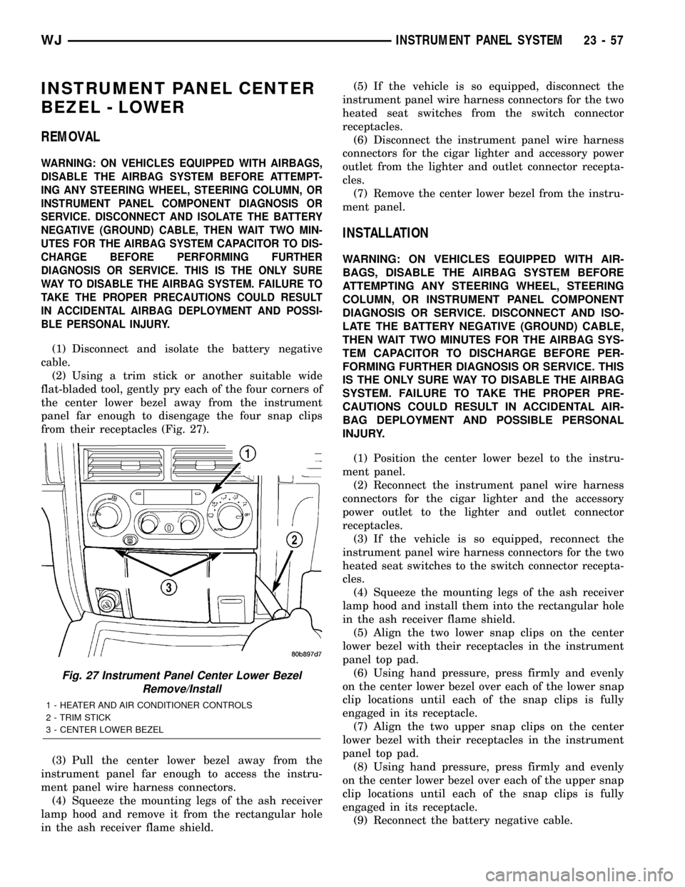
(2) Using a trim stick or another suitable wide
flat-bladed tool, gently pry each of the four corners of
the center lower bezel away from the instrument
panel far enough to disengage the four snap clips
from their receptacles (Fig. 27).
(3) Pull the center lower bezel away from the
instrument panel far enough to access the instru-
ment panel wire harness connectors.
(4) Squeeze the mounting legs of the ash receiver
lamp hood and remove it from the rectangular hole
in the ash receiver flame shield.(5) If the vehicle is so equipped, disconnect the
instrument panel wire harness connectors for the two
heated seat switches from the switch connector
receptacles.
(6) Disconnect the instrument panel wire harness
connectors for the cigar lighter and accessory power
outlet from the lighter and outlet connector recepta-
cles.
(7) Remove the center lower bezel from the instru-
ment panel.
INSTALLATION
WARNING: ON VEHICLES EQUIPPED WITH AIR-
BAGS, DISABLE THE AIRBAG SYSTEM BEFORE
ATTEMPTING ANY STEERING WHEEL, STEERING
COLUMN, OR INSTRUMENT PANEL COMPONENT
DIAGNOSIS OR SERVICE. DISCONNECT AND ISO-
LATE THE BATTERY NEGATIVE (GROUND) CABLE,
THEN WAIT TWO MINUTES FOR THE AIRBAG SYS-
TEM CAPACITOR TO DISCHARGE BEFORE PER-
FORMING FURTHER DIAGNOSIS OR SERVICE. THIS
IS THE ONLY SURE WAY TO DISABLE THE AIRBAG
SYSTEM. FAILURE TO TAKE THE PROPER PRE-
CAUTIONS COULD RESULT IN ACCIDENTAL AIR-
BAG DEPLOYMENT AND POSSIBLE PERSONAL
INJURY.
(1) Position the center lower bezel to the instru-
ment panel.
(2) Reconnect the instrument panel wire harness
connectors for the cigar lighter and the accessory
power outlet to the lighter and outlet connector
receptacles.
(3) If the vehicle is so equipped, reconnect the
instrument panel wire harness connectors for the two
heated seat switches to the switch connector recepta-
cles.
(4) Squeeze the mounting legs of the ash receiver
lamp hood and install them into the rectangular hole
in the ash receiver flame shield.
(5) Align the two lower snap clips on the center
lower bezel with their receptacles in the instrument
panel top pad.
(6) Using hand pressure, press firmly and evenly
on the center lower bezel over each of the lower snap
clip locations until each of the snap clips is fully
engaged in its receptacle.
(7) Align the two upper snap clips on the center
lower bezel with their receptacles in the instrument
panel top pad.
(8) Using hand pressure, press firmly and evenly
on the center lower bezel over each of the upper snap
clip locations until each of the snap clips is fully
engaged in its receptacle.
(9) Reconnect the battery negative cable.
Fig. 27 Instrument Panel Center Lower Bezel
Remove/Install
1 - HEATER AND AIR CONDITIONER CONTROLS
2 - TRIM STICK
3 - CENTER LOWER BEZEL
WJINSTRUMENT PANEL SYSTEM 23 - 57
Page 1935 of 2199
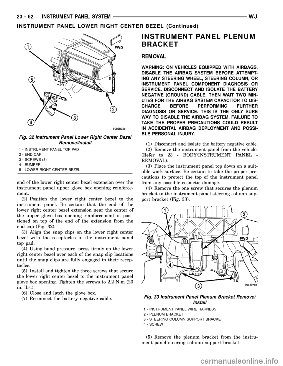
end of the lower right center bezel extension over the
instrument panel upper glove box opening reinforce-
ment.
(2) Position the lower right center bezel to the
instrument panel. Be certain that the end of the
lower right center bezel extension near the center of
the upper glove box opening reinforcement is posi-
tioned on top of the end of the extension from the
end cap (Fig. 32).
(3) Align the snap clips on the lower right center
bezel with the receptacles in the instrument panel
top pad.
(4) Using hand pressure, press firmly on the lower
right center bezel over each of the snap clip locations
until the snap clips are fully engaged in their recep-
tacles.
(5) Install and tighten the three screws that secure
the lower right center bezel to the instrument panel
glove box opening. Tighten the screws to 2.2 N´m (20
in. lbs.).
(6) Close and latch the glove box.
(7) Reconnect the battery negative cable.
INSTRUMENT PANEL PLENUM
BRACKET
REMOVAL
WARNING: ON VEHICLES EQUIPPED WITH AIRBAGS,
DISABLE THE AIRBAG SYSTEM BEFORE ATTEMPT-
ING ANY STEERING WHEEL, STEERING COLUMN, OR
INSTRUMENT PANEL COMPONENT DIAGNOSIS OR
SERVICE. DISCONNECT AND ISOLATE THE BATTERY
NEGATIVE (GROUND) CABLE, THEN WAIT TWO MIN-
UTES FOR THE AIRBAG SYSTEM CAPACITOR TO DIS-
CHARGE BEFORE PERFORMING FURTHER
DIAGNOSIS OR SERVICE. THIS IS THE ONLY SURE
WAY TO DISABLE THE AIRBAG SYSTEM. FAILURE TO
TAKE THE PROPER PRECAUTIONS COULD RESULT
IN ACCIDENTAL AIRBAG DEPLOYMENT AND POSSI-
BLE PERSONAL INJURY.
(1)Disconnect and isolate the battery negative cable.
(2) Remove the instrument panel from the vehicle.
(Refer to 23 - BODY/INSTRUMENT PANEL -
REMOVAL).
(3) Place the instrument panel top down on a suit-
able work surface. Be certain to take the proper pre-
cautions to protect the top of the instrument panel
from any possible cosmetic damage.
(4) Remove the one screw that secures the plenum
bracket to the instrument panel steering column sup-
port bracket (Fig. 33).
(5) Remove the plenum bracket from the instru-
ment panel steering column support bracket.
Fig. 32 Instrument Panel Lower Right Center Bezel
Remove/Install
1 - INSTRUMENT PANEL TOP PAD
2 - END CAP
3 - SCREWS (3)
4 - BUMPER
5 - LOWER RIGHT CENTER BEZEL
Fig. 33 Instrument Panel Plenum Bracket Remove/
Install
1 - INSTRUMENT PANEL WIRE HARNESS
2 - PLENUM BRACKET
3 - STEERING COLUMN SUPPORT BRACKET
4 - SCREW
23 - 62 INSTRUMENT PANEL SYSTEMWJ
INSTRUMENT PANEL LOWER RIGHT CENTER BEZEL (Continued)
Page 1936 of 2199
INSTALLATION
WARNING: ON VEHICLES EQUIPPED WITH AIRBAGS,
DISABLE THE AIRBAG SYSTEM BEFORE ATTEMPT-
ING ANY STEERING WHEEL, STEERING COLUMN, OR
INSTRUMENT PANEL COMPONENT DIAGNOSIS OR
SERVICE. DISCONNECT AND ISOLATE THE BATTERY
NEGATIVE (GROUND) CABLE, THEN WAIT TWO MIN-
UTES FOR THE AIRBAG SYSTEM CAPACITOR TO DIS-
CHARGE BEFORE PERFORMING FURTHER
DIAGNOSIS OR SERVICE. THIS IS THE ONLY SURE
WAY TO DISABLE THE AIRBAG SYSTEM. FAILURE TO
TAKE THE PROPER PRECAUTIONS COULD RESULT
IN ACCIDENTAL AIRBAG DEPLOYMENT AND POSSI-
BLE PERSONAL INJURY.
(1) Position the plenum bracket to the instrument
panel steering column support bracket (Fig. 33).
(2) Install and tighten the one screw that secures
the plenum bracket to the instrument panel steering
column support bracket. Tighten the screw to 11.8
N´m (105 in. lbs.).
(3) Reinstall the instrument panel into the vehicle.
(Refer to 23 - BODY/INSTRUMENT PANEL -
INSTALLATION).
(4) Reconnect the battery negative cable.
INSTRUMENT PANEL
STEERING COLUMN BRACKET
REMOVAL
WARNING: ON VEHICLES EQUIPPED WITH AIRBAGS,
DISABLE THE AIRBAG SYSTEM BEFORE ATTEMPT-
ING ANY STEERING WHEEL, STEERING COLUMN, OR
INSTRUMENT PANEL COMPONENT DIAGNOSIS OR
SERVICE. DISCONNECT AND ISOLATE THE BATTERY
NEGATIVE (GROUND) CABLE, THEN WAIT TWO MIN-
UTES FOR THE AIRBAG SYSTEM CAPACITOR TO DIS-
CHARGE BEFORE PERFORMING FURTHER
DIAGNOSIS OR SERVICE. THIS IS THE ONLY SURE
WAY TO DISABLE THE AIRBAG SYSTEM. FAILURE TO
TAKE THE PROPER PRECAUTIONS COULD RESULT
IN ACCIDENTAL AIRBAG DEPLOYMENT AND POSSI-
BLE PERSONAL INJURY.
(1)Disconnect and isolate the battery negative cable.
(2) Remove the steering column opening cover
from the instrument panel. (Refer to 23 - BODY/IN-
STRUMENT PANEL/STEERING COLUMN OPEN-
ING COVER - REMOVAL).
(3) Remove the four screws that secure the steer-
ing column bracket to the instrument panel steering
column support bracket (Fig. 34).(4) Remove the steering column bracket from the
instrument panel steering column support bracket.
INSTALLATION
WARNING: ON VEHICLES EQUIPPED WITH AIRBAGS,
DISABLE THE AIRBAG SYSTEM BEFORE ATTEMPT-
ING ANY STEERING WHEEL, STEERING COLUMN, OR
INSTRUMENT PANEL COMPONENT DIAGNOSIS OR
SERVICE. DISCONNECT AND ISOLATE THE BATTERY
NEGATIVE (GROUND) CABLE, THEN WAIT TWO MIN-
UTES FOR THE AIRBAG SYSTEM CAPACITOR TO DIS-
CHARGE BEFORE PERFORMING FURTHER
DIAGNOSIS OR SERVICE. THIS IS THE ONLY SURE
WAY TO DISABLE THE AIRBAG SYSTEM. FAILURE TO
TAKE THE PROPER PRECAUTIONS COULD RESULT
IN ACCIDENTAL AIRBAG DEPLOYMENT AND POSSI-
BLE PERSONAL INJURY.
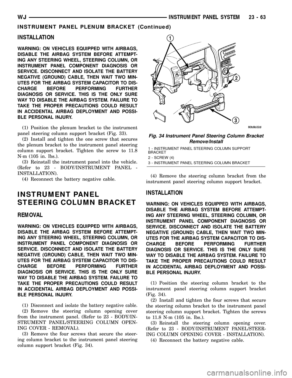
(1) Position the steering column bracket to the
instrument panel steering column support bracket
(Fig. 34).
(2) Install and tighten the four screws that secure
the steering column bracket to the instrument panel
steering column support bracket. Tighten the screws
to 11.8 N´m (105 in. lbs.).
(3)
Reinstall the steering column opening cover.
(Refer to 23 - BODY/INSTRUMENT PANEL/STEER-
ING COLUMN OPENING COVER - INSTALLATION).
(4) Reconnect the battery negative cable.
Fig. 34 Instrument Panel Steering Column Bracket
Remove/Install
1 - INSTRUMENT PANEL STEERING COLUMN SUPPORT
BRACKET
2 - SCREW (4)
3 - INSTRUMENT PANEL STEERING COLUMN BRACKET
WJINSTRUMENT PANEL SYSTEM 23 - 63
INSTRUMENT PANEL PLENUM BRACKET (Continued)