2003 JEEP GRAND CHEROKEE position sensor
[x] Cancel search: position sensorPage 1436 of 2199
(12) Remove first three ignition coils on each bank
(cylinders #1, 3, 5, 2, 4 and 6). Refer to Ignition Coil
Removal/Installation.
(13) Remove 4 fuel rail mounting bolts (Fig. 22).
(14) Gently rock and pullleftside of fuel rail until
fuel injectors just start to clear machined holes in
cylinder head. Gently rock and pullrightside of rail
until injectors just start to clear cylinder head holes.
Repeat this procedure (left/right) until all injectors
have cleared cylinder head holes.
(15) Remove fuel rail (with injectors attached)
from engine.
(16) If fuel injectors are to be removed, refer to
Fuel Injector Removal/Installation.
REMOVAL - 4.0L
The fuel damper is not serviced separately.
WARNING: THE FUEL SYSTEM IS UNDER CON-
STANT FUEL PRESSURE EVEN WITH ENGINE OFF.
THIS PRESSURE MUST BE RELEASED BEFORE
SERVICING FUEL RAIL.
(1) Remove fuel tank filler tube cap.
(2) Perform Fuel System Pressure Release Proce-
dure.
(3) Disconnect negative battery cable from battery.(4) Remove air tube at top of throttle body. Note:
Some engine/vehicles may require removal of air
cleaner ducts at throttle body.
(5) Disconnect electrical connectors at all 6 fuel
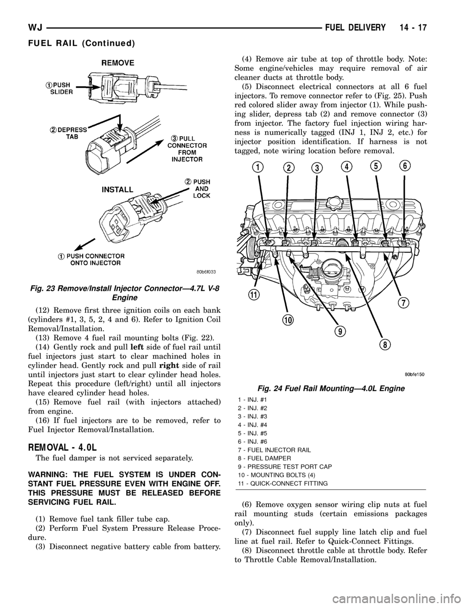
injectors. To remove connector refer to (Fig. 25). Push
red colored slider away from injector (1). While push-
ing slider, depress tab (2) and remove connector (3)
from injector. The factory fuel injection wiring har-
ness is numerically tagged (INJ 1, INJ 2, etc.) for
injector position identification. If harness is not
tagged, note wiring location before removal.
(6) Remove oxygen sensor wiring clip nuts at fuel
rail mounting studs (certain emissions packages
only).
(7) Disconnect fuel supply line latch clip and fuel
line at fuel rail. Refer to Quick-Connect Fittings.
(8) Disconnect throttle cable at throttle body. Refer
to Throttle Cable Removal/Installation.
Fig. 23 Remove/Install Injector ConnectorÐ4.7L V-8
Engine
Fig. 24 Fuel Rail MountingÐ4.0L Engine
1 - INJ. #1
2 - INJ. #2
3 - INJ. #3
4 - INJ. #4
5 - INJ. #5
6 - INJ. #6
7 - FUEL INJECTOR RAIL
8 - FUEL DAMPER
9 - PRESSURE TEST PORT CAP
10 - MOUNTING BOLTS (4)
11 - QUICK-CONNECT FITTING
WJFUEL DELIVERY 14 - 17
FUEL RAIL (Continued)
Page 1437 of 2199

(9) Disconnect speed control cable at throttle body
(if equipped). Refer to Speed Control Cable.
(10) Disconnect automatic transmission cable at
throttle body (if equipped).
(11) Remove cable routing bracket at intake mani-
fold.
(12) Clean dirt/debris from each fuel injector at
intake manifold.
(13) Remove fuel rail mounting nuts/bolts (Fig.
24).
(14) Remove fuel rail by gently rocking until all
fuel injectors have cleared machined holes at intake
manifold.
(15) If fuel injectors are to be removed, refer to
Fuel Injector Removal/Installation.
INSTALLATION
INSTALLATION - 4.7L
(1) If fuel injectors are to be installed, refer to Fuel
Injector Removal/Installation.
(2) Apply a small amount of engine oil to each fuel
injector o-ring. This will help in fuel rail installation.
(3) Position fuel rail/fuel injector assembly to
machined injector openings in cylinder head.
(4) Guide each injector into cylinder head. Be care-
ful not to tear injector o-rings.(5) Pushrightside of fuel rail down until fuel
injectors have bottomed on cylinder head shoulder.
Pushleftfuel rail down until injectors have bot-
tomed on cylinder head shoulder.
(6) Install 4 fuel rail mounting bolts and tighten to
27 N´m (20 ft. lbs.).
(7) Install ignition coils. Refer to Ignition Coil
Removal/Installation.
(8) Connect electrical connectors to throttle body.
(9) Connect electrical connectors to MAP and IAT
sensors.
(10) Connect electrical connectors at all fuel injec-
tors. To install connector, refer to (Fig. 23). Push con-
nector onto injector (1) and then push and lock red
colored slider (2). Verify connector is locked to injec-
tor by lightly tugging on connector.
(11) Connect vacuum lines to throttle body.
(12) Connect fuel line latch clip and fuel line to
fuel rail. Refer to Quick-Connect Fittings.
(13) Connect wiring to rear of generator.
(14) Install air box to throttle body.
(15) Install air duct to air box.
(16) Connect battery cable to battery.
(17) Start engine and check for leaks.
INSTALLATION - 4.0L
(1) If fuel injectors are to be installed, refer to Fuel
Injector Removal/Installation.
(2) Clean each injector bore at intake manifold.
(3) Apply a small amount of clean engine oil to
each injector o-ring. This will aid in installation.
(4) Position tips of all fuel injectors into the corre-
sponding injector bore in intake manifold. Seat injec-
tors into manifold.
(5) Install and tighten fuel rail mounting bolts to
11 3 N´m (100 25 in. lbs.) torque.
(6) Connect electrical connectors at all fuel injec-
tors. To install connector, refer to (Fig. 25). Push con-
nector onto injector (1) and then push and lock red
colored slider (2). Verify connector is locked to injec-
tor by lightly tugging on connector.
(7) Connect fuel line and fuel line latch clip to fuel
rail. Refer Quick-Connect Fittings.
(8) Install protective cap to pressure test port fit-
ting (if equipped).
(9) Install cable routing bracket to intake mani-
fold.
(10) Connect throttle cable at throttle body.
(11) Connect speed control cable at throttle body (if
equipped).
(12) Connect automatic transmission cable at
throttle body (if equipped).
(13) Install oxygen sensor wiring clip nuts to fuel
rail mounting studs (certain emissions packages
only).
Fig. 25 Remove/Install Injector ConnectorÐ4.0L
Engine
14 - 18 FUEL DELIVERYWJ
FUEL RAIL (Continued)
Page 1450 of 2199

FUEL INJECTION
TABLE OF CONTENTS
page page
FUEL INJECTION
DIAGNOSIS AND TESTING
VISUAL INSPECTION..................32
SPECIFICATIONS
TORQUE - FUEL INJECTION.............39
ACCELERATOR PEDAL
REMOVAL.............................39
INSTALLATION.........................39
CRANKSHAFT POSITION SENSOR
DESCRIPTION
DESCRIPTION - 4.0L...................40
DESCRIPTION - 4.7L...................40
OPERATION
OPERATION - 4.0L....................40
OPERATION - 4.7L....................41
REMOVAL
REMOVAL - 4.0L......................41
REMOVAL - 4.7L......................41
INSTALLATION
INSTALLATION - 4.0L..................42
INSTALLATION - 4.7L..................43
FUEL INJECTOR
DESCRIPTION.........................43
OPERATION
OPERATION.........................43
OPERATION - PCM OUTPUT............43
DIAGNOSIS AND TESTING - FUEL INJECTOR . 44
REMOVAL.............................44
INSTALLATION.........................44
FUEL PUMP RELAY
DESCRIPTION.........................44
OPERATION...........................44
IDLE AIR CONTROL MOTOR
DESCRIPTION.........................44
OPERATION...........................44
REMOVAL
REMOVAL - 4.0L......................45
REMOVAL - 4.7L......................45
INSTALLATION
INSTALLATION - 4.0L..................46
INSTALLATION - 4.7L..................46
INTAKE AIR TEMPERATURE SENSOR
DESCRIPTION.........................46
OPERATION...........................46
REMOVAL
REMOVAL - 4.0L......................46
REMOVAL - 4.7L......................46
INSTALLATION
INSTALLATION - 4.0L..................47INSTALLATION - 4.7L..................47
MAP SENSOR
DESCRIPTION
DESCRIPTION........................48
DESCRIPTION - 4.7L...................48
OPERATION...........................48
REMOVAL
REMOVAL - 4.0L......................48
REMOVAL - 4.7L......................49
INSTALLATION
INSTALLATION - 4.0L..................49
INSTALLATION - 4.7L..................49
O2S HEATER RELAY
DESCRIPTION.........................49
OPERATION...........................49
REMOVAL.............................50
INSTALLATION.........................50
O2S SENSOR
DESCRIPTION.........................50
OPERATION...........................50
REMOVAL.............................51
INSTALLATION.........................51
THROTTLE BODY
DESCRIPTION.........................52
OPERATION...........................52
REMOVAL
REMOVAL - 4.0L......................52
REMOVAL - 4.7L......................53
INSTALLATION
INSTALLATION - 4.0L..................53
INSTALLATION - 4.7L..................54
THROTTLE CONTROL CABLE
REMOVAL
REMOVAL - 4.0L......................54
REMOVAL - 4.7L......................55
INSTALLATION
INSTALLATION ± 4.0L..................55
INSTALLATION - 4.7L..................56
THROTTLE POSITION SENSOR
DESCRIPTION.........................56
OPERATION...........................56
REMOVAL
REMOVAL - 4.0L......................57
REMOVAL - 4.7L......................57
INSTALLATION
INSTALLATION - 4.0L..................58
INSTALLATION - 4.7L..................58
WJFUEL INJECTION 14 - 31
Page 1451 of 2199
FUEL INJECTION
DIAGNOSIS AND TESTING
VISUAL INSPECTION
A visual inspection for loose, disconnected or incor-
rectly routed wires, vacuum lines and hoses should
be made. This should be done before attempting to
diagnose or service the fuel injection system. A visual
check will help spot these faults and save unneces-
sary test and diagnostic time. A thorough visual
inspection will include the following checks:
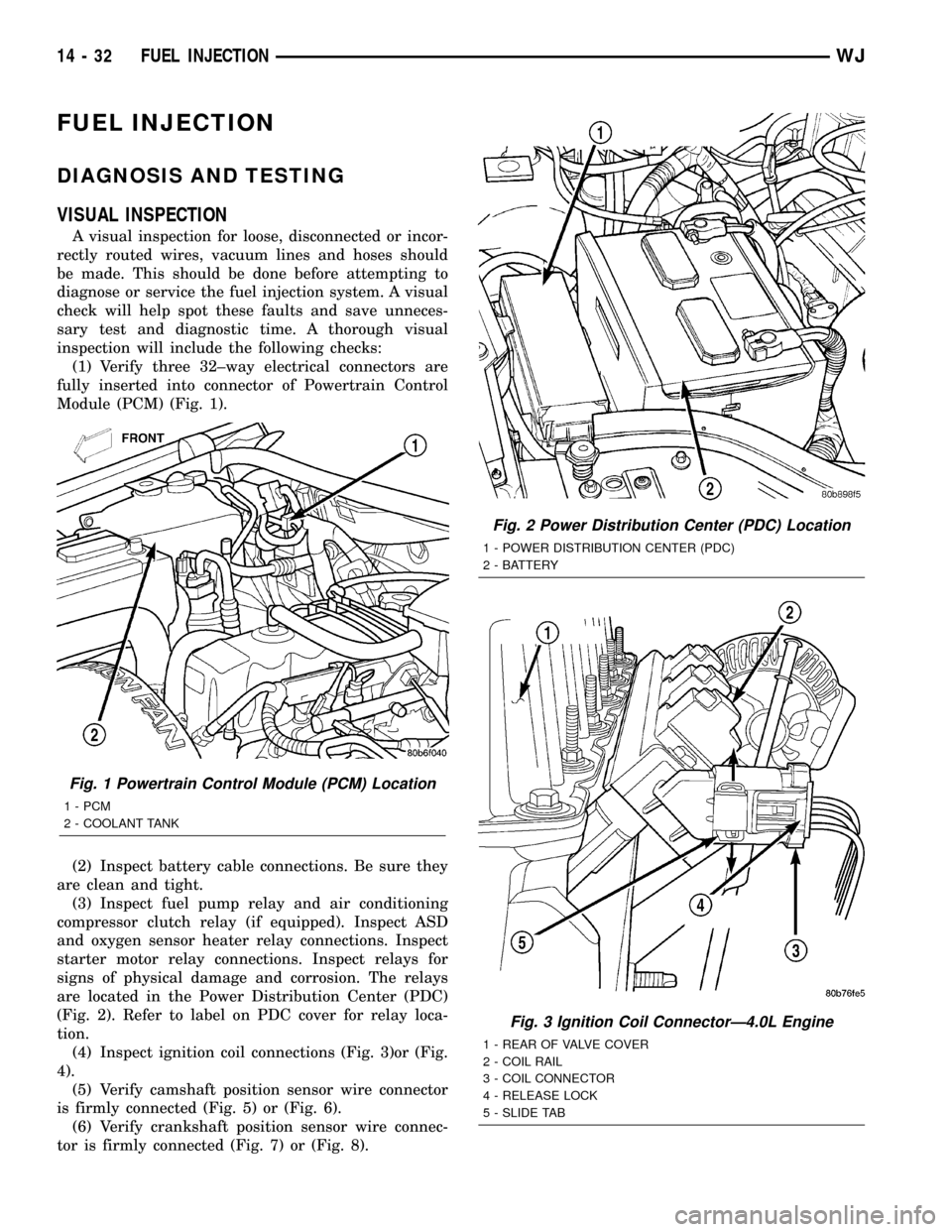
(1) Verify three 32±way electrical connectors are
fully inserted into connector of Powertrain Control
Module (PCM) (Fig. 1).
(2) Inspect battery cable connections. Be sure they
are clean and tight.
(3) Inspect fuel pump relay and air conditioning
compressor clutch relay (if equipped). Inspect ASD
and oxygen sensor heater relay connections. Inspect
starter motor relay connections. Inspect relays for
signs of physical damage and corrosion. The relays
are located in the Power Distribution Center (PDC)
(Fig. 2). Refer to label on PDC cover for relay loca-
tion.
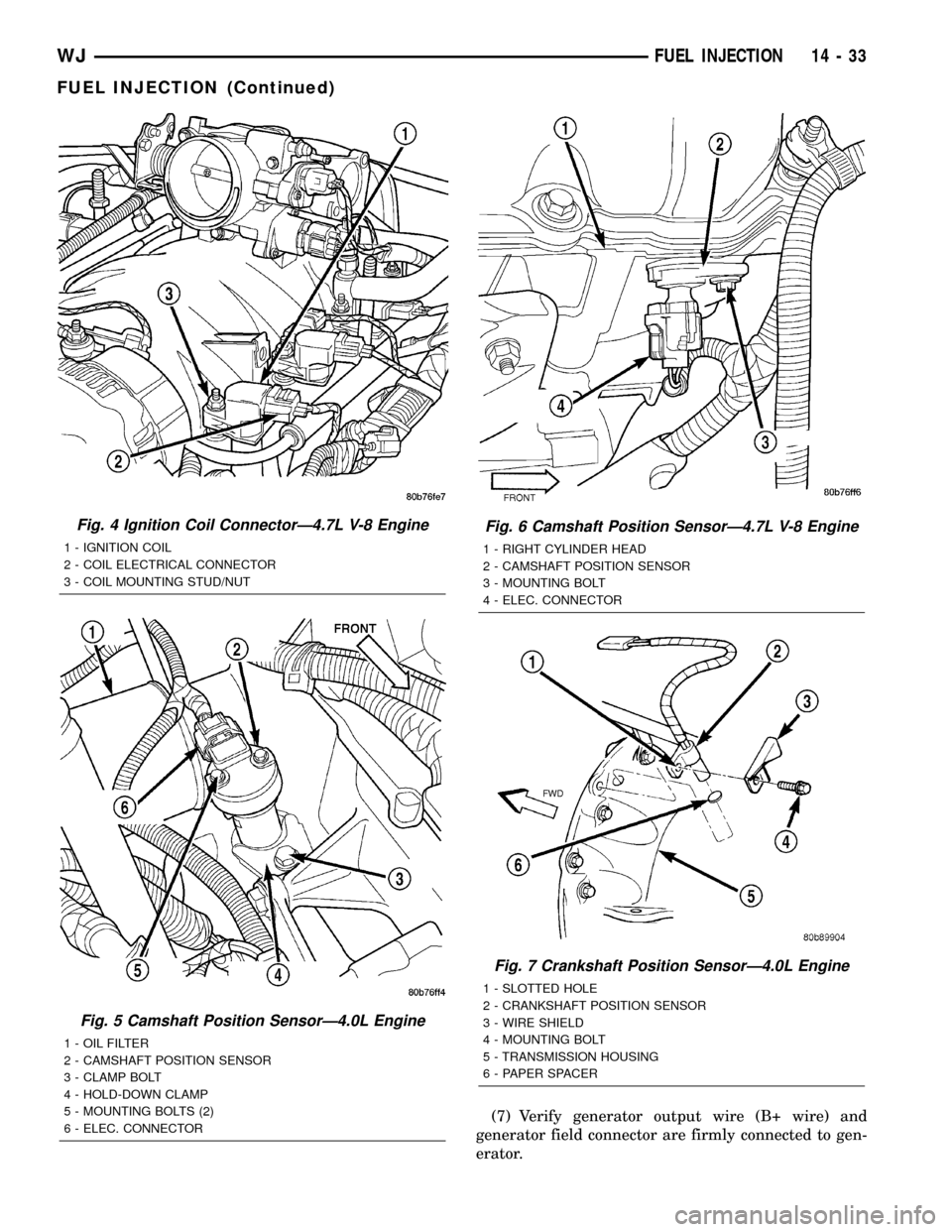
(4) Inspect ignition coil connections (Fig. 3)or (Fig.
4).
(5) Verify camshaft position sensor wire connector
is firmly connected (Fig. 5) or (Fig. 6).
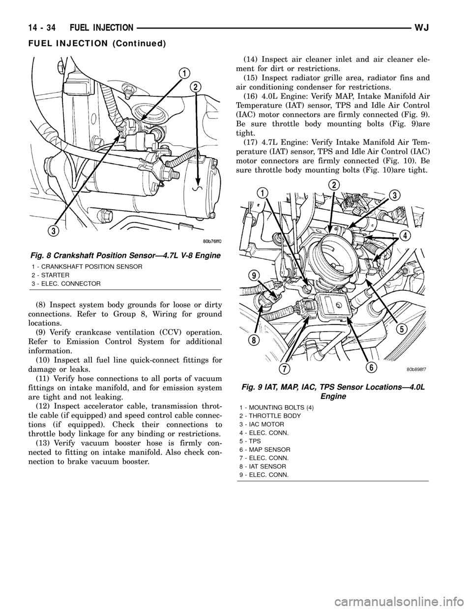
(6) Verify crankshaft position sensor wire connec-
tor is firmly connected (Fig. 7) or (Fig. 8).
Fig. 1 Powertrain Control Module (PCM) Location
1 - PCM
2 - COOLANT TANK
Fig. 2 Power Distribution Center (PDC) Location
1 - POWER DISTRIBUTION CENTER (PDC)
2 - BATTERY
Fig. 3 Ignition Coil ConnectorÐ4.0L Engine
1 - REAR OF VALVE COVER
2 - COIL RAIL
3 - COIL CONNECTOR
4 - RELEASE LOCK
5 - SLIDE TAB
14 - 32 FUEL INJECTIONWJ
Page 1452 of 2199
(7) Verify generator output wire (B+ wire) and
generator field connector are firmly connected to gen-
erator.
Fig. 4 Ignition Coil ConnectorÐ4.7L V-8 Engine
1 - IGNITION COIL
2 - COIL ELECTRICAL CONNECTOR
3 - COIL MOUNTING STUD/NUT
Fig. 5 Camshaft Position SensorÐ4.0L Engine
1 - OIL FILTER
2 - CAMSHAFT POSITION SENSOR
3 - CLAMP BOLT
4 - HOLD-DOWN CLAMP
5 - MOUNTING BOLTS (2)
6 - ELEC. CONNECTOR
Fig. 6 Camshaft Position SensorÐ4.7L V-8 Engine
1 - RIGHT CYLINDER HEAD
2 - CAMSHAFT POSITION SENSOR
3 - MOUNTING BOLT
4 - ELEC. CONNECTOR
Fig. 7 Crankshaft Position SensorÐ4.0L Engine
1 - SLOTTED HOLE
2 - CRANKSHAFT POSITION SENSOR
3 - WIRE SHIELD
4 - MOUNTING BOLT
5 - TRANSMISSION HOUSING
6 - PAPER SPACER
WJFUEL INJECTION 14 - 33
FUEL INJECTION (Continued)
Page 1453 of 2199
(8) Inspect system body grounds for loose or dirty
connections. Refer to Group 8, Wiring for ground
locations.
(9) Verify crankcase ventilation (CCV) operation.
Refer to Emission Control System for additional
information.
(10) Inspect all fuel line quick-connect fittings for
damage or leaks.
(11) Verify hose connections to all ports of vacuum
fittings on intake manifold, and for emission system
are tight and not leaking.
(12) Inspect accelerator cable, transmission throt-
tle cable (if equipped) and speed control cable connec-
tions (if equipped). Check their connections to
throttle body linkage for any binding or restrictions.
(13) Verify vacuum booster hose is firmly con-
nected to fitting on intake manifold. Also check con-
nection to brake vacuum booster.(14) Inspect air cleaner inlet and air cleaner ele-
ment for dirt or restrictions.
(15) Inspect radiator grille area, radiator fins and
air conditioning condenser for restrictions.
(16) 4.0L Engine: Verify MAP, Intake Manifold Air
Temperature (IAT) sensor, TPS and Idle Air Control
(IAC) motor connectors are firmly connected (Fig. 9).
Be sure throttle body mounting bolts (Fig. 9)are
tight.
(17) 4.7L Engine: Verify Intake Manifold Air Tem-
perature (IAT) sensor, TPS and Idle Air Control (IAC)
motor connectors are firmly connected (Fig. 10). Be
sure throttle body mounting bolts (Fig. 10)are tight.
Fig. 8 Crankshaft Position SensorÐ4.7L V-8 Engine
1 - CRANKSHAFT POSITION SENSOR
2-STARTER
3 - ELEC. CONNECTOR
Fig. 9 IAT, MAP, IAC, TPS Sensor LocationsÐ4.0L
Engine
1 - MOUNTING BOLTS (4)
2 - THROTTLE BODY
3 - IAC MOTOR
4 - ELEC. CONN.
5 - TPS
6 - MAP SENSOR
7 - ELEC. CONN.
8 - IAT SENSOR
9 - ELEC. CONN.
14 - 34 FUEL INJECTIONWJ
FUEL INJECTION (Continued)
Page 1459 of 2199
CRANKSHAFT POSITION
SENSOR
DESCRIPTION
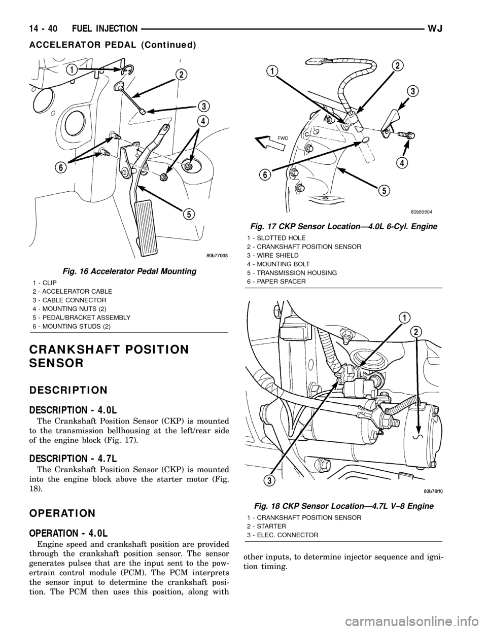
DESCRIPTION - 4.0L
The Crankshaft Position Sensor (CKP) is mounted
to the transmission bellhousing at the left/rear side
of the engine block (Fig. 17).
DESCRIPTION - 4.7L
The Crankshaft Position Sensor (CKP) is mounted
into the engine block above the starter motor (Fig.
18).
OPERATION
OPERATION - 4.0L
Engine speed and crankshaft position are provided
through the crankshaft position sensor. The sensor
generates pulses that are the input sent to the pow-
ertrain control module (PCM). The PCM interprets
the sensor input to determine the crankshaft posi-
tion. The PCM then uses this position, along withother inputs, to determine injector sequence and igni-
tion timing.
Fig. 16 Accelerator Pedal Mounting
1 - CLIP
2 - ACCELERATOR CABLE
3 - CABLE CONNECTOR
4 - MOUNTING NUTS (2)
5 - PEDAL/BRACKET ASSEMBLY
6 - MOUNTING STUDS (2)
Fig. 17 CKP Sensor LocationÐ4.0L 6-Cyl. Engine
1 - SLOTTED HOLE
2 - CRANKSHAFT POSITION SENSOR
3 - WIRE SHIELD
4 - MOUNTING BOLT
5 - TRANSMISSION HOUSING
6 - PAPER SPACER
Fig. 18 CKP Sensor LocationÐ4.7L V±8 Engine
1 - CRANKSHAFT POSITION SENSOR
2-STARTER
3 - ELEC. CONNECTOR
14 - 40 FUEL INJECTIONWJ
ACCELERATOR PEDAL (Continued)
Page 1460 of 2199
The sensor is a hall effect device combined with an
internal magnet. It is also sensitive to steel within a
certain distance from it.
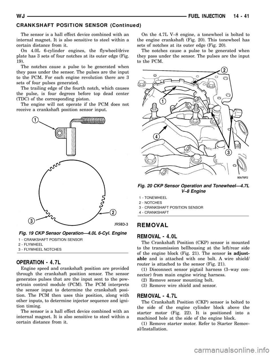
On 4.0L 6-cylinder engines, the flywheel/drive
plate has 3 sets of four notches at its outer edge (Fig.
19).
The notches cause a pulse to be generated when
they pass under the sensor. The pulses are the input
to the PCM. For each engine revolution there are 3
sets of four pulses generated.
The trailing edge of the fourth notch, which causes
the pulse, is four degrees before top dead center
(TDC) of the corresponding piston.
The engine will not operate if the PCM does not
receive a crankshaft position sensor input.
OPERATION - 4.7L
Engine speed and crankshaft position are provided
through the crankshaft position sensor. The sensor
generates pulses that are the input sent to the pow-
ertrain control module (PCM). The PCM interprets
the sensor input to determine the crankshaft posi-
tion. The PCM then uses this position, along with
other inputs, to determine injector sequence and igni-
tion timing.
The sensor is a hall effect device combined with an
internal magnet. It is also sensitive to steel within a
certain distance from it.On the 4.7L V±8 engine, a tonewheel is bolted to
the engine crankshaft (Fig. 20). This tonewheel has
sets of notches at its outer edge (Fig. 20).
The notches cause a pulse to be generated when
they pass under the sensor. The pulses are the input
to the PCM.
REMOVAL
REMOVAL - 4.0L
The Crankshaft Position (CKP) sensor is mounted
to the transmission bellhousing at the left/rear side
of the engine block (Fig. 21). The sensoris adjust-
ableand is attached with one bolt. A wire shield/
router is attached to the sensor (Fig. 21).
(1) Disconnect sensor pigtail harness (3±way con-
nector) from main engine wiring harness.
(2) Remove sensor mounting bolt.
(3) Remove wire shield and sensor.
REMOVAL - 4.7L
The Crankshaft Position (CKP) sensor is bolted to
the side of the engine cylinder block above the
starter motor (Fig. 22). It is positioned into a
machined hole at the side of the engine block.
(1) Remove starter motor. Refer to Starter Remov-
al/Installation.
Fig. 19 CKP Sensor OperationÐ4.0L 6-Cyl. Engine
1 - CRANKSHAFT POSITION SENSOR
2 - FLYWHEEL
3 - FLYWHEEL NOTCHES
Fig. 20 CKP Sensor Operation and TonewheelÐ4.7L
V±8 Engine
1 - TONEWHEEL
2 - NOTCHES
3 - CRANKSHAFT POSITION SENSOR
4 - CRANKSHAFT
WJFUEL INJECTION 14 - 41
CRANKSHAFT POSITION SENSOR (Continued)