2003 JEEP GRAND CHEROKEE Bolts
[x] Cancel search: BoltsPage 1404 of 2199
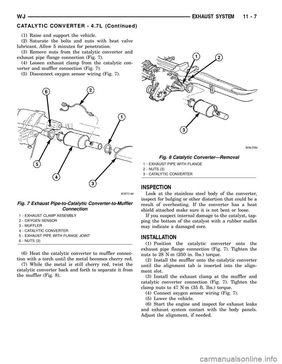
(1) Raise and support the vehicle.
(2) Saturate the bolts and nuts with heat valve
lubricant. Allow 5 minutes for penetration.
(3) Remove nuts from the catalytic converter and
exhaust pipe flange connection (Fig. 7).
(4) Loosen exhaust clamp from the catalytic con-
verter and muffler connection (Fig. 7).
(5) Disconnect oxygen sensor wiring (Fig. 7).
(6) Heat the catalytic converter to muffler connec-
tion with a torch until the metal becomes cherry red.
(7) While the metal is still cherry red, twist the
catalytic converter back and forth to separate it from
the muffler (Fig. 8).
INSPECTION
Look at the stainless steel body of the converter,
inspect for bulging or other distortion that could be a
result of overheating. If the converter has a heat
shield attached make sure it is not bent or loose.
If you suspect internal damage to the catalyst, tap-
ping the bottom of the catalyst with a rubber mallet
may indicate a damaged core.
INSTALLATION
(1) Position the catalytic converter onto the
exhaust pipe flange connection (Fig. 7). Tighten the
nuts to 28 N´m (250 in. lbs.) torque.
(2) Install the muffler onto the catalytic converter
until the alignment tab is inserted into the align-
ment slot.
(3) Install the exhaust clamp at the muffler and
catalytic converter connection (Fig. 7). Tighten the
clamp nuts to 47 N´m (35 ft. lbs.) torque.
(4) Connect oxygen sensor wiring (Fig. 7).
(5) Lower the vehicle.
(6) Start the engine and inspect for exhaust leaks
and exhaust system contact with the body panels.
Adjust the alignment, if needed.
Fig. 7 Exhaust Pipe-to-Catalytic Converter-to-Muffler
Connection
1 - EXHAUST CLAMP ASSEMBLY
2 - OXYGEN SENSOR
3 - MUFFLER
4 - CATALYTIC CONVERTER
5 - EXHAUST PIPE WITH FLANGE JOINT
6 - NUTS (3)
Fig. 8 Catalytic ConverterÐRemoval
1 - EXHAUST PIPE WITH FLANGE
2 - NUTS (3)
3 - CATALYTIC CONVERTER
WJEXHAUST SYSTEM 11 - 7
CATALYTIC CONVERTER - 4.7L (Continued)
Page 1405 of 2199

EXHAUST PIPE - 4.0L
REMOVAL
WARNING: IF TORCHES ARE USED WHEN WORK-
ING ON THE EXHAUST SYSTEM, DO NOT ALLOW
THE FLAME NEAR THE FUEL LINES.
WARNING: THE NORMAL OPERATING TEMPERA-
TURE OF THE EXHAUST SYSTEM IS VERY HIGH.
THEREFORE, NEVER WORK AROUND OR ATTEMPT
TO SERVICE ANY PART OF THE EXHAUST SYSTEM
UNTIL IT IS COOLED. SPECIAL CARE SHOULD BE
TAKEN WHEN WORKING NEAR THE CATALYTIC
CONVERTER. THE TEMPERATURE OF THE CON-
VERTER RISES TO A HIGH LEVEL AFTER A SHORT
PERIOD OF ENGINE OPERATION TIME.
(1) Raise and support the vehicle.(2) Saturate the bolts and nuts with heat valve
lubricant. Allow 5 minutes for penetration.
(3) Remove the oxygen sensor from the exhaust
pipe (Fig. 9).
(4) Remove the nuts from the exhaust pipe to cat-
alytic converter flange connection (Fig. 10).
(5) Disconnect the exhaust pipe from the exhaust
manifold (Fig. 11).
INSPECTION
Discard rusted clamps, broken or worn supports
and attaching parts. Replace a component with orig-
inal equipment parts, or equivalent. This will assure
proper alignment with other parts in the system and
provide acceptable exhaust noise levels.
INSTALLATION
(1) Connect the exhaust pipe to the engine exhaust
manifold. Tighten the nuts to 31 N´m (23 ft. lbs.)
(Fig. 11).
Fig. 9 O2 Sensor Location 4.0L
11 - 8 EXHAUST SYSTEMWJ
Page 1407 of 2199

EXHAUST PIPE - 4.7L
REMOVAL
WARNING: IF TORCHES ARE USED WHEN WORK-
ING ON THE EXHAUST SYSTEM, DO NOT ALLOW
THE FLAME NEAR THE FUEL LINES.
WARNING: THE NORMAL OPERATING TEMPERA-
TURE OF THE EXHAUST SYSTEM IS VERY HIGH.
THEREFORE, NEVER WORK AROUND OR ATTEMPT
TO SERVICE ANY PART OF THE EXHAUST SYSTEM
UNTIL IT IS COOLED. SPECIAL CARE SHOULD BE
TAKEN WHEN WORKING NEAR THE CATALYTIC
CONVERTER. THE TEMPERATURE OF THE CON-
VERTER RISES TO A HIGH LEVEL AFTER A SHORT
PERIOD OF ENGINE OPERATION TIME.
(1) Raise and support the vehicle.(2) Saturate the bolts and nuts with heat valve
lubricant. Allow 5 minutes for penetration.
(3) Remove the oxygen sensor from the exhaust
pipe (Fig. 13).
(4) Remove the retaining nuts holding catalytic
converter to exhaust pipe (Fig. 14).
(5) Disconnect the exhaust pipe from the exhaust
manifold. (Fig. 15)
INSPECTION
Discard rusted clamps, broken or worn supports
and attaching parts. Replace a component with orig-
inal equipment parts, or equivalent. This will assure
proper alignment with other parts in the system and
provide acceptable exhaust noise levels.
INSTALLATION
(1) Connect the exhaust pipe to the engine exhaust
manifold. Tighten the nuts (A) to 31 N´m (23 ft. lbs.)
(Fig. 15).
Fig. 13 4.7L Catalytic Converter and O2 Sensor Configuration - 50 State Emissions
11 - 10 EXHAUST SYSTEMWJ
Page 1408 of 2199
NOTE: When servicing the exhaust system, replace
the factory installed uni-clamp with standard u-bolt
clamps.
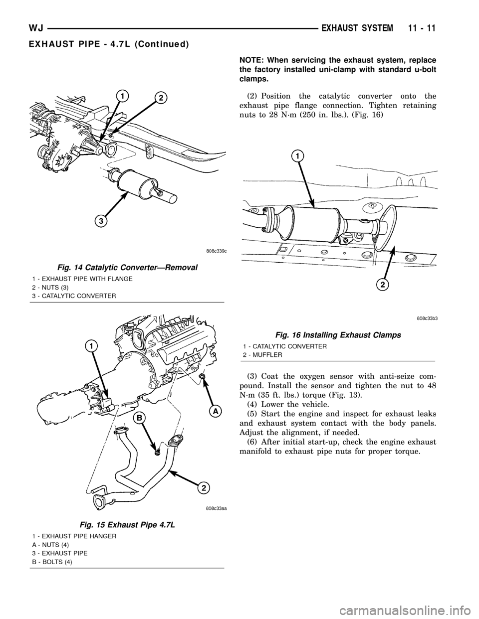
(2) Position the catalytic converter onto the
exhaust pipe flange connection. Tighten retaining
nuts to 28 N´m (250 in. lbs.). (Fig. 16)
(3) Coat the oxygen sensor with anti-seize com-
pound. Install the sensor and tighten the nut to 48
N´m (35 ft. lbs.) torque (Fig. 13).
(4) Lower the vehicle.
(5) Start the engine and inspect for exhaust leaks
and exhaust system contact with the body panels.
Adjust the alignment, if needed.
(6) After initial start-up, check the engine exhaust
manifold to exhaust pipe nuts for proper torque.
Fig. 14 Catalytic ConverterÐRemoval
1 - EXHAUST PIPE WITH FLANGE
2 - NUTS (3)
3 - CATALYTIC CONVERTER
Fig. 15 Exhaust Pipe 4.7L
1 - EXHAUST PIPE HANGER
A - NUTS (4)
3 - EXHAUST PIPE
B - BOLTS (4)
Fig. 16 Installing Exhaust Clamps
1 - CATALYTIC CONVERTER
2 - MUFFLER
WJEXHAUST SYSTEM 11 - 11
EXHAUST PIPE - 4.7L (Continued)
Page 1409 of 2199
HEAT SHIELDS
DESCRIPTION
Heat shields are needed to protect both the vehicle
and the environment from the high temperatures
developed by the catalytic converter. The catalytic
converter releases additional heat into the exhaust
system. Under severe operating conditions, the tem-
perature increases in the area of the converter. Such
conditions can exist when the engine misfires or oth-
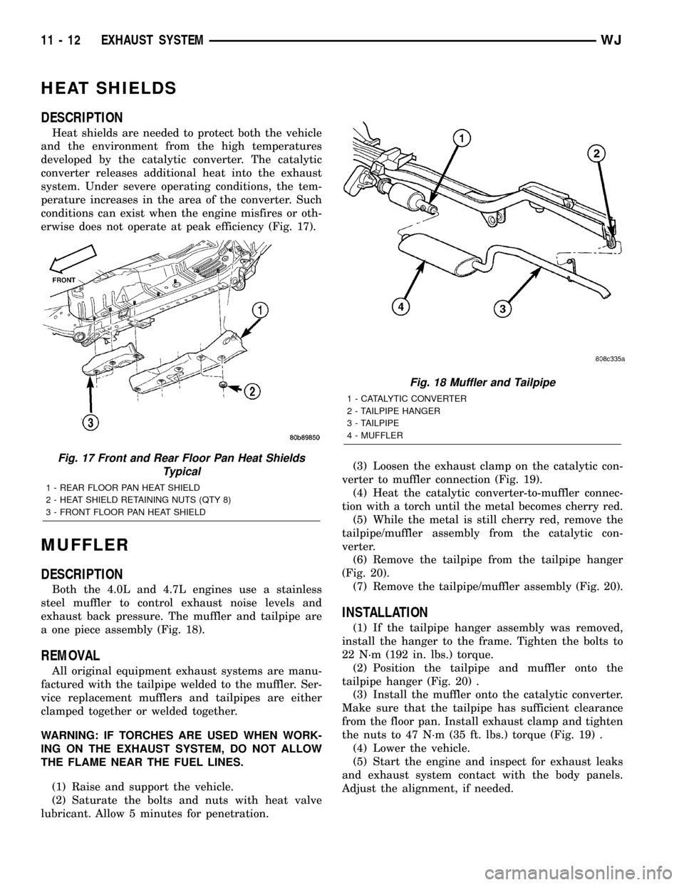
erwise does not operate at peak efficiency (Fig. 17).
MUFFLER
DESCRIPTION
Both the 4.0L and 4.7L engines use a stainless
steel muffler to control exhaust noise levels and
exhaust back pressure. The muffler and tailpipe are
a one piece assembly (Fig. 18).
REMOVAL
All original equipment exhaust systems are manu-
factured with the tailpipe welded to the muffler. Ser-
vice replacement mufflers and tailpipes are either
clamped together or welded together.
WARNING: IF TORCHES ARE USED WHEN WORK-
ING ON THE EXHAUST SYSTEM, DO NOT ALLOW
THE FLAME NEAR THE FUEL LINES.
(1) Raise and support the vehicle.
(2) Saturate the bolts and nuts with heat valve
lubricant. Allow 5 minutes for penetration.(3) Loosen the exhaust clamp on the catalytic con-
verter to muffler connection (Fig. 19).
(4) Heat the catalytic converter-to-muffler connec-
tion with a torch until the metal becomes cherry red.
(5) While the metal is still cherry red, remove the
tailpipe/muffler assembly from the catalytic con-
verter.
(6) Remove the tailpipe from the tailpipe hanger
(Fig. 20).
(7) Remove the tailpipe/muffler assembly (Fig. 20).
INSTALLATION
(1) If the tailpipe hanger assembly was removed,
install the hanger to the frame. Tighten the bolts to
22 N´m (192 in. lbs.) torque.
(2) Position the tailpipe and muffler onto the
tailpipe hanger (Fig. 20) .
(3) Install the muffler onto the catalytic converter.
Make sure that the tailpipe has sufficient clearance
from the floor pan. Install exhaust clamp and tighten
the nuts to 47 N´m (35 ft. lbs.) torque (Fig. 19) .
(4) Lower the vehicle.
(5) Start the engine and inspect for exhaust leaks
and exhaust system contact with the body panels.
Adjust the alignment, if needed.
Fig. 17 Front and Rear Floor Pan Heat Shields
Typical
1 - REAR FLOOR PAN HEAT SHIELD
2 - HEAT SHIELD RETAINING NUTS (QTY 8)
3 - FRONT FLOOR PAN HEAT SHIELD
Fig. 18 Muffler and Tailpipe
1 - CATALYTIC CONVERTER
2 - TAILPIPE HANGER
3 - TAILPIPE
4 - MUFFLER
11 - 12 EXHAUST SYSTEMWJ
Page 1412 of 2199
FRAME & BUMPERS
TABLE OF CONTENTS
page page
FRONT ABSORBER
REMOVAL.............................1
INSTALLATION..........................1
FRONT FASCIA
REMOVAL.............................1
INSTALLATION..........................1
REAR ABSORBER
REMOVAL.............................2
INSTALLATION..........................2
REAR FASCIA
REMOVAL.............................2
INSTALLATION..........................4
FRAME
SPECIFICATIONS
SPECIFICATIONS - TORQUE.............4
FRAME DIMENSIONS...................4
FRONT SKID PLATE
REMOVAL.............................7INSTALLATION..........................7
FRONT TOW HOOK
REMOVAL.............................7
INSTALLATION..........................7
FUEL TANK SKID PLATE
DESCRIPTION..........................7
REAR TOW HOOK
REMOVAL.............................7
INSTALLATION..........................7
TRAILER HITCH
REMOVAL.............................8
INSTALLATION..........................8
TRANSFER CASE SKID PLATE
REMOVAL.............................8
INSTALLATION..........................8
FRONT ABSORBER
REMOVAL
(1) Remove front fascia, refer to (Refer to 13 -
FRAMES & BUMPERS/BUMPERS/FRONT FASCIA
- REMOVAL).
(2) Remove the retainer attaching the absorber to
the fascia.
(3) Separate the absorber from the fascia.
INSTALLATION
(1) Position the absorber on the fascia.
(2) Install the retainer attaching the absorber to
the fascia.
(3) Install front fascia. Refer to (Refer to 13 -
FRAMES & BUMPERS/BUMPERS/FRONT FASCIA
- INSTALLATION).
FRONT FASCIA
REMOVAL
(1) Raise and support vehicle.
(2) Turn front wheels to access rivets and remove
plastic rivets attaching fascia to wheel liner.
(3) Remove bolts attaching fascia to fender (Fig. 1).(4) Remove plastic push pin fasteners attaching
front fascia to lower radiator crossmember splash
shield (Fig. 2).
(5) Disengage fog lamp connectors, if equipped.
(6) Remove screws attaching fascia/grille to upper
radiator crossmember (Fig. 3).
(7) Slide fascia forward to separate from vehicle.
INSTALLATION
(1) Slide fascia onto vehicle engaging fascia with
tabs on bottom of front fenders.
(2) Install screws attaching fascia/grille to upper
radiator crossmember (Fig. 3).
(3) Install bolts attaching fascia to fender (Fig. 1).
(4) Engage fog lamp connectors, if equipped.
(5) Install plastic rivets attaching fascia to wheel
liner.
(6) Install plastic push pin fasteners attaching
front fascia to lower radiator crossmember splash
shield (Fig. 2).
(7) Remove supports and lower vehicle.
WJFRAME & BUMPERS 13 - 1
Page 1415 of 2199
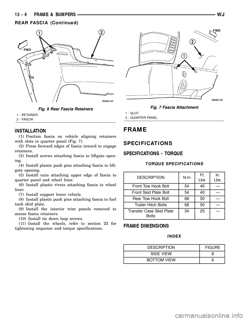
INSTALLATION
(1) Position fascia on vehicle aligning retainers
with slots in quarter panel (Fig. 7).
(2) Press forward edges of fascia inward to engage
retainers.
(3) Install screws attaching fascia to liftgate open-
ing.
(4) Install plastic push pins attaching fascia to lift-
gate opening.
(5) Install nuts attaching upper edge of fascia to
quarter panel and wheel liner.
(6) Install plastic rivets attaching fascia to wheel
liner.
(7) Install support lower vehicle.
(8) Install plastic push pins attaching fascia to fuel
tank skid plate.
(9) Install the interior trim panels removed to
access fascia retainers.
(10) Install tie down loop screws.
(11) Install the wheels, refer to section 22 for
tightening sequence and torque specifications.
FRAME
SPECIFICATIONS
SPECIFICATIONS - TORQUE
TORQUE SPECIFICATIONS
DESCRIPTION N´mFt.
Lbs.In.
Lbs.
Front Tow Hook Bolt 54 40 Ð
Front Skid Plate Bolt 54 40 Ð
Rear Tow Hook Bolt 68 50 Ð
Trailer Hitch Bolts 68 50 Ð
Transfer Case Skid Plate
Bolts34 25 Ð
FRAME DIMENSIONS
INDEX
DESCRIPTION FIGURE
SIDE VIEW 8
BOTTOM VIEW 9
Fig. 6 Rear Fascia Retainers
1 - RETAINER
2 - FASCIA
Fig. 7 Fascia Attachment
1 - SLOT
2 - QUARTER PANEL
13 - 4 FRAME & BUMPERSWJ
REAR FASCIA (Continued)
Page 1418 of 2199
FRONT SKID PLATE
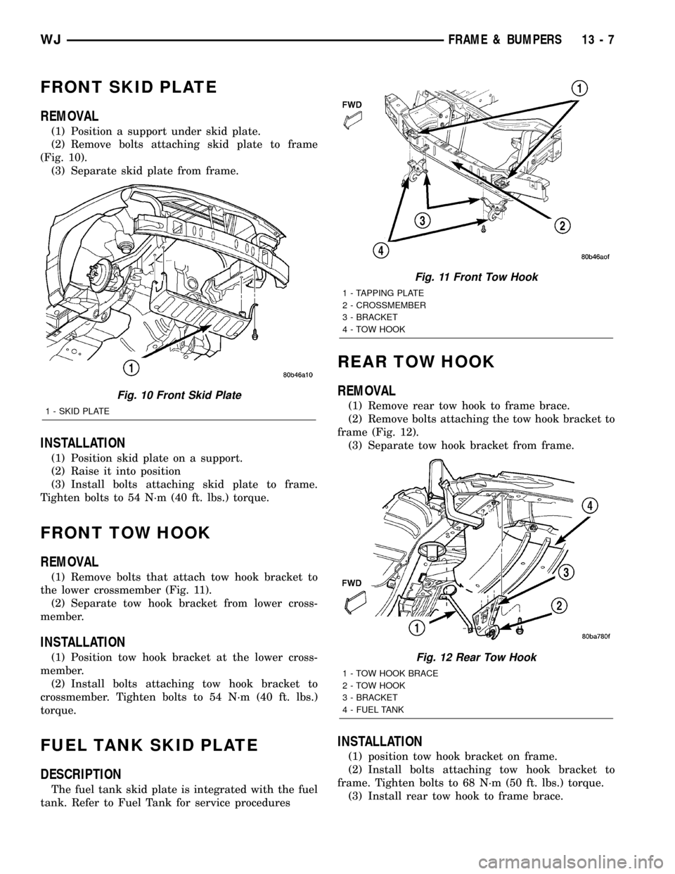
REMOVAL
(1) Position a support under skid plate.
(2) Remove bolts attaching skid plate to frame
(Fig. 10).
(3) Separate skid plate from frame.
INSTALLATION
(1) Position skid plate on a support.
(2) Raise it into position
(3) Install bolts attaching skid plate to frame.
Tighten bolts to 54 N´m (40 ft. lbs.) torque.
FRONT TOW HOOK
REMOVAL
(1) Remove bolts that attach tow hook bracket to
the lower crossmember (Fig. 11).
(2) Separate tow hook bracket from lower cross-
member.
INSTALLATION
(1) Position tow hook bracket at the lower cross-
member.
(2) Install bolts attaching tow hook bracket to
crossmember. Tighten bolts to 54 N´m (40 ft. lbs.)
torque.
FUEL TANK SKID PLATE
DESCRIPTION
The fuel tank skid plate is integrated with the fuel
tank. Refer to Fuel Tank for service procedures
REAR TOW HOOK
REMOVAL
(1) Remove rear tow hook to frame brace.
(2) Remove bolts attaching the tow hook bracket to
frame (Fig. 12).
(3) Separate tow hook bracket from frame.
INSTALLATION
(1) position tow hook bracket on frame.
(2) Install bolts attaching tow hook bracket to
frame. Tighten bolts to 68 N´m (50 ft. lbs.) torque.
(3) Install rear tow hook to frame brace.
Fig. 10 Front Skid Plate
1 - SKID PLATE
Fig. 11 Front Tow Hook
1 - TAPPING PLATE
2 - CROSSMEMBER
3 - BRACKET
4 - TOW HOOK
Fig. 12 Rear Tow Hook
1 - TOW HOOK BRACE
2 - TOW HOOK
3 - BRACKET
4 - FUEL TANK
WJFRAME & BUMPERS 13 - 7