2003 JEEP GRAND CHEROKEE rings
[x] Cancel search: ringsPage 1371 of 2199
ENGINE LUBRICATION FLOW CHARTÐBLOCK: TABLE 1
FROM TO
Oil Pickup Tube Oil Pump
Oil Pump Oil Filter
Oil Filter Block Main Oil Gallery
Block Main Oil Gallery 1. Crankshaft Main Journal
2. Left Cylinder Head*
3. Right Cylinder Head*
Crankshaft Main Journals Crankshaft Rod Journals
Crankshaft Number One Main Journal 1.Front Timing Chain Idler Shaft
2.Both Secondary Chain Tensioners
Left Cylinder Head See Table 2
Right Cylinder Head See Table 2
* The cylinder head
gaskets have an oil restricter to control oil flow to the cylinder heads.
ENGINE LUBRICATION FLOW CHARTÐCYLINDER HEADS: TABLE 2
FROM TO
Cylinder Head Oil Port (in bolt hole) Diagonal Cross Drilling to Main Oil Gallery
Main Oil Gallery (drilled through head from rear to
front)1. Base of Camshaft Towers
2. Lash Adjuster Towers
Base of Camshaft Towers Vertical Drilling Through Tower to Camshaft Bearings**
Lash Adjuster Towers Diagonal Drillings to Hydraulic Lash Adjuster Pockets
** The number three camshaft bearing journal feeds oil into the hollow camshaft tubes. Oil is routed to the intake
lobes, which have oil passages drilled into them to lubricate the rocker arms.
DIAGNOSIS AND TESTING
DIAGNOSIS AND TESTINGÐENGINE OIL
PRESSURE
(1) Remove oil pressure sending unit (Fig. 89)and
install gauge assembly C-3292.
(2) Run engine until thermostat opens.
(3) Oil Pressure:
²Curb IdleÐ25 Kpa (4 psi) minimum
²3000 rpmÐ170 - 550 KPa (25 - 80 psi)
(4) If oil pressure is 0 at idle, shut off engine.
Check for a clogged oil pick-up screen or a pressure
relief valve stuck open.
DIAGNOSIS AND TESTINGÐREAR SEAL AREA
LEAKS
Since it is sometimes difficult to determine the
source of an oil leak in the rear seal area of the
engine, a more involved inspection is necessary. The
following steps should be followed to help pinpoint
the source of the leak.If the leakage occurs at the crankshaft rear oil seal
area:
(1) Disconnect the battery.
(2) Raise the vehicle.
(3) Remove torque converter or clutch housing
cover and inspect rear of block for evidence of oil.
Use a black light to check for the oil leak:
(a) Circular spray pattern generally indicates
seal leakage or crankshaft damage.
(b) Where leakage tends to run straight down,
possible causes are a porous block, distributor seal,
camshaft bore cup plugs, oil galley pipe plugs, oil
filter runoff, and main bearing cap to cylinder
block mating surfaces. See Engine, for proper
repair procedures of these items.
(4) If no leaks are detected, pressurized the crank-
case as outlined in the section, Inspection (Engine oil
Leaks in general)
CAUTION: Do not exceed 20.6 kPa (3 psi).
9 - 128 ENGINE - 4.7LWJ
LUBRICATION (Continued)
Page 1378 of 2199
ASSEMBLY
(1) Wash all parts in a suitable solvent and inspect
carefully for damage or wear.
(2) Install inner and outer rotors
(3) Install oil pump cover plate and install cover
bolts and tighten them to 12 N´m (105 in. lbs.).
(4) Prime oil pump before installation by filling
rotor cavity with engine oil.
(5) If oil pressure is low and pump is within spec-
ifications, inspect for worn engine bearings or other
causes for oil pressure loss.
INSTALLATION
(1) Position the oil pump onto the crankshaft and
install two oil pump retaining bolts.
(2) Position the primary timing chain tensioner
and install the two retaining bolts.
(3) Tighten the oil pump and primary timing chain
tensioner retaining bolts to 28 N´m (250 in. lbs.) in
the sequence shown (Fig. 103).
(4) Install the secondary timing chain tensioners
and timing chains (Refer to 9 - ENGINE/VALVETIMING/TIMING BELT/CHAIN AND SPROCKETS -
INSTALLATION).
(5) Install the timing chain cover (Refer to 9 -
ENGINE/VALVE TIMING/TIMING BELT / CHAIN
COVER(S) - INSTALLATION).
(6) Install the pick-up tube and oil pan (Refer to 9
- ENGINE/LUBRICATION/OIL PAN - INSTALLA-
TION).
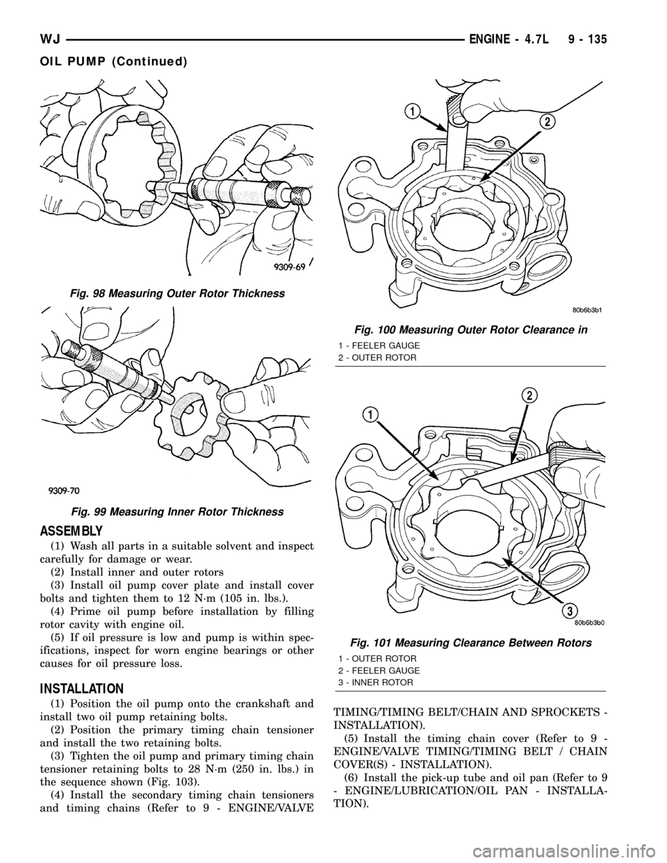
Fig. 98 Measuring Outer Rotor Thickness
Fig. 99 Measuring Inner Rotor Thickness
Fig. 100 Measuring Outer Rotor Clearance in
1 - FEELER GAUGE
2 - OUTER ROTOR
Fig. 101 Measuring Clearance Between Rotors
1 - OUTER ROTOR
2 - FEELER GAUGE
3 - INNER ROTOR
WJENGINE - 4.7L 9 - 135
OIL PUMP (Continued)
Page 1425 of 2199
The regulator is calibrated to maintain fuel system
operating pressure of approximately 339 kPa 34
kPa (49.2 psi 5 psi) at the fuel injectors. It contains
a diaphragm, calibrated springs and a fuel return
valve. The internal fuel filter is also part of the
assembly.
Fuel is supplied to the filter/regulator by the elec-
tric fuel pump. The regulator acts as a check valve to
maintain some fuel pressure when the engine is not
operating. This will help to start the engine. A second
check valve is located at the outlet end of the electric
fuel pump.
If fuel pressure at the pressure regulator exceeds
approximately 49 psi, an internal diaphragm closes.
Excess fuel is then routed into a separate fuel return
line and returned to the fuel tank through the top of
the fuel pump module.
Both fuel filters (at bottom of fuel pump module
and within fuel pressure regulator) are designed for
extended service. They do not require normal sched-
uled maintenance. Filters should only be replaced if
a diagnostic procedure indicates to do so.
REMOVAL
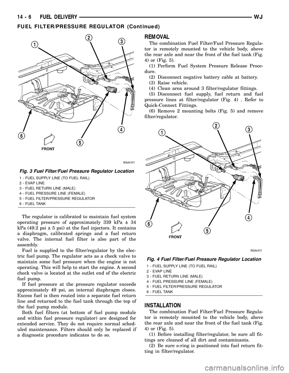
The combination Fuel Filter/Fuel Pressure Regula-
tor is remotely mounted to the vehicle body, above
the rear axle and near the front of the fuel tank (Fig.
4) or (Fig. 5).
(1) Perform Fuel System Pressure Release Proce-
dure.
(2) Disconnect negative battery cable at battery.
(3) Raise vehicle.
(4) Clean area around 3 filter/regulator fittings.
(5) Disconnect fuel supply, fuel return and fuel
pressure lines at filter/regulator (Fig. 4) . Refer to
Quick-Connect Fittings.
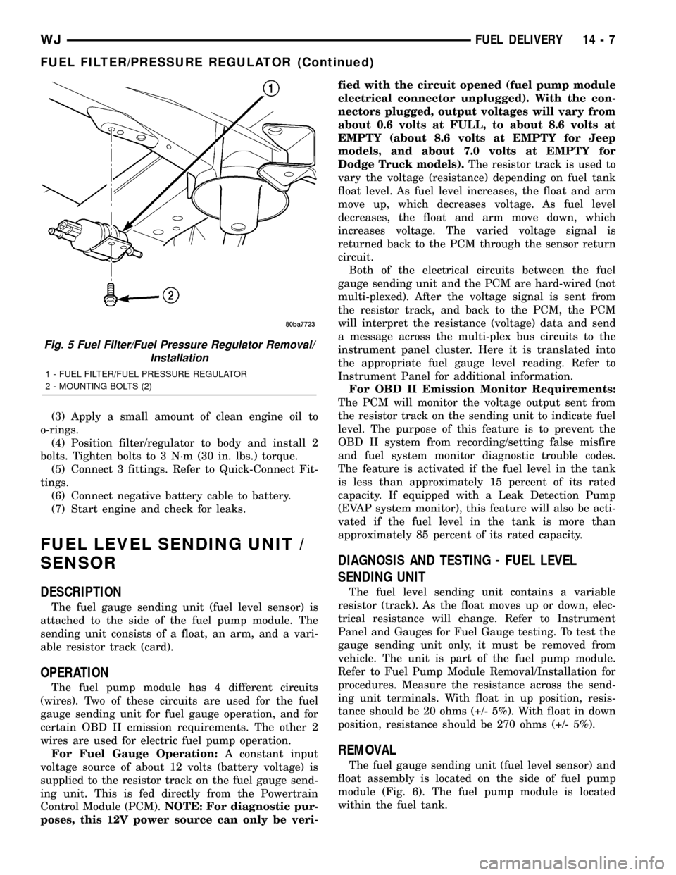
(6) Remove 2 mounting bolts (Fig. 5) and remove
filter/regulator.
INSTALLATION
The combination Fuel Filter/Fuel Pressure Regula-
tor is remotely mounted to the vehicle body, above
the rear axle and near the front of the fuel tank (Fig.
4) or (Fig. 5).
(1) Before installing filter/regulator, be sure all fit-
tings are cleaned of all dirt and contaminants.
(2) Be sure o-ring is positioned into fuel return fit-
ting in filter/regulator.
Fig. 3 Fuel Filter/Fuel Pressure Regulator Location
1 - FUEL SUPPLY LINE (TO FUEL RAIL)
2 - EVAP LINE
3 - FUEL RETURN LINE (MALE)
4 - FUEL PRESSURE LINE (FEMALE)
5 - FUEL FILTER/PRESSURE REGULATOR
6 - FUEL TANK
Fig. 4 Fuel Filter/Fuel Pressure Regulator Location
1 - FUEL SUPPLY LINE (TO FUEL RAIL)
2 - EVAP LINE
3 - FUEL RETURN LINE (MALE)
4 - FUEL PRESSURE LINE (FEMALE)
5 - FUEL FILTER/PRESSURE REGULATOR
6 - FUEL TANK
14 - 6 FUEL DELIVERYWJ
FUEL FILTER/PRESSURE REGULATOR (Continued)
Page 1426 of 2199
(3) Apply a small amount of clean engine oil to
o-rings.
(4) Position filter/regulator to body and install 2
bolts. Tighten bolts to 3 N´m (30 in. lbs.) torque.
(5) Connect 3 fittings. Refer to Quick-Connect Fit-
tings.
(6) Connect negative battery cable to battery.
(7) Start engine and check for leaks.
FUEL LEVEL SENDING UNIT /
SENSOR
DESCRIPTION
The fuel gauge sending unit (fuel level sensor) is
attached to the side of the fuel pump module. The
sending unit consists of a float, an arm, and a vari-
able resistor track (card).
OPERATION
The fuel pump module has 4 different circuits
(wires). Two of these circuits are used for the fuel
gauge sending unit for fuel gauge operation, and for
certain OBD II emission requirements. The other 2
wires are used for electric fuel pump operation.
For Fuel Gauge Operation:A constant input
voltage source of about 12 volts (battery voltage) is
supplied to the resistor track on the fuel gauge send-
ing unit. This is fed directly from the Powertrain
Control Module (PCM).NOTE: For diagnostic pur-
poses, this 12V power source can only be veri-fied with the circuit opened (fuel pump module
electrical connector unplugged). With the con-
nectors plugged, output voltages will vary from
about 0.6 volts at FULL, to about 8.6 volts at
EMPTY (about 8.6 volts at EMPTY for Jeep
models, and about 7.0 volts at EMPTY for
Dodge Truck models).The resistor track is used to
vary the voltage (resistance) depending on fuel tank
float level. As fuel level increases, the float and arm
move up, which decreases voltage. As fuel level
decreases, the float and arm move down, which
increases voltage. The varied voltage signal is
returned back to the PCM through the sensor return
circuit.
Both of the electrical circuits between the fuel
gauge sending unit and the PCM are hard-wired (not
multi-plexed). After the voltage signal is sent from
the resistor track, and back to the PCM, the PCM
will interpret the resistance (voltage) data and send
a message across the multi-plex bus circuits to the
instrument panel cluster. Here it is translated into
the appropriate fuel gauge level reading. Refer to
Instrument Panel for additional information.
For OBD II Emission Monitor Requirements:
The PCM will monitor the voltage output sent from
the resistor track on the sending unit to indicate fuel
level. The purpose of this feature is to prevent the
OBD II system from recording/setting false misfire
and fuel system monitor diagnostic trouble codes.
The feature is activated if the fuel level in the tank
is less than approximately 15 percent of its rated
capacity. If equipped with a Leak Detection Pump
(EVAP system monitor), this feature will also be acti-
vated if the fuel level in the tank is more than
approximately 85 percent of its rated capacity.
DIAGNOSIS AND TESTING - FUEL LEVEL
SENDING UNIT
The fuel level sending unit contains a variable
resistor (track). As the float moves up or down, elec-
trical resistance will change. Refer to Instrument
Panel and Gauges for Fuel Gauge testing. To test the
gauge sending unit only, it must be removed from
vehicle. The unit is part of the fuel pump module.
Refer to Fuel Pump Module Removal/Installation for
procedures. Measure the resistance across the send-
ing unit terminals. With float in up position, resis-
tance should be 20 ohms (+/- 5%). With float in down
position, resistance should be 270 ohms (+/- 5%).
REMOVAL
The fuel gauge sending unit (fuel level sensor) and
float assembly is located on the side of fuel pump
module (Fig. 6). The fuel pump module is located
within the fuel tank.
Fig. 5 Fuel Filter/Fuel Pressure Regulator Removal/
Installation
1 - FUEL FILTER/FUEL PRESSURE REGULATOR
2 - MOUNTING BOLTS (2)
WJFUEL DELIVERY 14 - 7
FUEL FILTER/PRESSURE REGULATOR (Continued)
Page 1437 of 2199
(9) Disconnect speed control cable at throttle body
(if equipped). Refer to Speed Control Cable.
(10) Disconnect automatic transmission cable at
throttle body (if equipped).
(11) Remove cable routing bracket at intake mani-
fold.
(12) Clean dirt/debris from each fuel injector at
intake manifold.
(13) Remove fuel rail mounting nuts/bolts (Fig.
24).
(14) Remove fuel rail by gently rocking until all
fuel injectors have cleared machined holes at intake
manifold.
(15) If fuel injectors are to be removed, refer to
Fuel Injector Removal/Installation.
INSTALLATION
INSTALLATION - 4.7L
(1) If fuel injectors are to be installed, refer to Fuel
Injector Removal/Installation.
(2) Apply a small amount of engine oil to each fuel
injector o-ring. This will help in fuel rail installation.
(3) Position fuel rail/fuel injector assembly to
machined injector openings in cylinder head.
(4) Guide each injector into cylinder head. Be care-
ful not to tear injector o-rings.(5) Pushrightside of fuel rail down until fuel
injectors have bottomed on cylinder head shoulder.
Pushleftfuel rail down until injectors have bot-
tomed on cylinder head shoulder.
(6) Install 4 fuel rail mounting bolts and tighten to
27 N´m (20 ft. lbs.).
(7) Install ignition coils. Refer to Ignition Coil
Removal/Installation.
(8) Connect electrical connectors to throttle body.
(9) Connect electrical connectors to MAP and IAT
sensors.
(10) Connect electrical connectors at all fuel injec-
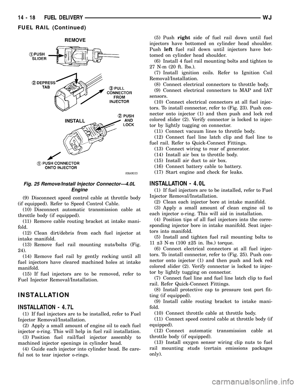
tors. To install connector, refer to (Fig. 23). Push con-
nector onto injector (1) and then push and lock red
colored slider (2). Verify connector is locked to injec-
tor by lightly tugging on connector.
(11) Connect vacuum lines to throttle body.
(12) Connect fuel line latch clip and fuel line to
fuel rail. Refer to Quick-Connect Fittings.
(13) Connect wiring to rear of generator.
(14) Install air box to throttle body.
(15) Install air duct to air box.
(16) Connect battery cable to battery.
(17) Start engine and check for leaks.
INSTALLATION - 4.0L
(1) If fuel injectors are to be installed, refer to Fuel
Injector Removal/Installation.
(2) Clean each injector bore at intake manifold.
(3) Apply a small amount of clean engine oil to
each injector o-ring. This will aid in installation.
(4) Position tips of all fuel injectors into the corre-
sponding injector bore in intake manifold. Seat injec-
tors into manifold.
(5) Install and tighten fuel rail mounting bolts to
11 3 N´m (100 25 in. lbs.) torque.
(6) Connect electrical connectors at all fuel injec-
tors. To install connector, refer to (Fig. 25). Push con-
nector onto injector (1) and then push and lock red
colored slider (2). Verify connector is locked to injec-
tor by lightly tugging on connector.
(7) Connect fuel line and fuel line latch clip to fuel
rail. Refer Quick-Connect Fittings.
(8) Install protective cap to pressure test port fit-
ting (if equipped).
(9) Install cable routing bracket to intake mani-
fold.
(10) Connect throttle cable at throttle body.
(11) Connect speed control cable at throttle body (if
equipped).
(12) Connect automatic transmission cable at
throttle body (if equipped).
(13) Install oxygen sensor wiring clip nuts to fuel
rail mounting studs (certain emissions packages
only).
Fig. 25 Remove/Install Injector ConnectorÐ4.0L
Engine
14 - 18 FUEL DELIVERYWJ
FUEL RAIL (Continued)
Page 1446 of 2199
INLET FILTER
REMOVAL
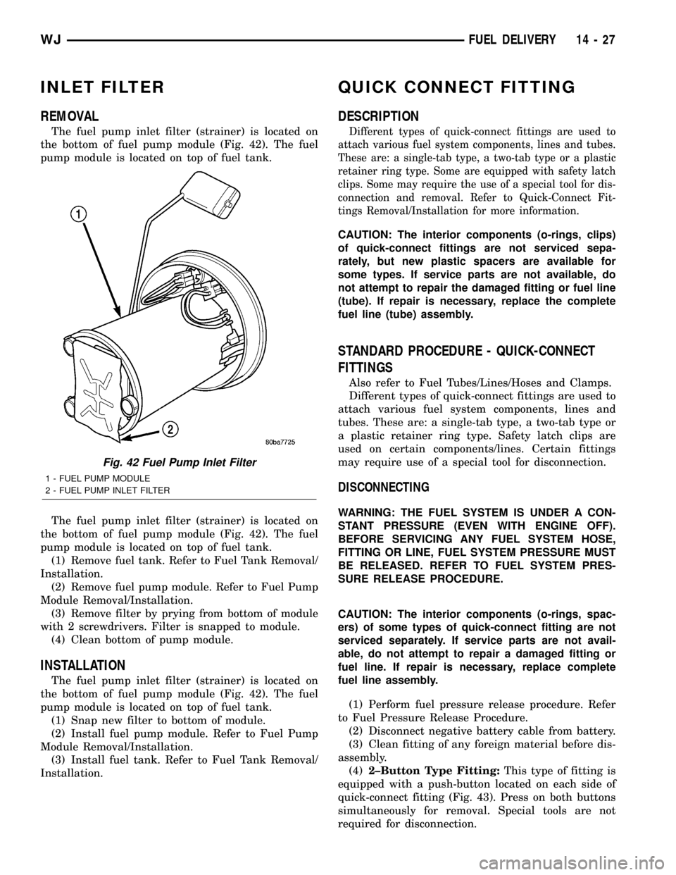
The fuel pump inlet filter (strainer) is located on
the bottom of fuel pump module (Fig. 42). The fuel
pump module is located on top of fuel tank.
The fuel pump inlet filter (strainer) is located on
the bottom of fuel pump module (Fig. 42). The fuel
pump module is located on top of fuel tank.
(1) Remove fuel tank. Refer to Fuel Tank Removal/
Installation.
(2) Remove fuel pump module. Refer to Fuel Pump
Module Removal/Installation.
(3) Remove filter by prying from bottom of module
with 2 screwdrivers. Filter is snapped to module.
(4) Clean bottom of pump module.
INSTALLATION
The fuel pump inlet filter (strainer) is located on
the bottom of fuel pump module (Fig. 42). The fuel
pump module is located on top of fuel tank.
(1) Snap new filter to bottom of module.
(2) Install fuel pump module. Refer to Fuel Pump
Module Removal/Installation.
(3) Install fuel tank. Refer to Fuel Tank Removal/
Installation.
QUICK CONNECT FITTING
DESCRIPTION
Different types of quick-connect fittings are used to
attach various fuel system components, lines and tubes.
These are: a single-tab type, a two-tab type or a plastic
retainer ring type. Some are equipped with safety latch
clips. Some may require the use of a special tool for dis-
connection and removal. Refer to Quick-Connect Fit-
tings Removal/Installation for more information.
CAUTION: The interior components (o-rings, clips)
of quick-connect fittings are not serviced sepa-
rately, but new plastic spacers are available for
some types. If service parts are not available, do
not attempt to repair the damaged fitting or fuel line
(tube). If repair is necessary, replace the complete
fuel line (tube) assembly.
STANDARD PROCEDURE - QUICK-CONNECT
FITTINGS
Also refer to Fuel Tubes/Lines/Hoses and Clamps.
Different types of quick-connect fittings are used to
attach various fuel system components, lines and
tubes. These are: a single-tab type, a two-tab type or
a plastic retainer ring type. Safety latch clips are
used on certain components/lines. Certain fittings
may require use of a special tool for disconnection.
DISCONNECTING
WARNING: THE FUEL SYSTEM IS UNDER A CON-
STANT PRESSURE (EVEN WITH ENGINE OFF).
BEFORE SERVICING ANY FUEL SYSTEM HOSE,
FITTING OR LINE, FUEL SYSTEM PRESSURE MUST
BE RELEASED. REFER TO FUEL SYSTEM PRES-
SURE RELEASE PROCEDURE.
CAUTION: The interior components (o-rings, spac-
ers) of some types of quick-connect fitting are not
serviced separately. If service parts are not avail-
able, do not attempt to repair a damaged fitting or
fuel line. If repair is necessary, replace complete
fuel line assembly.
(1) Perform fuel pressure release procedure. Refer
to Fuel Pressure Release Procedure.
(2) Disconnect negative battery cable from battery.
(3) Clean fitting of any foreign material before dis-
assembly.
(4)2±Button Type Fitting:This type of fitting is
equipped with a push-button located on each side of
quick-connect fitting (Fig. 43). Press on both buttons
simultaneously for removal. Special tools are not
required for disconnection.
Fig. 42 Fuel Pump Inlet Filter
1 - FUEL PUMP MODULE
2 - FUEL PUMP INLET FILTER
WJFUEL DELIVERY 14 - 27
Page 1447 of 2199
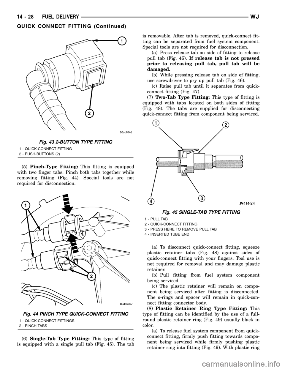
(5)Pinch-Type Fitting:This fitting is equipped
with two finger tabs. Pinch both tabs together while
removing fitting (Fig. 44). Special tools are not
required for disconnection.
(6)Single-Tab Type Fitting:This type of fitting
is equipped with a single pull tab (Fig. 45). The tabis removable. After tab is removed, quick-connect fit-
ting can be separated from fuel system component.
Special tools are not required for disconnection.
(a) Press release tab on side of fitting to release
pull tab (Fig. 46).If release tab is not pressed
prior to releasing pull tab, pull tab will be
damaged.
(b) While pressing release tab on side of fitting,
use screwdriver to pry up pull tab (Fig. 46).
(c) Raise pull tab until it separates from quick-
connect fitting (Fig. 47).
(7)Two-Tab Type Fitting:This type of fitting is
equipped with tabs located on both sides of fitting
(Fig. 48). The tabs are supplied for disconnecting
quick-connect fitting from component being serviced.
(a) To disconnect quick-connect fitting, squeeze
plastic retainer tabs (Fig. 48) against sides of
quick-connect fitting with your fingers. Tool use is
not required for removal and may damage plastic
retainer.
(b) Pull fitting from fuel system component
being serviced.
(c) The plastic retainer will remain on compo-
nent being serviced after fitting is disconnected.
The o-rings and spacer will remain in quick-con-
nect fitting connector body.
(8)Plastic Retainer Ring Type Fitting:This
type of fitting can be identified by the use of a full-
round plastic retainer ring (Fig. 49) usually black in
color.
(a) To release fuel system component from quick-
connect fitting, firmly push fitting towards compo-
nent being serviced while firmly pushing plastic
retainer ring into fitting (Fig. 49). With plastic ring
Fig. 43 2-BUTTON TYPE FITTING
1 - QUICK-CONNECT FITTING
2 - PUSH-BUTTONS (2)
Fig. 44 PINCH TYPE QUICK-CONNECT FITTING
1 - QUICK-CONNECT FITTINGS
2 - PINCH TABS
Fig. 45 SINGLE-TAB TYPE FITTING
1 - PULL TAB
2 - QUICK-CONNECT FITTING
3 - PRESS HERE TO REMOVE PULL TAB
4 - INSERTED TUBE END
14 - 28 FUEL DELIVERYWJ
QUICK CONNECT FITTING (Continued)
Page 1481 of 2199
LOOSE STEERING AND VEHICLE LEADS/DRIFTS
CONDITION POSSIBLE CAUSE CORRECTION
EXCESSIVE PLAY IN STEERING
WHEEL1. Worn or loose suspension or
steering components.1. Repair as necessary.
2. Worn or loose wheel bearings. 2. Repair as necessary.
3. Steering gear mounting. 3. Tighten gear mounting bolts to
specification.
4. Gear out of adjustment. 4. Adjust gear to specification.
5. Worn or loose steering coupler. 5. Repair as necessary.
VEHICLE PULLS TO ONE SIDE
DURING BRAKING1. Tire Pressure. 1. Adjust tire pressure.
2. Air in brake hydrauliics system. 2. Bleed brake system.
3. Worn brake components. 3. Repair as necessary.
VEHICLE LEADS OR DRIFTS
FROM STRAIGHT AHEAD
DIRECTION ON UNCROWNED
ROAD.1. Tire pressure. 1. Adjust tire pressure.
2. Radial tire lead. 2. Cross front tires.
3. Brakes dragging. 3. Repair as necessary.
4. Wheel alignment. 4. Align vehicle.
5. Weak or broken spring. 5. Replace spring.
6. Loose or worn steering/
suspension components.6. Repair as necessary.
7. Cross caster out of spec. 7. Adjust or replace axle as
necessary.
DIAGNOSIS AND TESTING - STEERING FLOW
AND PRESSURE
The following procedure is used to test the opera-
tion of the power steering system on the vehicle. This
test will provide the gallons per minute (GPM) or
flow rate of the power steering pump along with the
maximum relief pressure. Perform test any time a
power steering system problem is present. This test
will determine if the power steering pump or power
steering gear is not functioning properly. The follow-
ing pressure and flow test is performed using Power
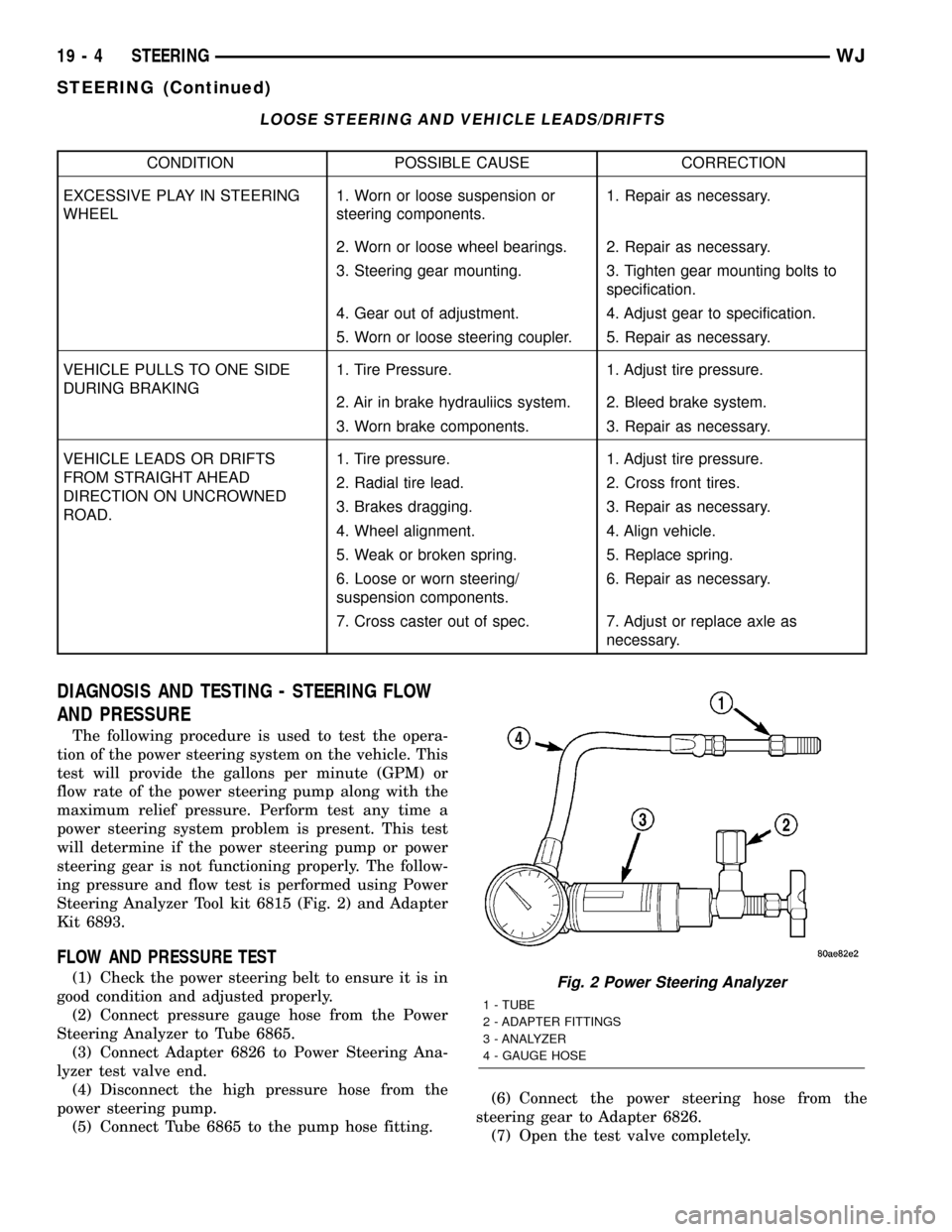
Steering Analyzer Tool kit 6815 (Fig. 2) and Adapter
Kit 6893.
FLOW AND PRESSURE TEST
(1) Check the power steering belt to ensure it is in
good condition and adjusted properly.
(2) Connect pressure gauge hose from the Power
Steering Analyzer to Tube 6865.
(3) Connect Adapter 6826 to Power Steering Ana-
lyzer test valve end.
(4) Disconnect the high pressure hose from the
power steering pump.
(5) Connect Tube 6865 to the pump hose fitting.(6) Connect the power steering hose from the
steering gear to Adapter 6826.
(7) Open the test valve completely.Fig. 2 Power Steering Analyzer
1 - TUBE
2 - ADAPTER FITTINGS
3 - ANALYZER
4 - GAUGE HOSE
19 - 4 STEERINGWJ
STEERING (Continued)