2003 JEEP GRAND CHEROKEE bolt pattern
[x] Cancel search: bolt patternPage 107 of 2199

the shim thickness required on the pinion side of the
housing.
(24) Rotate dial indicator out of the way on pilot
stud.
(25) Remove differential case and dummy bearings
from the housing.
(26) Install side bearings and cups on differential
case.(27) Install spreader W-129-B utilizing some items
from Adapter Set 6987, on the housing and spread
axle opening enough to receive differential case.
CAUTION: Never spread over 0.38 mm (0.015 in.). If
housing is over-spread, it could be distorted or
damaged.
(28) Place the bearing preload shims in the hous-
ing, against the axle tubes.
(29) Install differential case into the housing.
(30) Remove spreader from the housing.
(31) Install differential bearing caps in their origi-
nal locations.
(32) Install bearing cap bolts and tighten to 77
N´m (57 ft. lbs.).
(33) Rotate the differential case several times to
seat the side bearings.
(34) Position the indicator plunger against a ring
gear tooth (Fig. 22).
(35) Push and hold ring gear upward while not
allowing the pinion gear to rotate.
(36) Zero dial indicator face to pointer.
(37) Push and hold ring gear downward while not
allowing the pinion gear to rotate. Dial indicator
reading should be between 0.12-0.20 mm (0.005-0.008
in.). If backlash is not within specifications transfer
the necessary amount of shim thickness from one
side of the axle housing to the other (Fig. 23).
(38) Verify differential case and ring gear runout
by measuring ring to pinion gear backlash at eight
locations around the ring gear. Readings should not
vary more than 0.05 mm (0.002 in.). If readings vary
more than specified, the ring gear or the differential
case is defective.
After the proper backlash is achieved, perform
Gear Contact Pattern Analysis procedure.
Fig. 20 ZERO DIAL INDICATOR
1 - DIAL INDICATOR FACE
2 - FORCE DIFFERENTIAL CASE TO PINION GEAR SIDE
3 - PINION GEAR
4 - DIFFERENTIAL HOUSING
5 - DIFFERENTIAL CASE
Fig. 21 DIFFERENTIAL TO RING GEAR SIDE
1 - DIAL INDICATOR
2 - FORCE DIFFERENTIAL CASE TO RING GEAR SIDE
3 - PINION GEAR
4 - DIFFERENTIAL HOUSING
5 - DIFFERENTIAL CASE
Fig. 22 RING GEAR BACKLASH MEASUREMENT
1 - DIAL INDICATOR
3 - 62 REAR AXLE - 198RBIWJ
REAR AXLE - 198RBI (Continued)
Page 108 of 2199
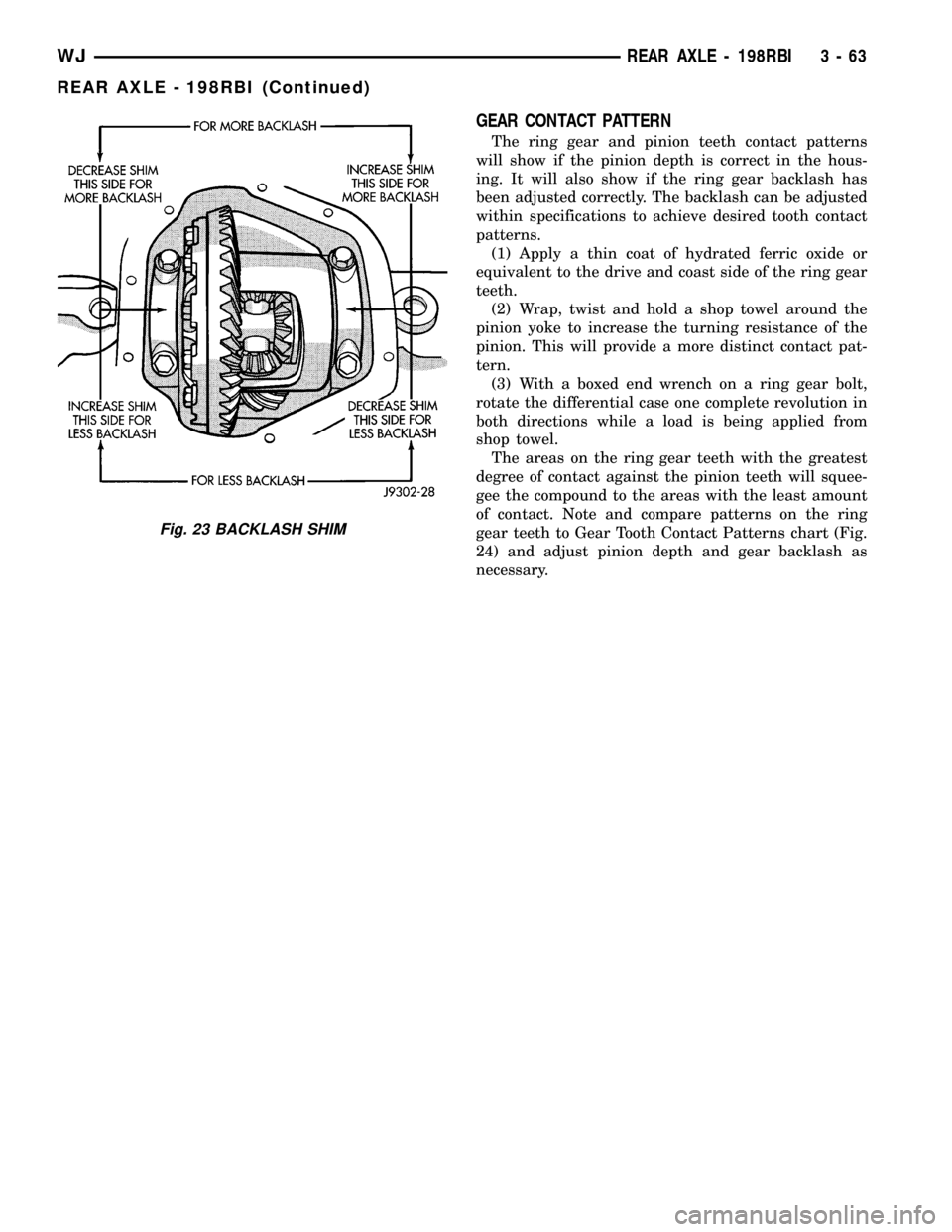
GEAR CONTACT PATTERN
The ring gear and pinion teeth contact patterns
will show if the pinion depth is correct in the hous-
ing. It will also show if the ring gear backlash has
been adjusted correctly. The backlash can be adjusted
within specifications to achieve desired tooth contact
patterns.
(1) Apply a thin coat of hydrated ferric oxide or
equivalent to the drive and coast side of the ring gear
teeth.
(2) Wrap, twist and hold a shop towel around the
pinion yoke to increase the turning resistance of the
pinion. This will provide a more distinct contact pat-
tern.
(3) With a boxed end wrench on a ring gear bolt,
rotate the differential case one complete revolution in
both directions while a load is being applied from
shop towel.
The areas on the ring gear teeth with the greatest
degree of contact against the pinion teeth will squee-
gee the compound to the areas with the least amount
of contact. Note and compare patterns on the ring
gear teeth to Gear Tooth Contact Patterns chart (Fig.
24) and adjust pinion depth and gear backlash as
necessary.
Fig. 23 BACKLASH SHIM
WJREAR AXLE - 198RBI 3 - 63
REAR AXLE - 198RBI (Continued)
Page 124 of 2199
(12) Install cover and tighten bolts in a criss-cross
pattern to 41 N´m (30 ft. lbs.).
(13) Refill the differential with Mopar Hypoid
Gear Lubricant or equivalent to bottom of the fill
plug hole.
(14) Install fill hole plug.
(15) Remove support and lower the vehicle.
DIFFERENTIAL-TRAC-LOC
DIAGNOSIS AND TESTING
The most common problem is a chatter noise when
turning corners. Before removing the unit for repair,
drain, flush and refill the axle with the specified
lubricant. A container of Mopar Trac-loktLubricant
(friction modifier) should be added after repair ser-
vice or during a lubricant change.
After changing the lubricant, drive the vehicle and
make 10 to 12 slow, figure-eight turns. This maneu-
ver will pump lubricant through the clutches. This
will correct the condition in most instances. If the
chatter persists, clutch damage could have occurred.
DIFFERENTIAL TEST
The differential can be tested without removing the
differential case by measuring rotating torque. Make
sure brakes are not dragging during this measure-
ment.
(1) Place blocks in front and rear of both front
wheels.
(2) Raise one rear wheel until it is completely off
the ground.
(3) Engine off, transmission in neutral, and park-
ing brake off.
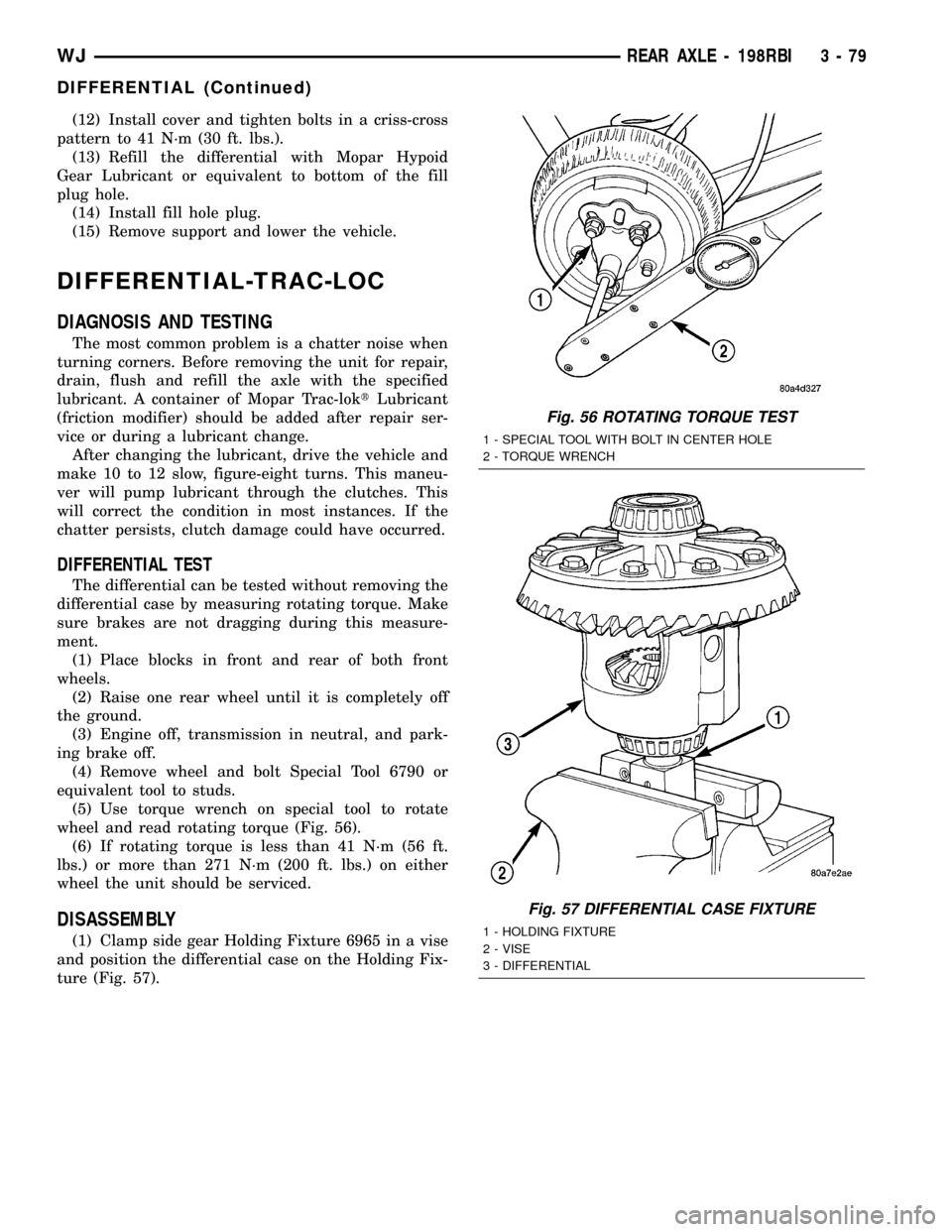
(4) Remove wheel and bolt Special Tool 6790 or
equivalent tool to studs.
(5) Use torque wrench on special tool to rotate
wheel and read rotating torque (Fig. 56).
(6) If rotating torque is less than 41 N´m (56 ft.
lbs.) or more than 271 N´m (200 ft. lbs.) on either
wheel the unit should be serviced.
DISASSEMBLY
(1) Clamp side gear Holding Fixture 6965 in a vise
and position the differential case on the Holding Fix-
ture (Fig. 57).
Fig. 56 ROTATING TORQUE TEST
1 - SPECIAL TOOL WITH BOLT IN CENTER HOLE
2 - TORQUE WRENCH
Fig. 57 DIFFERENTIAL CASE FIXTURE
1 - HOLDING FIXTURE
2 - VISE
3 - DIFFERENTIAL
WJREAR AXLE - 198RBI 3 - 79
DIFFERENTIAL (Continued)
Page 140 of 2199

Condition Possible Causes Correction
Gear Teeth Broke 1. Overloading. 1. Replace gears. Examine other
gears and bearings for possible
damage.
2. Erratic clutch operation. 2. Replace gears and examine the
remaining parts for damage. Avoid
erratic clutch operation.
3. Ice-spotted pavement. 3. Replace gears and examine
remaining parts for damage.
4. Improper adjustments. 4. Replace gears and examine
remaining parts for damage. Ensure
ring gear backlash is correct.
Axle Noise 1. Insufficient lubricant. 1. Fill differential with the correct
fluid type and quantity.
2. Improper ring gear and pinion
adjustment.2. Check ring gear and pinion
contact pattern.
3. Unmatched ring gear and pinion. 3. Replace gears with a matched
ring gear and pinion.
4. Worn teeth on ring gear and/or
pinion.4. Replace ring gear and pinion.
5. Loose pinion bearings. 5. Adjust pinion bearing pre-load.
6. Loose differential bearings. 6. Adjust differential bearing
pre-load.
7. Mis-aligned or sprung ring gear. 7. Measure ring gear run-out.
Replace components as necessary.
8. Loose differential bearing cap
bolts.8. Inspect differential components
and replace as necessary. Ensure
that the bearing caps are torqued
tot he proper specification.
9. Housing not machined properly. 9. Replace housing.
VARI-LOKT
(1) Park the vehicle on a level surface or raise
vehicle on hoist so that the vehicle is level.
(2) Remove the axle fill plug.
(3) Verify that the axle fluid level is correct. The
fluid level is correct if the fluid is level with the bot-
tom of the fill hole.
(4) Shift the transfer case into the 4WD full-time
position.
(5) Drive the vehicle in a tight circle for 2 minutes
at 5mph to fully prime the pump.
(6) Block the tires opposite the axle to be tested to
prevent the vehicle from moving.
(7) Shift the transfer case into the 4WD Low posi-
tion and the transmission into the Park position.
(8) Raise both the wheels of the axle to be tested
off of the ground.(9) Rotate the left wheel by hand at a minimum of
one revolution per second while an assistant rotates
the right wheel in the opposite direction.
(10) The left wheel should spin freely at first and
then increase in resistance within 5 revolutions until
the wheels cannot be continuously rotated in opposite
directions.
(11) The Vari-loktdifferential has engaged prop-
erly if the wheels cannot be rotated in opposite direc-
tions for a moment. After the wheels stop rotating for
a moment, the fluid pressure will drop in the differ-
ential and the wheels begin to rotate once again.
(12) If the system does not operate properly,
replace the Vari-loktdifferential.
REMOVAL
(1) Raise and support the vehicle.
(2) Position a lifting device under the axle and
secure axle.
WJREAR AXLE - 226RBA 3 - 95
REAR AXLE - 226RBA (Continued)
Page 148 of 2199
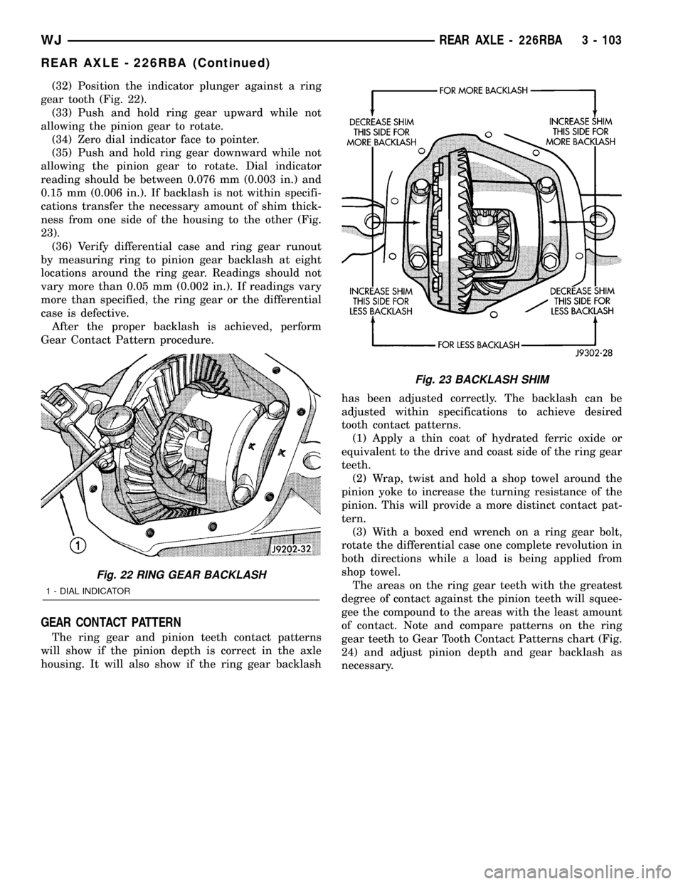
(32) Position the indicator plunger against a ring
gear tooth (Fig. 22).
(33) Push and hold ring gear upward while not
allowing the pinion gear to rotate.
(34) Zero dial indicator face to pointer.
(35) Push and hold ring gear downward while not
allowing the pinion gear to rotate. Dial indicator
reading should be between 0.076 mm (0.003 in.) and
0.15 mm (0.006 in.). If backlash is not within specifi-
cations transfer the necessary amount of shim thick-
ness from one side of the housing to the other (Fig.
23).
(36) Verify differential case and ring gear runout
by measuring ring to pinion gear backlash at eight
locations around the ring gear. Readings should not
vary more than 0.05 mm (0.002 in.). If readings vary
more than specified, the ring gear or the differential
case is defective.
After the proper backlash is achieved, perform
Gear Contact Pattern procedure.
GEAR CONTACT PATTERN
The ring gear and pinion teeth contact patterns
will show if the pinion depth is correct in the axle
housing. It will also show if the ring gear backlashhas been adjusted correctly. The backlash can be
adjusted within specifications to achieve desired
tooth contact patterns.
(1) Apply a thin coat of hydrated ferric oxide or
equivalent to the drive and coast side of the ring gear
teeth.
(2) Wrap, twist and hold a shop towel around the
pinion yoke to increase the turning resistance of the
pinion. This will provide a more distinct contact pat-
tern.
(3) With a boxed end wrench on a ring gear bolt,
rotate the differential case one complete revolution in
both directions while a load is being applied from
shop towel.
The areas on the ring gear teeth with the greatest
degree of contact against the pinion teeth will squee-
gee the compound to the areas with the least amount
of contact. Note and compare patterns on the ring
gear teeth to Gear Tooth Contact Patterns chart (Fig.
24) and adjust pinion depth and gear backlash as
necessary.
Fig. 22 RING GEAR BACKLASH
1 - DIAL INDICATOR
Fig. 23 BACKLASH SHIM
WJREAR AXLE - 226RBA 3 - 103
REAR AXLE - 226RBA (Continued)
Page 164 of 2199
(12) Install cover and tighten bolts in a criss-cross
pattern to 41 N´m (30 ft. lbs.).
(13) Refill the differential with Mopar Hypoid
Gear Lubricant or equivalent to bottom of the fill
plug hole.
(14) Install fill hole plug.
(15) Remove support and lower the vehicle.
DIFFERENTIAL - TRAC-LOK
DIAGNOSIS AND TESTING
The most common problem is a chatter noise when
turning corners. Before removing the unit for repair,
drain, flush and refill the axle with the specified
lubricant. A container of Mopar Trac-loktLubricant
(friction modifier) should be added after repair ser-
vice or during a lubricant change.
After changing the lubricant, drive the vehicle and
make 10 to 12 slow, figure-eight turns. This maneu-
ver will pump lubricant through the clutches. This
will correct the condition in most instances. If the
chatter persists, clutch damage could have occurred.
DIFFERENTIAL TEST
The differential can be tested without removing the
differential case by measuring rotating torque. Make
sure brakes are not dragging during this measure-
ment.
(1) Place blocks in front and rear of both front
wheels.
(2) Raise one rear wheel until it is completely off
the ground.
(3) Engine off, transmission in neutral, and park-
ing brake off.
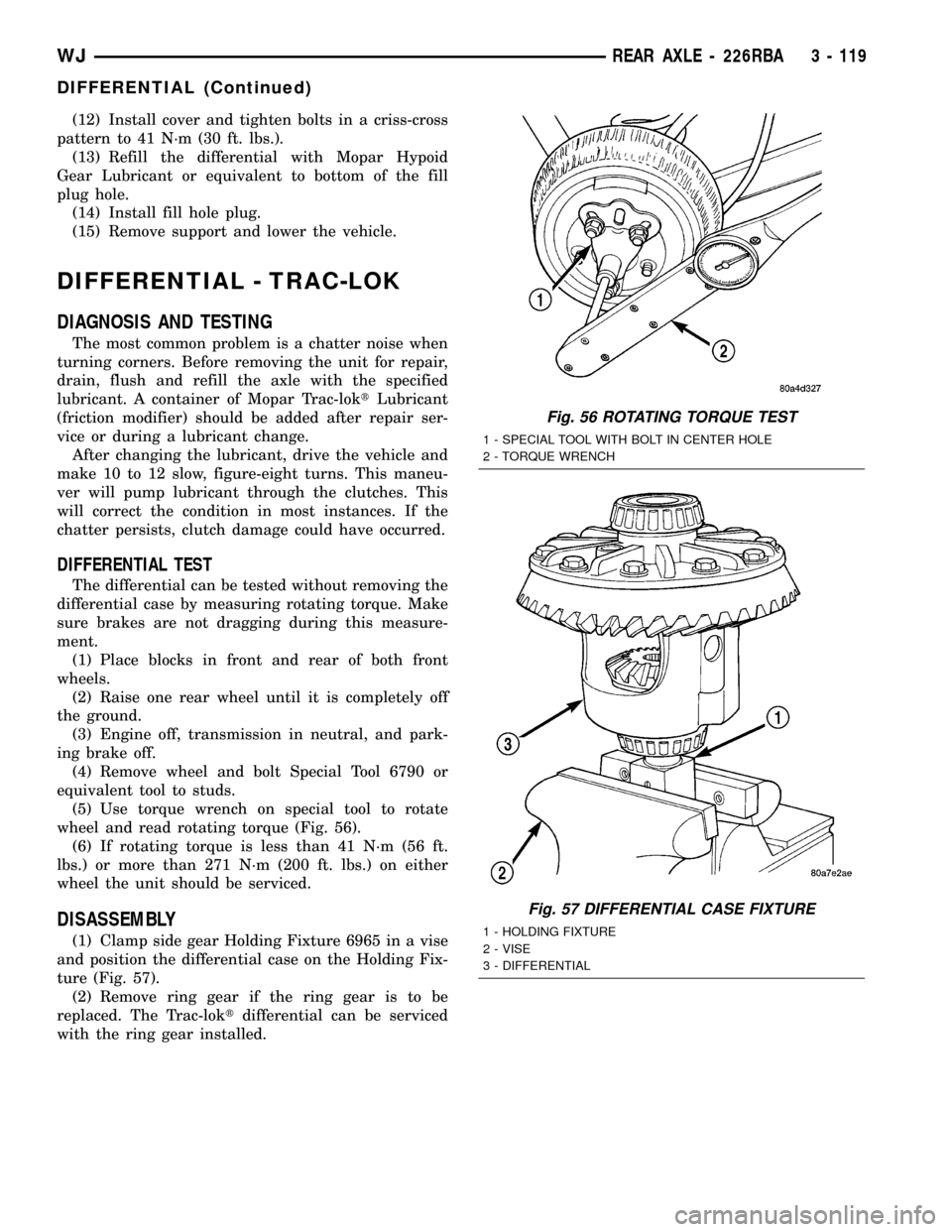
(4) Remove wheel and bolt Special Tool 6790 or
equivalent tool to studs.
(5) Use torque wrench on special tool to rotate
wheel and read rotating torque (Fig. 56).
(6) If rotating torque is less than 41 N´m (56 ft.
lbs.) or more than 271 N´m (200 ft. lbs.) on either
wheel the unit should be serviced.
DISASSEMBLY
(1) Clamp side gear Holding Fixture 6965 in a vise
and position the differential case on the Holding Fix-
ture (Fig. 57).
(2) Remove ring gear if the ring gear is to be
replaced. The Trac-loktdifferential can be serviced
with the ring gear installed.
Fig. 56 ROTATING TORQUE TEST
1 - SPECIAL TOOL WITH BOLT IN CENTER HOLE
2 - TORQUE WRENCH
Fig. 57 DIFFERENTIAL CASE FIXTURE
1 - HOLDING FIXTURE
2 - VISE
3 - DIFFERENTIAL
WJREAR AXLE - 226RBA 3 - 119
DIFFERENTIAL (Continued)
Page 174 of 2199
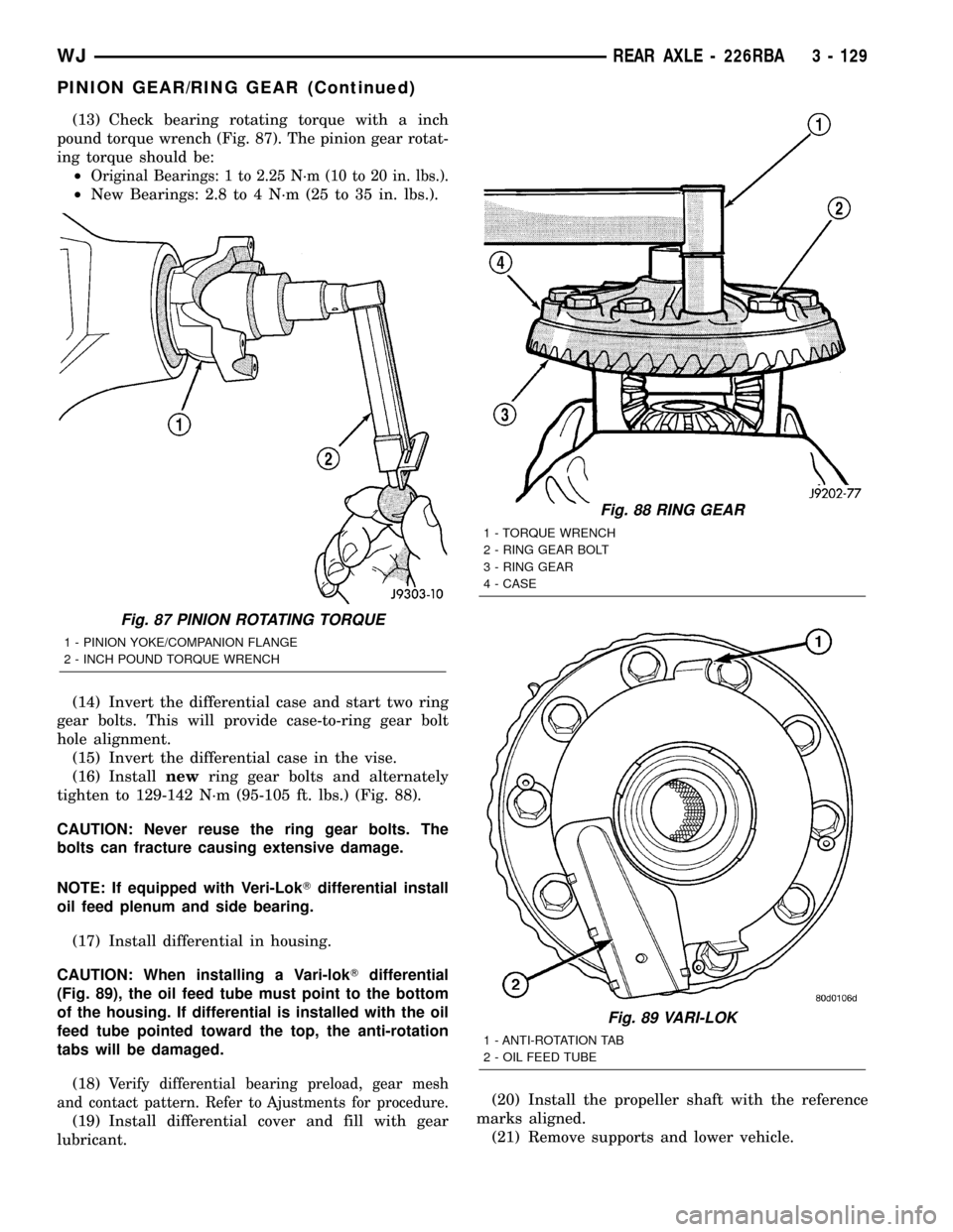
(13) Check bearing rotating torque with a inch
pound torque wrench (Fig. 87). The pinion gear rotat-
ing torque should be:
²
Original Bearings: 1 to 2.25 N´m (10 to 20 in. lbs.).
²New Bearings: 2.8 to 4 N´m (25 to 35 in. lbs.).
(14) Invert the differential case and start two ring
gear bolts. This will provide case-to-ring gear bolt
hole alignment.
(15) Invert the differential case in the vise.
(16) Installnewring gear bolts and alternately
tighten to 129-142 N´m (95-105 ft. lbs.) (Fig. 88).
CAUTION: Never reuse the ring gear bolts. The
bolts can fracture causing extensive damage.
NOTE: If equipped with Veri-LokTdifferential install
oil feed plenum and side bearing.
(17) Install differential in housing.
CAUTION: When installing a Vari-lokTdifferential
(Fig. 89), the oil feed tube must point to the bottom
of the housing. If differential is installed with the oil
feed tube pointed toward the top, the anti-rotation
tabs will be damaged.
(18)
Verify differential bearing preload, gear mesh
and contact pattern. Refer to Ajustments for procedure.
(19) Install differential cover and fill with gear
lubricant.(20) Install the propeller shaft with the reference
marks aligned.
(21) Remove supports and lower vehicle.
Fig. 87 PINION ROTATING TORQUE
1 - PINION YOKE/COMPANION FLANGE
2 - INCH POUND TORQUE WRENCH
Fig. 88 RING GEAR
1 - TORQUE WRENCH
2 - RING GEAR BOLT
3 - RING GEAR
4 - CASE
Fig. 89 VARI-LOK
1 - ANTI-ROTATION TAB
2 - OIL FEED TUBE
WJREAR AXLE - 226RBA 3 - 129
PINION GEAR/RING GEAR (Continued)
Page 240 of 2199

(3) Install drive belt (Refer to 7 - COOLING/AC-
CESSORY DRIVE/DRIVE BELTS - INSTALLA-
TION).
(4) Check belt indexing marks (Refer to 7 - COOL-
ING/ACCESSORY DRIVE/DRIVE BELTS - INSTAL-
LATION).
INSTALLATIONÐ4.0L ENGINE
(1) Install tensioner assembly to mounting
bracket, align the two dowels on the tensioner with
the mounting bracket and hand start the bolt.
Tighten bolt to 28 N´m (250 in. lbs.).
CAUTION: To prevent damage to coil case, coil
mounting bolts must be torqued.
(2) Install drive belt. (Refer to 7 - COOLING/AC-
CESSORY DRIVE/DRIVE BELTS - INSTALLA-
TION).(3) Check belt indexing marks (Refer to 7 - COOL-
ING/ACCESSORY DRIVE/DRIVE BELTS - INSTAL-
LATION).
DRIVE BELTS - 4.0L
DIAGNOSIS AND TESTING ± SERPENTINE
DRIVE BELT
When diagnosing serpentine drive belts, small
cracks that run across ribbed surface of belt from rib
to rib (Fig. 3), are considered normal. These are not a
reason to replace belt. However, cracks running along
a rib (not across) arenotnormal. Any belt with
cracks running along a rib must be replaced (Fig. 3).
Also replace belt if it has excessive wear, frayed cords
or severe glazing.
Refer to SERPENTINE DRIVE BELT DIAGNOSIS
CHART for further belt diagnosis.
Fig. 2 Automatic Belt Tensioner
1 - IDLER PULLEY TIGHTEN TO 47 N´m (35 FT. LBS.)
2 - AUTOMATIC BELT TENSIONER
3 - GENERATOR MOUNTING BRACKET
Fig. 3 Serpentine Accessory Drive Belt Wear
Patterns
1 - NORMAL CRACKS BELT OK
2 - NOT NORMAL CRACKS REPLACE BELT
WJACCESSORY DRIVE 7 - 17
BELT TENSIONERS (Continued)