2003 JEEP GRAND CHEROKEE Transfer case switch
[x] Cancel search: Transfer case switchPage 1155 of 2199
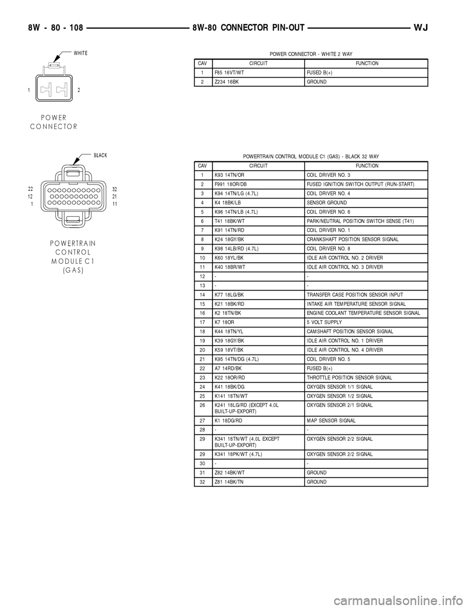
POWER CONNECTOR - WHITE 2 WAY
CAV CIRCUIT FUNCTION
1 F85 16VT/WT FUSED B(+)
2 Z234 16BK GROUND
POWERTRAIN CONTROL MODULE C1 (GAS) - BLACK 32 WAY
CAV CIRCUIT FUNCTION
1 K93 14TN/OR COIL DRIVER NO. 3
2 F991 18OR/DB FUSED IGNITION SWITCH OUTPUT (RUN-START)
3 K94 14TN/LG (4.7L) COIL DRIVER NO. 4
4 K4 18BK/LB SENSOR GROUND
5 K96 14TN/LB (4.7L) COIL DRIVER NO. 6
6 T41 18BK/WT PARK/NEUTRAL POSITION SWITCH SENSE (T41)
7 K91 14TN/RD COIL DRIVER NO. 1
8 K24 18GY/BK CRANKSHAFT POSITION SENSOR SIGNAL
9 K98 14LB/RD (4.7L) COIL DRIVER NO. 8
10 K60 18YL/BK IDLE AIR CONTROL NO. 2 DRIVER
11 K40 18BR/WT IDLE AIR CONTROL NO. 3 DRIVER
12 - -
13 - -
14 K77 18LG/BK TRANSFER CASE POSITION SENSOR INPUT
15 K21 18BK/RD INTAKE AIR TEMPERATURE SENSOR SIGNAL
16 K2 18TN/BK ENGINE COOLANT TEMPERATURE SENSOR SIGNAL
17 K7 18OR 5 VOLT SUPPLY
18 K44 18TN/YL CAMSHAFT POSITION SENSOR SIGNAL
19 K39 18GY/BK IDLE AIR CONTROL NO. 1 DRIVER
20 K59 18VT/BK IDLE AIR CONTROL NO. 4 DRIVER
21 K95 14TN/DG (4.7L) COIL DRIVER NO. 5
22 A7 14RD/BK FUSED B(+)
23 K22 18OR/RD THROTTLE POSITION SENSOR SIGNAL
24 K41 18BK/DG OXYGEN SENSOR 1/1 SIGNAL
25 K141 18TN/WT OXYGEN SENSOR 1/2 SIGNAL
26 K241 18LG/RD (EXCEPT 4.0L
BUILT-UP-EXPORT)OXYGEN SENSOR 2/1 SIGNAL
27 K1 18DG/RD MAP SENSOR SIGNAL
28 - -
29 K341 18TN/WT (4.0L EXCEPT
BUILT-UP-EXPORT)OXYGEN SENSOR 2/2 SIGNAL
29 K341 18PK/WT (4.7L) OXYGEN SENSOR 2/2 SIGNAL
30 - -
31 Z82 14BK/WT GROUND
32 Z81 14BK/TN GROUND
8W - 80 - 108 8W-80 CONNECTOR PIN-OUTWJ
Page 1177 of 2199
CONNECTOR NAME/
NUMBERCOLOR LOCATION FIG.
Blower Motor Controller (AZC) BK Behind Right Hand Side of
Instrument PanelN/S
Blower Motor Resistor Block
(MTC)BK Behind Right Hand Side of
Instrument PanelN/S
Body Control Module - C1 GY Lower Left Side of Instrument Panel 21, 22
Body Control Module-C2 -LHD WT Lower Left Side of Instrument Panel 21
Body Control Module-C2 -
RHDGY Lower Left Side of Instrument Panel 22
Boost Pressure Sensor
(Diesel)BK Top Front of Engine N/S
Brake Lamp Switch GY Brake Pedal Arm 31
C100 BK Right Front Engine Compartment 2, 5
C101 (4.0L RHD) LTGY Rear of Engine Compartment 15
C101 (4.7L RHD) BK Rear of Engine Compartment N/S
C102 (Diesel) BK Left Rear Engine Compartment 4, 7
C102 (Gas) BK Right Rear Engine Compartment 5, 10, 11, 14, 15, 18
C103 (Diesel) LTGY Rear of Engine 4, 7
C103 (Gas) GY Right Rear Engine Compartment 5, 10 11, 14, 15
C104 LTGY Right Rear Engine Compartment 14 18
C105 (Diesel) GY Right Rear Engine Compartment 4, 7, 8
C106 (Diesel) GY Lower Right Instrument Panel N/S
C106 (Gas RHD) GY Lower Right Instrument Panel N/S
C107 (Diesel) GY Left Rear Engine Compartment 4
C107 (LHD) BK Passenger Side Near Kick Panel 3, 30, 35
C107 (RHD) GY Passenger Side Near Kick Panel 3, 31
C108 BK Left Cowl 3, 4
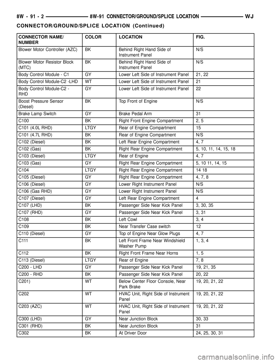
C109 BK Near Transfer Case switch 12
C110 (Diesel) GY Top of Engine Near Glow Plugs 4, 7
C111 BK Left Front Frame Near Windshield
Washer Pump1, 3, 4
C112 BK Right Front Frame Near Horns 1, 5
C113 (Diesel) LTGY Rear of Engine 7, 8
C200 - LHD GY Passenger Side Near Kick Panel 19, 21, 35
C200 - RHD BK Passenger Side Near Kick Panel 20, 22
C201) WT Below Center Floor Console, Near
Park Brake19, 20, 21, 22
C202 WT HVAC Unit, Right Side of Instrument
Panel19, 20, 21, 22
C203 (AZC) WT HVAC Unit, Right Side of Instrument
Panel19, 20, 21, 22
C300 (LHD) GY Near Junction Block 30, 33
C301 (RHD) BK Near Junction Block 31
C302 BK At Driver Door 24, 25, 30, 31
8W - 91 - 2 8W-91 CONNECTOR/GROUND/SPLICE LOCATIONWJ
CONNECTOR/GROUND/SPLICE LOCATION (Continued)
Page 1186 of 2199
CONNECTOR NAME/
NUMBERCOLOR LOCATION FIG.
Trailer Tow Brake Lamp Relay BK Left Quarter Panel N/S
Trailer Tow Circuit Breaker BK Left Quarter Panel N/S
Trailer Tow Connector BK In Rear Bumper 39
Trailer Tow Left Turn Relay BK Left Quarter Panel N/S
Trailer Tow Right Turn Relay BK Left Quarter Panel N/S
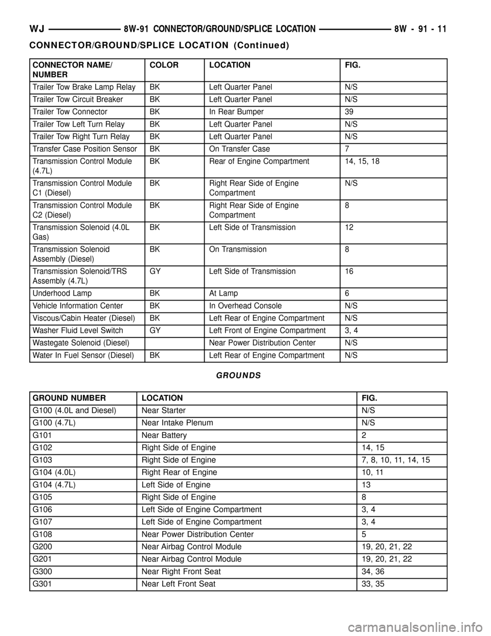
Transfer Case Position Sensor BK On Transfer Case 7
Transmission Control Module
(4.7L)BK Rear of Engine Compartment 14, 15, 18
Transmission Control Module
C1 (Diesel)BK Right Rear Side of Engine
CompartmentN/S
Transmission Control Module
C2 (Diesel)BK Right Rear Side of Engine
Compartment8
Transmission Solenoid (4.0L
Gas)BK Left Side of Transmission 12
Transmission Solenoid
Assembly (Diesel)BK On Transmission 8
Transmission Solenoid/TRS
Assembly (4.7L)GY Left Side of Transmission 16
Underhood Lamp BK At Lamp 6
Vehicle Information Center BK In Overhead Console N/S
Viscous/Cabin Heater (Diesel) BK Left Rear of Engine Compartment N/S
Washer Fluid Level Switch GY Left Front of Engine Compartment 3, 4
Wastegate Solenoid (Diesel) Near Power Distribution Center N/S
Water In Fuel Sensor (Diesel) BK Left Rear of Engine Compartment N/S
GROUNDS
GROUND NUMBER LOCATION FIG.
G100 (4.0L and Diesel) Near Starter N/S
G100 (4.7L) Near Intake Plenum N/S
G101 Near Battery 2
G102 Right Side of Engine 14, 15
G103 Right Side of Engine 7, 8, 10, 11, 14, 15
G104 (4.0L) Right Rear of Engine 10, 11
G104 (4.7L) Left Side of Engine 13
G105 Right Side of Engine 8
G106 Left Side of Engine Compartment 3, 4
G107 Left Side of Engine Compartment 3, 4
G108 Near Power Distribution Center 5
G200 Near Airbag Control Module 19, 20, 21, 22
G201 Near Airbag Control Module 19, 20, 21, 22
G300 Near Right Front Seat 34, 36
G301 Near Left Front Seat 33, 35
WJ8W-91 CONNECTOR/GROUND/SPLICE LOCATION 8W - 91 - 11
CONNECTOR/GROUND/SPLICE LOCATION (Continued)
Page 1546 of 2199

REMOVAL
The overdrive unit can be removed and serviced
separately. It is not necessary to remove the entire
transmission assembly to perform overdrive unit
repairs.
If only the overdrive unit requires service, refer to
Overdrive Removal for proper procedures.
CAUTION: The transmission and torque converter
must be removed as an assembly to avoid compo-
nent damage. The converter driveplate, pump bush-
ing, or oil seal can be damaged if the converter is
left attached to the driveplate during removal. Be
sure to remove the transmission and converter as
an assembly.
(1) Disconnect battery negative cable.
(2) Disconnect and lower or remove necessary
exhaust components.
(3) Disconnect fluid cooler lines at transmission.
(4) Remove starter motor. (Refer to 8 - ELECTRI-
CAL/STARTING/STARTER MOTOR - REMOVAL)
(5) Disconnect and remove crankshaft position sen-
sor. (Refer to 14 - FUEL SYSTEM/FUEL INJEC-
TION/CRANKSHAFT POSITION SENSOR -
REMOVAL) Retain sensor attaching bolts.
CAUTION: The crankshaft position sensor will be
damaged if the transmission is removed, or
installed, while the sensor is still bolted to the
engine block, or transmission (4.0L only). To avoid
damage, be sure to remove the sensor before
removing the transmission.
(6) Remove the bolts holding the bell housing
brace to the transmission.
(7) Remove nut holding the bell housing brace to
the engine to transmission bending brace.
(8) Remove the bell housing brace from the trans-
mission (Fig. 13).
(9) Remove the bolt holding the torque converter
cover to the transmission.
(10) Remove the torque converter cover from the
transmission.
(11) If transmission is being removed for overhaul,
remove transmission oil pan, drain fluid and reinstall
pan.
(12) Remove fill tube bracket bolts and pull tube
out of transmission. Retain fill tube seal. On4x4
models, it will also be necessary to remove bolt
attaching transfer case vent tube to converter hous-
ing.
(13) Rotate crankshaft in clockwise direction until
converter bolts are accessible. Then remove bolts one
at a time. Rotate crankshaft with socket wrench on
dampener bolt.(14) Mark propeller shaft and axle yokes for
assembly alignment. Then disconnect and remove
propeller shaft. On4x4models, remove both propel-
ler shafts.
(15) Disconnect wires from park/neutral position
switch and transmission solenoid.
(16) Disconnect gearshift cable from transmission
manual valve lever (Fig. 14).
Fig. 13 Bell Housing Brace and Converter Cover
1 - Transmission
2 - Torque Converter Cover
3 - Bellhousing Brace
Fig. 14 Transmission Shift Cable
1 - SHIFT CABLE
2 - MANUAL LEVER
3 - MANUAL LEVER
WJAUTOMATIC TRANSMISSION - 42RE 21 - 27
AUTOMATIC TRANSMISSION - 42RE (Continued)
Page 1548 of 2199
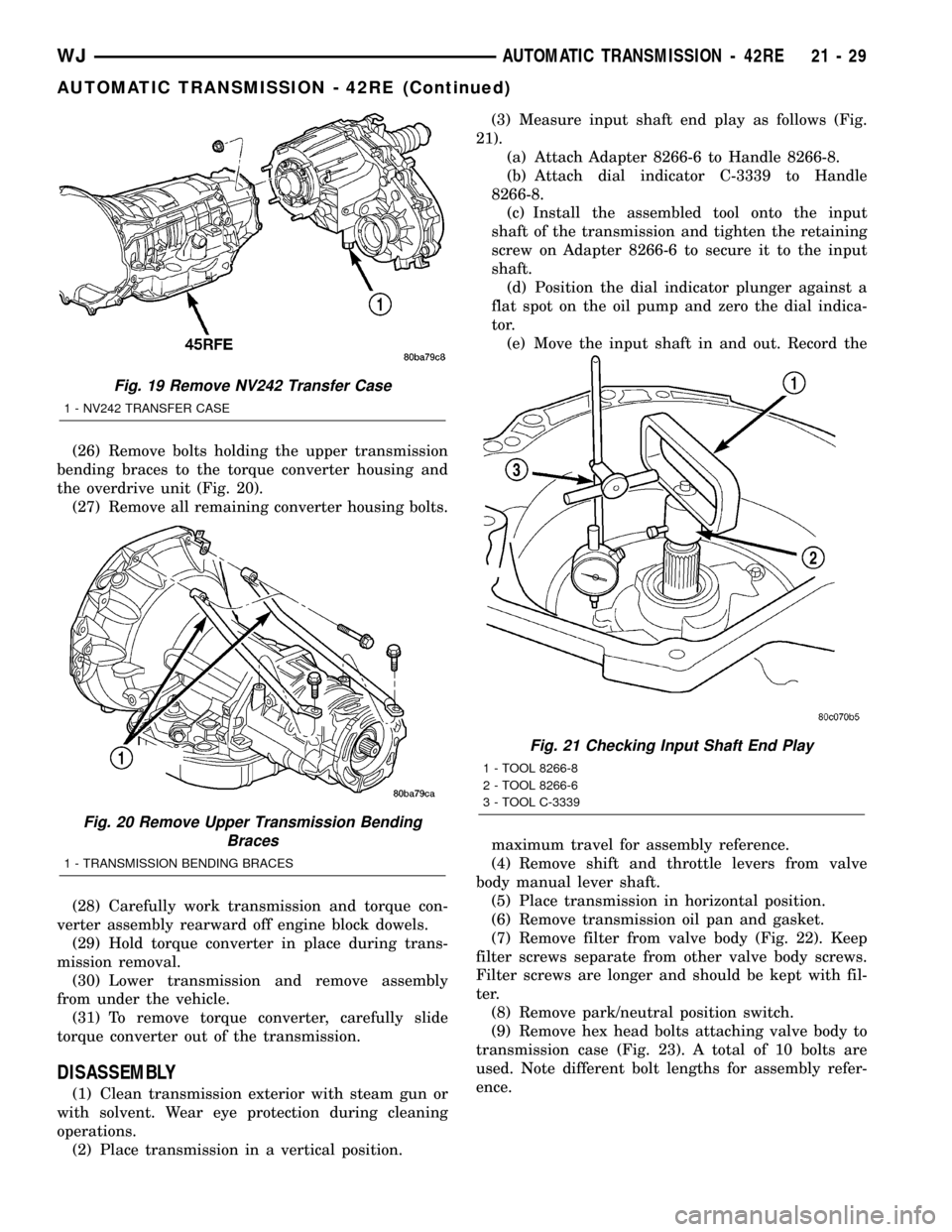
(26) Remove bolts holding the upper transmission
bending braces to the torque converter housing and
the overdrive unit (Fig. 20).
(27) Remove all remaining converter housing bolts.
(28) Carefully work transmission and torque con-
verter assembly rearward off engine block dowels.
(29) Hold torque converter in place during trans-
mission removal.
(30) Lower transmission and remove assembly
from under the vehicle.
(31) To remove torque converter, carefully slide
torque converter out of the transmission.
DISASSEMBLY
(1) Clean transmission exterior with steam gun or
with solvent. Wear eye protection during cleaning
operations.
(2) Place transmission in a vertical position.(3) Measure input shaft end play as follows (Fig.
21).
(a) Attach Adapter 8266-6 to Handle 8266-8.
(b) Attach dial indicator C-3339 to Handle
8266-8.
(c) Install the assembled tool onto the input
shaft of the transmission and tighten the retaining
screw on Adapter 8266-6 to secure it to the input
shaft.
(d) Position the dial indicator plunger against a
flat spot on the oil pump and zero the dial indica-
tor.
(e) Move the input shaft in and out. Record the
maximum travel for assembly reference.
(4) Remove shift and throttle levers from valve
body manual lever shaft.
(5) Place transmission in horizontal position.
(6) Remove transmission oil pan and gasket.
(7) Remove filter from valve body (Fig. 22). Keep
filter screws separate from other valve body screws.
Filter screws are longer and should be kept with fil-
ter.
(8) Remove park/neutral position switch.
(9) Remove hex head bolts attaching valve body to
transmission case (Fig. 23). A total of 10 bolts are
used. Note different bolt lengths for assembly refer-
ence.
Fig. 19 Remove NV242 Transfer Case
1 - NV242 TRANSFER CASE
Fig. 20 Remove Upper Transmission Bending
Braces
1 - TRANSMISSION BENDING BRACES
Fig. 21 Checking Input Shaft End Play
1 - TOOL 8266-8
2 - TOOL 8266-6
3 - TOOL C-3339
WJAUTOMATIC TRANSMISSION - 42RE 21 - 29
AUTOMATIC TRANSMISSION - 42RE (Continued)
Page 1561 of 2199

(11) Move transmission forward. Then raise, lower
or tilt transmission to align converter housing with
engine block dowels.
(12) Carefully work transmission forward and over
engine block dowels until converter hub is seated in
crankshaft.
(13) Install two bolts to attach converter housing
to engine.
(14) Install the upper transmission bending braces
to the torque converter housing and the overdrive
unit. Tighten the bolts to 41 N´m (30 ft.lbs.).
(15) Install remaining torque converter housing to
engine bolts. Tighten to 68 N´m (50 ft.lbs.).
(16) Install rear transmission crossmember.
Tighten crossmember to frame bolts to 68 N´m (50
ft.lbs.).
(17) Install rear support to transmission. Tighten
bolts to 47 N´m (35 ft.lbs.).
(18) Lower transmission onto crossmember and
install bolts attaching transmission mount to cross-
member. Tighten clevis bracket to crossmember bolts
to 47 N´m (35 ft.lbs.). Tighten the clevis bracket to
rear support bolt to 68 N´m (50 ft.lbs.).
(19) Remove engine support fixture.
(20) Install crankshaft position sensor. (Refer to 14
- FUEL SYSTEM/FUEL INJECTION/CRANKSHAFT
POSITION SENSOR - INSTALLATION)
(21) Install new plastic retainer grommet on any
shift cable that was disconnected. Grommets should
not be reused. Use pry tool to remove rod from grom-
met and cut away old grommet. Use pliers to snap
new grommet into cable and to snap grommet onto
lever.
(22) Connect gearshift and throttle valve cable to
transmission.
(23) Connect wires to park/neutral position switch
and transmission solenoid connector. Be sure trans-
mission harnesses are properly routed.CAUTION: It is essential that correct length bolts be
used to attach the converter to the driveplate. Bolts
that are too long will damage the clutch surface
inside the converter.
(24) Install all torque converter-to-driveplate bolts
by hand.
(25) Verify that the torque converter is pulled
flush to the driveplate. Tighten bolts to 31 N´m (270
in. lbs.).
(26) Install converter housing access cover. Tighten
bolt to 23 N´m (200 in.lbs.).
(27) Install the bell housing brace to the torque
converter cover and the engine to transmission bend-
ing brace. Tighten the bolts and nut to 41 N´m (30
ft.lbs.).
(28) Install starter motor (Refer to 8 - ELECTRI-
CAL/STARTING/STARTER MOTOR - INSTALLA-
TION) and cooler line bracket.
(29) Connect cooler lines to transmission.
(30) Install transmission fill tube. Install new seal
on tube before installation.
(31) Install exhaust components.
(32) Install transfer case. Tighten transfer case
nuts to 35 N´m (26 ft.lbs.).
(33) Install the transfer case shift cable to the
cable support bracket and the transfer case shift
lever.
(34) Align and connect propeller shaft(s).
(35) Adjust gearshift linkage and throttle valve
cable if necessary.
(36) Lower vehicle.
(37) Fill transmission with MopartATF +4, type
9602, fluid.
21 - 42 AUTOMATIC TRANSMISSION - 42REWJ
AUTOMATIC TRANSMISSION - 42RE (Continued)
Page 1575 of 2199
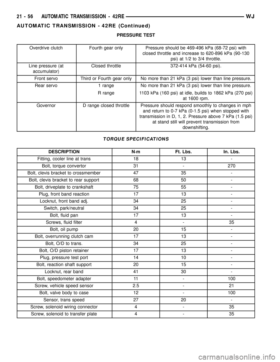
PRESSURE TEST
Overdrive clutch Fourth gear only Pressure should be 469-496 kPa (68-72 psi) with
closed throttle and increase to 620-896 kPa (90-130
psi) at 1/2 to 3/4 throttle.
Line pressure (at
accumulator)Closed throttle 372-414 kPa (54-60 psi).
Front servo Third or Fourth gear only No more than 21 kPa (3 psi) lower than line pressure.
Rear servo 1 range No more than 21 kPa (3 psi) lower than line pressure.
R range 1103 kPa (160 psi) at idle, builds to 1862 kPa (270 psi)
at 1600 rpm.
Governor D range closed throttle Pressure should respond smoothly to changes in mph
and return to 0-7 kPa (0-1.5 psi) when stopped with
transmission in D, 1, 2. Pressure above 7 kPa (1.5 psi)
at stand still will prevent transmission from
downshifting.
TORQUE SPECIFICATIONS
DESCRIPTION N´m Ft. Lbs. In. Lbs.
Fitting, cooler line at trans 18 13 -
Bolt, torque convertor 31 - 270
Bolt, clevis bracket to crossmember 47 35 -
Bolt, clevis bracket to rear support 68 50 -
Bolt, driveplate to crankshaft 75 55 -
Plug, front band reaction 17 13 -
Locknut, front band adj. 34 25 -
Switch, park/neutral 34 25 -
Bolt, fluid pan 17 13 -
Screws, fluid filter 4 - 35
Bolt, oil pump 20 15 -
Bolt, overrunning clutch cam 17 13 -
Bolt, O/D to trans. 34 25 -
Bolt, O/D piston retainer 17 13 -
Plug, pressure test port 14 10 -
Bolt, reaction shaft support 20 15 -
Locknut, rear band 41 30 -
Bolt, speedometer adapter 11 - 100
Screw, vehicle speed sensor 2.5 - 21
Bolt, valve body to case 12 - 100
Sensor, trans speed 27 20 -
Screw, solenoid wiring connector 4 - 35
Screw, solenoid to transfer plate 4 - 35
21 - 56 AUTOMATIC TRANSMISSION - 42REWJ
AUTOMATIC TRANSMISSION - 42RE (Continued)
Page 1599 of 2199

INCORRECT if the engine starts in one but not both
positions. If the engine starts in any position other
than PARK or NEUTRAL, or if the engine will not
start at all, the park/neutral position switch or TRS
may be faulty.
(1) Shift transmission into PARK.
(2) Remove floor console as necessary for access to
the shift cable adjustment. (Refer to 23 - BODY/IN-
TERIOR/FLOOR CONSOLE - REMOVAL)
(3) Loosen the shift cable adjustment screw (Fig.
106).
(4) Raise vehicle.
(5) Unsnap cable eyelet from transmission shift
lever (Fig. 107).
(6) Verify transmission shift lever is in PARK
detent by moving lever fully rearward. Last rearward
detent is PARK position.
(7) Verify positive engagement of transmission
park lock by attempting to rotate propeller shaft.
Shaft will not rotate when park lock is engaged.
(8) Snap cable eyelet onto transmission shift lever.
(9) Lower vehicle
(10) Tighten the shift cable adjustment screw to 7
N´m (65 in.lbs.).
(11) Verify correct operation.
(12) Install any floor console components removed
for access. (Refer to 23 - BODY/INTERIOR/FLOOR
CONSOLE - INSTALLATION)
OIL PUMP
DESCRIPTION
The oil pump (Fig. 108) is located in the pump
housing inside the bell housing of the transmission
case. The oil pump consists of an inner and outer
gear (Fig. 109), a housing, and a cover that also
serves as the reaction shaft support.
OPERATION
As the torque converter rotates, the converter hub
rotates the inner and outer gears. As the gears
rotate, the clearance between the gear teeth
increases in the crescent area, and creates a suction
at the inlet side of the pump. This suction draws
fluid through the pump inlet from the oil pan. As the
clearance between the gear teeth in the crescent area
decreases, it forces pressurized fluid into the pump
outlet and to the valve body.
Fig. 106 Shift Cable at the Shifter
1 - SHIFT LEVER PIN
2 - ADJUSTMENT SCREW
3 - SHIFT CABLE
4 - SHIFTER ASSEMBLY BRACKET
Fig. 107 Shift Cable at Transmission
1 - TRANSMISSION SHIFTER CABLE
2 - THROTTLE VALVE CABLE
3 - TRANSFER CASE SHIFTER CABLE
4 - TRANSFER CASE SHIFTER CABLE BRACKET RETAINING
BOLT(S)
5 - THROTTLE VALVE CABLE BRACKET RETAINING BOLT
6 - ELECTRICAL CONNECTORS
7 - TRANSMISSION FLUID LINES
21 - 80 AUTOMATIC TRANSMISSION - 42REWJ
GEARSHIFT CABLE (Continued)