2003 JEEP GRAND CHEROKEE Prime
[x] Cancel search: PrimePage 1739 of 2199
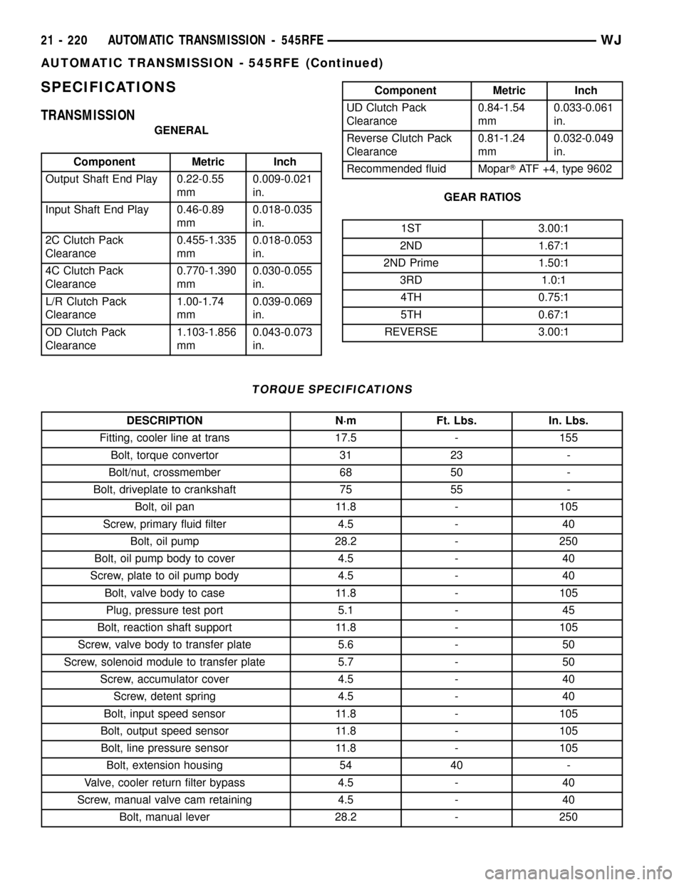
SPECIFICATIONS
TRANSMISSION
GENERAL
Component Metric Inch
Output Shaft End Play 0.22-0.55
mm0.009-0.021
in.
Input Shaft End Play 0.46-0.89
mm0.018-0.035
in.
2C Clutch Pack
Clearance0.455-1.335
mm0.018-0.053
in.
4C Clutch Pack
Clearance0.770-1.390
mm0.030-0.055
in.
L/R Clutch Pack
Clearance1.00-1.74
mm0.039-0.069
in.
OD Clutch Pack
Clearance1.103-1.856
mm0.043-0.073
in.
Component Metric Inch
UD Clutch Pack
Clearance0.84-1.54
mm0.033-0.061
in.
Reverse Clutch Pack
Clearance0.81-1.24
mm0.032-0.049
in.
Recommended fluid MoparTATF +4, type 9602
GEAR RATIOS
1ST 3.00:1
2ND 1.67:1
2ND Prime 1.50:1
3RD 1.0:1
4TH 0.75:1
5TH 0.67:1
REVERSE 3.00:1
TORQUE SPECIFICATIONS
DESCRIPTION N´m Ft. Lbs. In. Lbs.
Fitting, cooler line at trans 17.5 - 155
Bolt, torque convertor 31 23 -
Bolt/nut, crossmember 68 50 -
Bolt, driveplate to crankshaft 75 55 -
Bolt, oil pan 11.8 - 105
Screw, primary fluid filter 4.5 - 40
Bolt, oil pump 28.2 - 250
Bolt, oil pump body to cover 4.5 - 40
Screw, plate to oil pump body 4.5 - 40
Bolt, valve body to case 11.8 - 105
Plug, pressure test port 5.1 - 45
Bolt, reaction shaft support 11.8 - 105
Screw, valve body to transfer plate 5.6 - 50
Screw, solenoid module to transfer plate 5.7 - 50
Screw, accumulator cover 4.5 - 40
Screw, detent spring 4.5 - 40
Bolt, input speed sensor 11.8 - 105
Bolt, output speed sensor 11.8 - 105
Bolt, line pressure sensor 11.8 - 105
Bolt, extension housing 54 40 -
Valve, cooler return filter bypass 4.5 - 40
Screw, manual valve cam retaining 4.5 - 40
Bolt, manual lever 28.2 - 250
21 - 220 AUTOMATIC TRANSMISSION - 545RFEWJ
AUTOMATIC TRANSMISSION - 545RFE (Continued)
Page 1753 of 2199

OPERATION
2C CLUTCH
The 2C clutch is hydraulically applied in second
and fifth gear by pressurized fluid against the 2C
piston. When the 2C clutch is applied, the reverse
sun gear assembly is held or grounded to the trans-
mission case by holding the reaction planetary car-
rier.
4C CLUTCH
The 4C clutch is hydraulically applied in second
prime and fourth gear by pressurized fluid againstthe 4C clutch piston. When the 4C clutch is applied,
the reaction annulus gear is held or grounded to the
transmission case.
LOW/REVERSE CLUTCH
The Low/Reverse clutch is hydraulically applied in
park, reverse, neutral, and first gear, only at low
speeds, by pressurized fluid against the Low/Reverse
clutch piston. When the Low/Reverse clutch is
applied, the input annulus assembly is held or
grounded to the transmission case.
Fig. 67 Low/Reverse Clutch
1 - SNAP-RING (SELECT) 8 - SEAL
2 - REACTION PLATE 9 - BELLEVILLE SPRING
3 - DISC 10 - RETAINER
4 - PLATE 11 - SNAP-RING
5 - L/R CLUTCH RETAINER 12 - OVERRUNNING CLUTCH
6 - SEAL 13 - SNAP-RING
7 - PISTON
21 - 234 AUTOMATIC TRANSMISSION - 545RFEWJ
HOLDING CLUTCHES (Continued)
Page 1754 of 2199

INPUT CLUTCH ASSEMBLY
DESCRIPTION
Three hydraulically applied input clutches are used
to drive planetary components. The underdrive, over-
drive, and reverse clutches are considered input
clutches and are contained within the input clutch
assembly (Fig. 68) and (Fig. 69). The input clutch
assembly also contains:
²Input shaft
²Input hub
²Clutch retainer
²Underdrive piston²Overdrive/reverse piston
²Overdrive hub
²Underdrive hubOPERATION
The three input clutches are responsible for driving
different components of the planetary geartrain.
UNDERDRIVE CLUTCH
The underdrive clutch is hydraulically applied in
first, second, second prime, and third (direct) gears
by pressurized fluid against the underdrive piston.
Fig. 68 Input Clutch Assembly - Part 1
1 - INPUT CLUTCH HUB 11 - UD CLUTCH
2 - O-RING SEALS 12 - PLATE
3 - SEAL 13 - CLUTCH RETAINER
4 - SNAP-RING 14 - SEAL
5 - SNAP-RING 15 - OD/REV PISTON
6 - UD BALANCE PISTON 16 - BELLEVILLE SPRING
7 - SNAP-RING 17 - SNAP-RING
8 - UD PISTON 18 - SEAL RINGS
9 - SPRING 19 - INPUT SHAFT
10 - DISC 20 - LUBRICATION CHECK VALVE AND SNAP-RING
WJAUTOMATIC TRANSMISSION - 545RFE 21 - 235
Page 1790 of 2199
TRANSMISSION SOLENOID/
TRS ASSEMBLY
DESCRIPTION
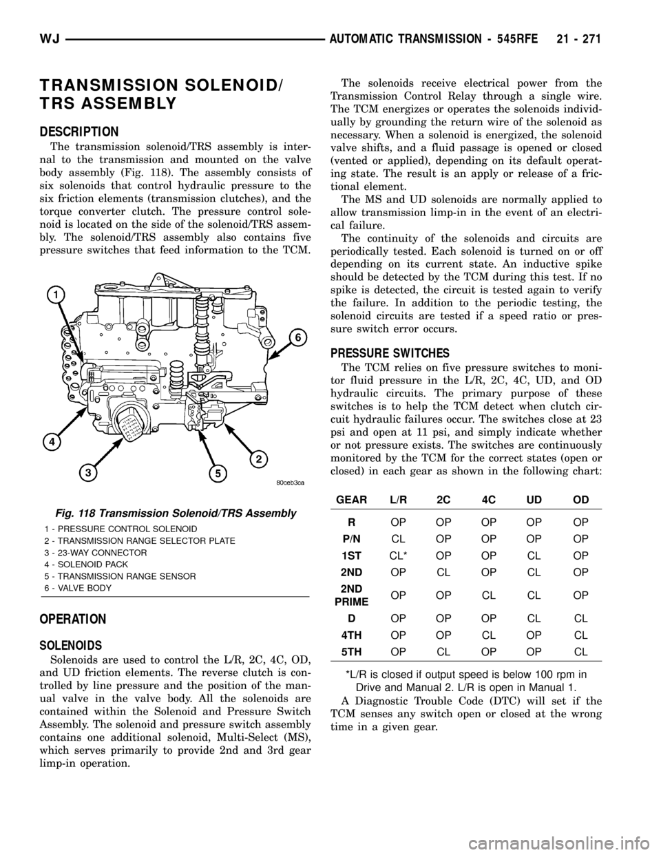
The transmission solenoid/TRS assembly is inter-
nal to the transmission and mounted on the valve
body assembly (Fig. 118). The assembly consists of
six solenoids that control hydraulic pressure to the
six friction elements (transmission clutches), and the
torque converter clutch. The pressure control sole-
noid is located on the side of the solenoid/TRS assem-
bly. The solenoid/TRS assembly also contains five
pressure switches that feed information to the TCM.
OPERATION
SOLENOIDS
Solenoids are used to control the L/R, 2C, 4C, OD,
and UD friction elements. The reverse clutch is con-
trolled by line pressure and the position of the man-
ual valve in the valve body. All the solenoids are
contained within the Solenoid and Pressure Switch
Assembly. The solenoid and pressure switch assembly
contains one additional solenoid, Multi-Select (MS),
which serves primarily to provide 2nd and 3rd gear
limp-in operation.The solenoids receive electrical power from the
Transmission Control Relay through a single wire.
The TCM energizes or operates the solenoids individ-
ually by grounding the return wire of the solenoid as
necessary. When a solenoid is energized, the solenoid
valve shifts, and a fluid passage is opened or closed
(vented or applied), depending on its default operat-
ing state. The result is an apply or release of a fric-
tional element.
The MS and UD solenoids are normally applied to
allow transmission limp-in in the event of an electri-
cal failure.
The continuity of the solenoids and circuits are
periodically tested. Each solenoid is turned on or off
depending on its current state. An inductive spike
should be detected by the TCM during this test. If no
spike is detected, the circuit is tested again to verify
the failure. In addition to the periodic testing, the
solenoid circuits are tested if a speed ratio or pres-
sure switch error occurs.
PRESSURE SWITCHES
The TCM relies on five pressure switches to moni-
tor fluid pressure in the L/R, 2C, 4C, UD, and OD
hydraulic circuits. The primary purpose of these
switches is to help the TCM detect when clutch cir-
cuit hydraulic failures occur. The switches close at 23
psi and open at 11 psi, and simply indicate whether
or not pressure exists. The switches are continuously
monitored by the TCM for the correct states (open or
closed) in each gear as shown in the following chart:
GEAR L/R 2C 4C UD OD
ROP OP OP OP OP
P/NCL OP OP OP OP
1STCL* OP OP CL OP
2NDOP CL OP CL OP
2ND
PRIMEOP OP CL CL OP
DOP OP OP CL CL
4THOP OP CL OP CL
5THOP CL OP OP CL
*L/R is closed if output speed is below 100 rpm in
Drive and Manual 2. L/R is open in Manual 1.
A Diagnostic Trouble Code (DTC) will set if the
TCM senses any switch open or closed at the wrong
time in a given gear.
Fig. 118 Transmission Solenoid/TRS Assembly
1 - PRESSURE CONTROL SOLENOID
2 - TRANSMISSION RANGE SELECTOR PLATE
3 - 23-WAY CONNECTOR
4 - SOLENOID PACK
5 - TRANSMISSION RANGE SENSOR
6 - VALVE BODY
WJAUTOMATIC TRANSMISSION - 545RFE 21 - 271
Page 1955 of 2199

PAINT TOUCH-UP
DESCRIPTION
When a painted metal surface has been scratched
or chipped, it should be touched-up as soon as possi-
ble to avoid corrosion. For best results, use Mopart
Scratch Filler/Primer, Touch-Up Paints and Clear Top
Coat. Refer to Introduction group of this manual for
Body Code Plate information.
WARNING: USE AN OSHA APPROVED BREATHING
FILTER WHEN SPRAYING PAINT OR SOLVENTS IN
A CONFINED AREA. PERSONAL INJURY CAN
RESULT.
OPERATION
(1) Scrape loose paint and corrosion from inside
scratch or chip.
(2) Clean affected area with MopartTar/Road Oil
Remover, and allow to dry.
(3) Fill the inside of the scratch or chip with a coat
of filler/primer. Do not overlap primer onto good sur-
face finish. The applicator brush should be wet
enough to puddle-fill the defect without running. Do
not stroke brush applicator on body surface. Allow
the filler/primer to dry hard.
(4) Cover the filler/primer with color touch-up
paint. Do not overlap touch-up color onto the original
color coat around the scratch or chip. Butt the new
color to the original color, if possible. Do not stroke
applicator brush on body surface. Allow touch-up
paint to dry hard.
(5) On vehicles without clear coat, the touch-up
color can be lightly finesse sanded (1500 grit) and
polished with rubbing compound.
(6) On vehicles with clear coat, apply clear top coat
to touch-up paint with the same technique as
described in Step 4. Allow clear top coat to dry hard.
If desired, Step 5 can be performed on clear top coat.
WARNING: AVOID PROLONGED SKIN CONTACT
WITH PETROLEUM OR ALCOHOL ± BASED CLEAN-
ING SOLVENTS. PERSONAL INJURY CAN RESULT.
AVOID PROLONGED SKIN CONTACT WITH PETRO-
LEUM OR ALCOHOL ± BASED CLEANING SOL-
VENTS. PERSONAL INJURY CAN RESULT.
FINESSE SANDING/BUFFING &
POLISHING
DESCRIPTION
CAUTION: Do not remove more than .5 mils of
clearcoat finish, if equipped. Base coat paint must
retain clear coat for durability.
Use a Paint Thickness Gauge #PR-ETG-2X or equiv-
alent to determine film thickness before and after
the repair.
Minor acid etching, orange peel, or smudging in
clearcoat or single-stage finishes can be reduced with
light finesse sanding, hand buffing, and polishing.If
the finish has been finesse sanded in the past,
it cannot be repeated. Finesse sanding opera-
tion should be performed by a trained automo-
tive paint technician.
23 - 82 PAINTWJ
Page 1966 of 2199
STATIONARY GLASS
TABLE OF CONTENTS
page page
DOOR GLASS
REMOVAL.............................93
INSTALLATION.........................93
QUARTER WINDOW
REMOVAL.............................93INSTALLATION.........................93
WINDSHIELD
REMOVAL.............................94
INSTALLATION.........................95
DOOR GLASS
REMOVAL
(1) Remove door trim panel.
(2) Remove waterdam.
(3) Remove inner belt weatherstrip.
(4) Remove bolt attaching bottom of rear glass run
channel to door.
(5) Pull run channel downward and separate from
door.
(6) Remove screws attaching stationary door glass
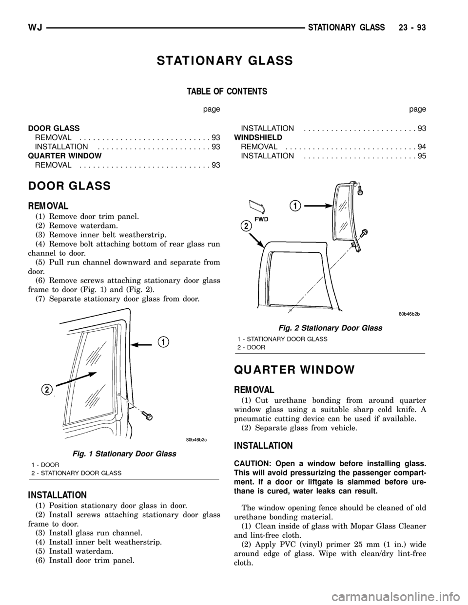
frame to door (Fig. 1) and (Fig. 2).
(7) Separate stationary door glass from door.
INSTALLATION
(1) Position stationary door glass in door.
(2) Install screws attaching stationary door glass
frame to door.
(3) Install glass run channel.
(4) Install inner belt weatherstrip.
(5) Install waterdam.
(6) Install door trim panel.
QUARTER WINDOW
REMOVAL
(1) Cut urethane bonding from around quarter
window glass using a suitable sharp cold knife. A
pneumatic cutting device can be used if available.
(2) Separate glass from vehicle.
INSTALLATION
CAUTION: Open a window before installing glass.
This will avoid pressurizing the passenger compart-
ment. If a door or liftgate is slammed before ure-
thane is cured, water leaks can result.
The window opening fence should be cleaned of old
urethane bonding material.
(1) Clean inside of glass with Mopar Glass Cleaner
and lint-free cloth.
(2) Apply PVC (vinyl) primer 25 mm (1 in.) wide
around edge of glass. Wipe with clean/dry lint-free
cloth.
Fig. 1 Stationary Door Glass
1 - DOOR
2 - STATIONARY DOOR GLASS
Fig. 2 Stationary Door Glass
1 - STATIONARY DOOR GLASS
2 - DOOR
WJSTATIONARY GLASS 23 - 93
Page 1967 of 2199
(3) Apply fence primer around edge of fence. Allow
at least eighteen minutes drying time.
(4) Apply a 10 mm (0.4 in.) bead of urethane
around window vinyl border location.
(5)
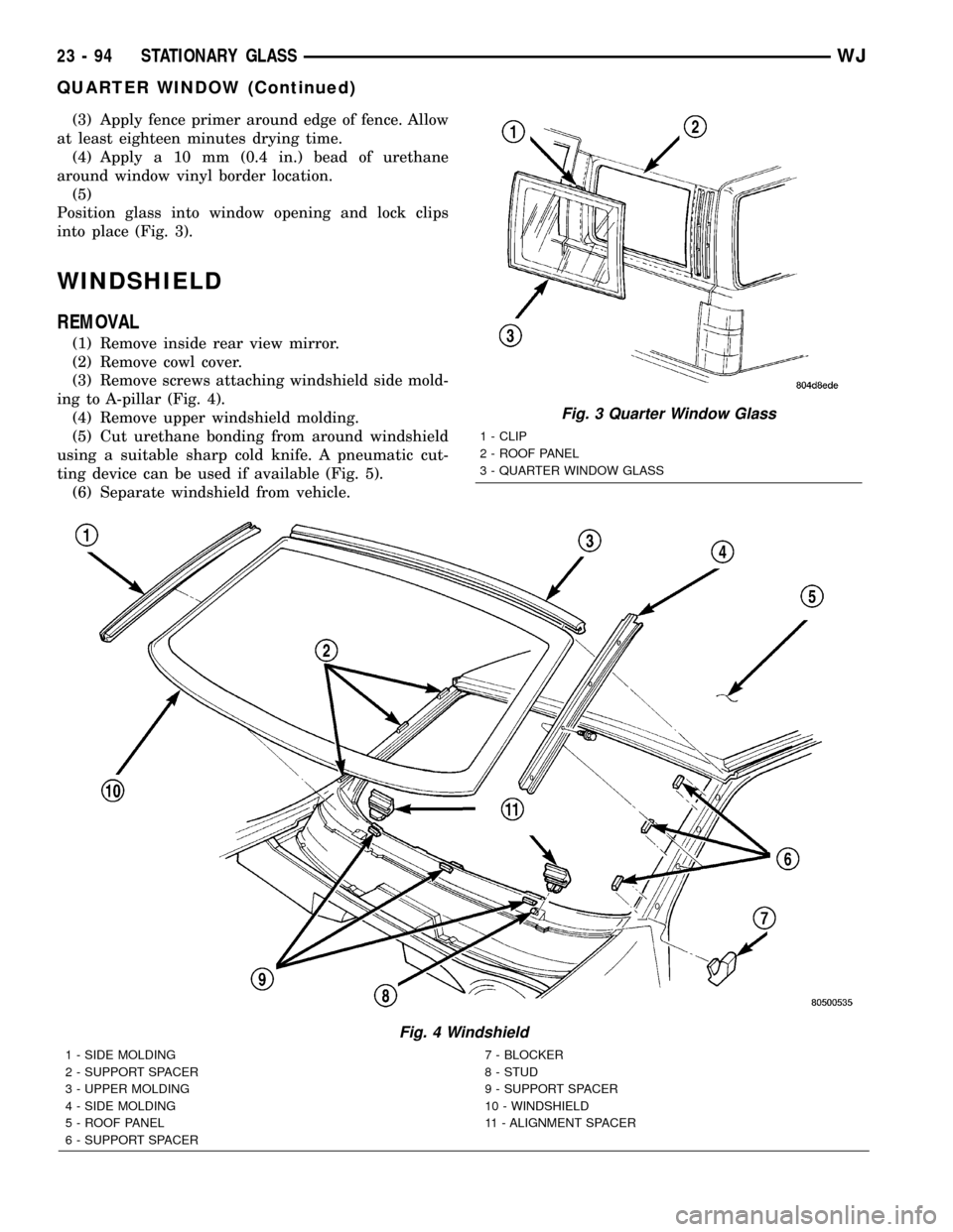
Position glass into window opening and lock clips
into place (Fig. 3).
WINDSHIELD
REMOVAL
(1) Remove inside rear view mirror.
(2) Remove cowl cover.
(3) Remove screws attaching windshield side mold-
ing to A-pillar (Fig. 4).
(4) Remove upper windshield molding.
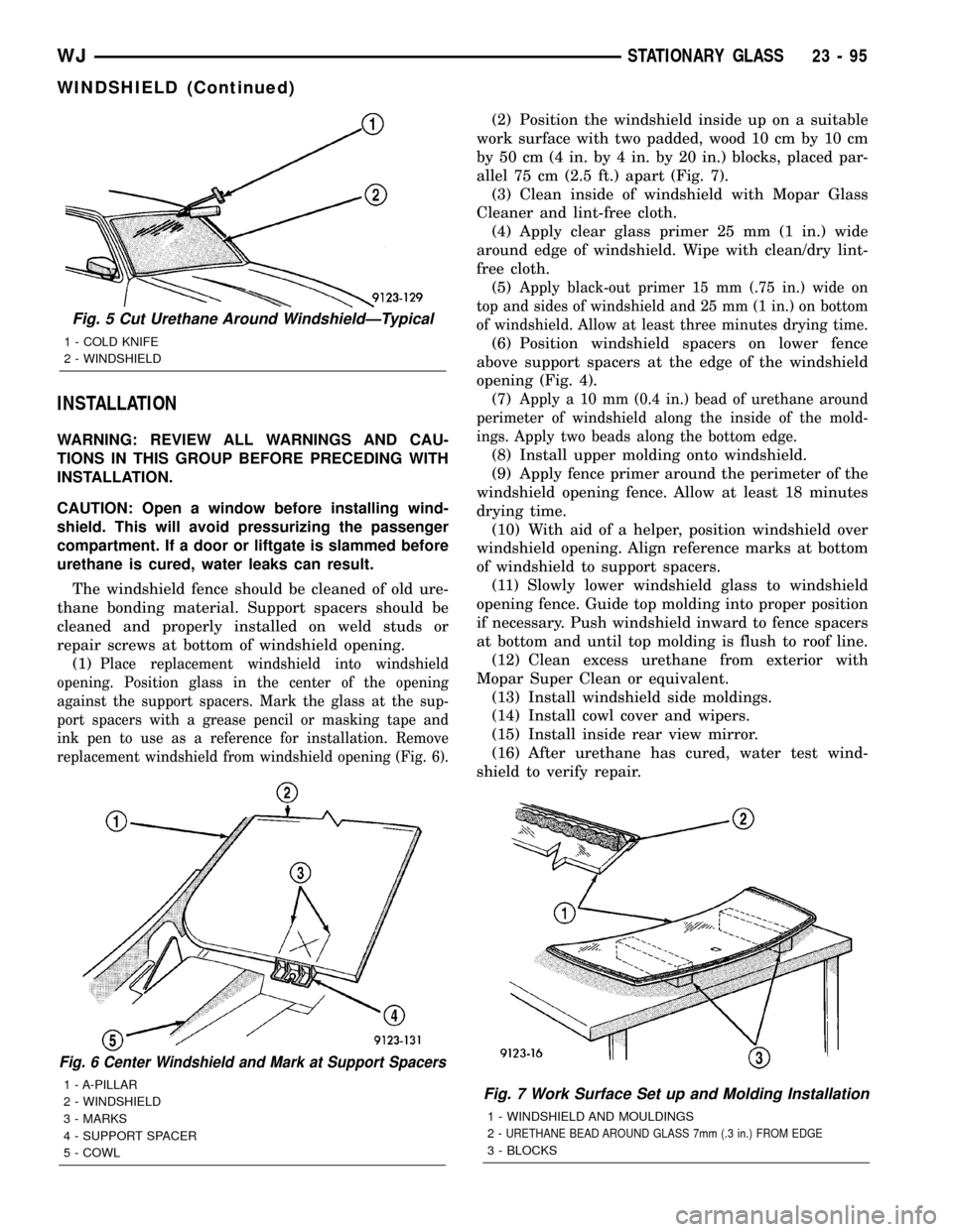
(5) Cut urethane bonding from around windshield
using a suitable sharp cold knife. A pneumatic cut-
ting device can be used if available (Fig. 5).
(6) Separate windshield from vehicle.
Fig. 3 Quarter Window Glass
1 - CLIP
2 - ROOF PANEL
3 - QUARTER WINDOW GLASS
Fig. 4 Windshield
1 - SIDE MOLDING
2 - SUPPORT SPACER
3 - UPPER MOLDING
4 - SIDE MOLDING
5 - ROOF PANEL
6 - SUPPORT SPACER7 - BLOCKER
8 - STUD
9 - SUPPORT SPACER
10 - WINDSHIELD
11 - ALIGNMENT SPACER
23 - 94 STATIONARY GLASSWJ
QUARTER WINDOW (Continued)
Page 1968 of 2199
INSTALLATION
WARNING: REVIEW ALL WARNINGS AND CAU-
TIONS IN THIS GROUP BEFORE PRECEDING WITH
INSTALLATION.
CAUTION: Open a window before installing wind-
shield. This will avoid pressurizing the passenger
compartment. If a door or liftgate is slammed before
urethane is cured, water leaks can result.
The windshield fence should be cleaned of old ure-
thane bonding material. Support spacers should be
cleaned and properly installed on weld studs or
repair screws at bottom of windshield opening.
(1)
Place replacement windshield into windshield
opening. Position glass in the center of the opening
against the support spacers. Mark the glass at the sup-
port spacers with a grease pencil or masking tape and
ink pen to use as a reference for installation. Remove
replacement windshield from windshield opening (Fig. 6).
(2) Position the windshield inside up on a suitable
work surface with two padded, wood 10 cm by 10 cm
by 50 cm (4 in. by 4 in. by 20 in.) blocks, placed par-
allel 75 cm (2.5 ft.) apart (Fig. 7).
(3) Clean inside of windshield with Mopar Glass
Cleaner and lint-free cloth.
(4) Apply clear glass primer 25 mm (1 in.) wide
around edge of windshield. Wipe with clean/dry lint-
free cloth.
(5)
Apply black-out primer 15 mm (.75 in.) wide on
top and sides of windshield and 25 mm (1 in.) on bottom
of windshield. Allow at least three minutes drying time.
(6) Position windshield spacers on lower fence
above support spacers at the edge of the windshield
opening (Fig. 4).
(7)
Apply a 10 mm (0.4 in.) bead of urethane around
perimeter of windshield along the inside of the mold-
ings. Apply two beads along the bottom edge.
(8) Install upper molding onto windshield.
(9) Apply fence primer around the perimeter of the
windshield opening fence. Allow at least 18 minutes
drying time.
(10) With aid of a helper, position windshield over
windshield opening. Align reference marks at bottom
of windshield to support spacers.
(11) Slowly lower windshield glass to windshield
opening fence. Guide top molding into proper position
if necessary. Push windshield inward to fence spacers
at bottom and until top molding is flush to roof line.
(12) Clean excess urethane from exterior with
Mopar Super Clean or equivalent.
(13) Install windshield side moldings.
(14) Install cowl cover and wipers.
(15) Install inside rear view mirror.
(16) After urethane has cured, water test wind-
shield to verify repair.
Fig. 6 Center Windshield and Mark at Support Spacers
1 - A-PILLAR
2 - WINDSHIELD
3 - MARKS
4 - SUPPORT SPACER
5 - COWLFig. 7 Work Surface Set up and Molding Installation
1 - WINDSHIELD AND MOULDINGS
2-
URETHANE BEAD AROUND GLASS 7mm (.3 in.) FROM EDGE
3 - BLOCKS
Fig. 5 Cut Urethane Around WindshieldÐTypical
1 - COLD KNIFE
2 - WINDSHIELD
WJSTATIONARY GLASS 23 - 95
WINDSHIELD (Continued)