2003 JEEP GRAND CHEROKEE Brake line
[x] Cancel search: Brake linePage 85 of 2199

²New Bearings: 1.7 to 3.4 N´m (15 to 30 in. lbs.).
(9) Install propeller shaft with reference marks
aligned.
(10) Install brake rotors and calipers.
(11) Add gear lubricant if necessary.
(12) Install wheel and tire assemblies.
(13) Lower vehicle.
DIFFERENTIAL
REMOVAL
(1) Raise and support the vehicle.
(2) Remove lubricant fill hole plug from the differ-
ential housing cover.
(3) Remove differential cover and drain lubricant.
(4) Clean the housing cavity with a flushing oil,
light engine oil or lint free cloth.Never use water,
steam, kerosene or gasoline for cleaning.
(5) Remove hub bearings and axle shafts.
(6) Note installation reference letters stamped on
the bearing caps and housing machined sealing sur-
face (Fig. 38).
(7) Loosen the differential bearing cap bolts.
(8) Position Spreader W-129-B with Adapter Kit
6987B on differential locating holes (Fig. 39). Install
hold down clamps and tighten the tool turnbuckle
finger-tight.
Fig. 37 PINION COMPANION FLANGE
1 - COMPANION FLNAGE
2 - DIFFERENTIAL HOUSING
3 - SPANNER WRENCH
Fig. 38 BEARING CAP IDENTIFICATION
1 - REFERENCE LETTERS
2 - REFERENCE LETTERS
Fig. 39 DIFFERENTIAL SPREADER LOCATION
1 - DIFFERENTIAL HOUSING
2 - ADAPTER
3 - HOLD DOWN CLAMPS
4 - SPREADER
5 - TURNBUCKLE
3 - 40 FRONT AXLE - 186FBIWJ
COLLAPSIBLE SPACER (Continued)
Page 100 of 2199

Condition Possible Causes Correction
Axle Noise 1. Insufficient lubricant. 1. Fill differential with the correct
fluid type and quantity.
2. Improper ring gear and pinion
adjustment.2. Check ring gear and pinion
contact pattern.
3. Unmatched ring gear and pinion. 3. Replace gears with a matched
ring gear and pinion.
4. Worn teeth on ring gear and/or
pinion.4. Replace ring gear and pinion.
5. Loose pinion bearings. 5. Adjust pinion bearing pre-load.
6. Loose differential bearings. 6. Adjust differential bearing
pre-load.
7. Mis-aligned or sprung ring gear. 7. Measure ring gear run-out.
Replace components as necessary.
8. Loose differential bearing cap
bolts.8. Inspect differential components
and replace as necessary. Ensure
that the bearing caps are torqued
tot he proper specification.
9. Housing not machined properly. 9. Replace housing.
VARI-LOKT
(1) Park the vehicle on a level surface or raise
vehicle on hoist so that the vehicle is level.
(2) Remove the axle fill plug.
(3) Verify that the axle fluid level is correct. The
fluid level is correct if the fluid is level with the bot-
tom of the fill hole.
(4) Shift the transfer case into the 4WD full-time
position.
(5) Drive the vehicle in a tight circle for 2 minutes
at 5mph to fully prime the pump.
(6) Block the tires opposite the axle to be tested to
prevent the vehicle from moving.
(7) Shift the transfer case into the 4WD Low posi-
tion and the transmission into the Park position.
(8) Raise both the wheels of the axle to be tested
off of the ground.
(9) Rotate the left wheel by hand at a minimum of
one revolution per second while an assistant rotates
the right wheel in the opposite direction.
(10) The left wheel should spin freely at first and
then increase in resistance within 5 revolutions until
the wheels cannot be continuously rotated in opposite
directions.
(11) The Vari-loktdifferential has engaged prop-
erly if the wheels cannot be rotated in opposite direc-tions for a moment. After the wheels stop rotating for
a moment, the fluid pressure will drop in the differ-
ential and the wheels begin to rotate once again.
(12) If the system does not operate properly,
replace the Vari-loktdifferential.
REMOVAL
(1) Raise and support the vehicle.
(2) Position a lifting device under the axle and
secure axle.
(3) Remove the wheels and tires.
(4) Remove brake calipers and rotors.
(5) Disconnect parking brake cables from brackets
and lever.
(6) Remove wheel speed sensors.
(7) Remove brake hose at the axle junction block.
Do not disconnect the brake hydraulic lines at the
calipers.
(8) Disconnect the vent hose from the axle shaft
tube.
(9) Mark propeller shaft and yokes for installation
reference.
(10) Remove propeller shaft.
(11) Disconnect stabilizer bar links.
(12) Remove upper suspension arm rear axle ball
joint nut.
WJREAR AXLE - 198RBI 3 - 55
REAR AXLE - 198RBI (Continued)
Page 101 of 2199

(13) Separate rear axle ball joint from the upper
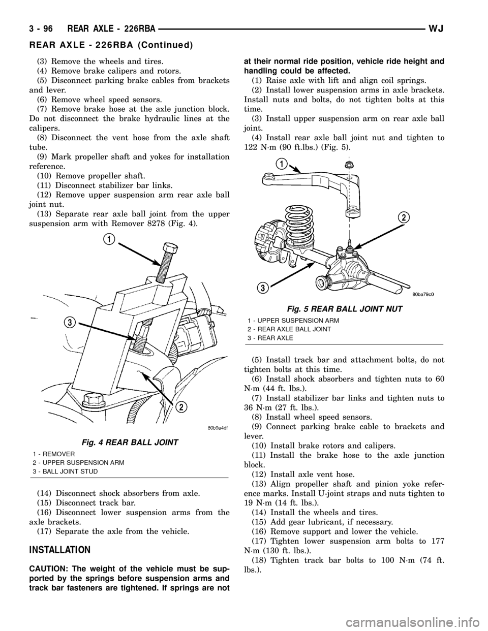
suspension arm with Remover 8278 (Fig. 4).
(14) Disconnect shock absorbers from axle.
(15) Disconnect track bar.
(16) Disconnect lower suspension arms from the
axle brackets.
(17) Separate the axle from the vehicle.
INSTALLATION
CAUTION: The weight of the vehicle must be sup-
ported by the springs before suspension arms and
track bar fasteners are tightened. If springs are not
at their normal ride position, vehicle ride height and
handling could be affected.
(1) Raise axle with lift and align coil springs.
(2) Install lower suspension arms in axle brackets.
Install nuts and bolts, do not tighten bolts at this
time.
(3) Install upper suspension arm on rear axle ball
joint.
(4) Install rear axle ball joint nut and tighten to
122 N´m (90 ft.lbs.) (Fig. 5).
(5) Install track bar and attachment bolts, do not
tighten bolts at this time.
(6) Install shock absorbers and tighten nuts to 60
N´m (44 ft. lbs.).(7) Install stabilizer bar links and tighten nuts to
36 N´m (27 ft. lbs.).
(8) Install wheel speed sensors.
(9) Connect parking brake cable to brackets and
lever.
(10) Install brake rotors and calipers.
(11) Install the brake hose to the axle junction
block.
(12) Install axle vent hose.
(13) Align propeller shaft and pinion yoke refer-
ence marks. Install U-joint straps and nuts tighten to
19 N´m (14 ft. lbs.).
(14) Install the wheels and tires.
(15) Add gear lubricant, if necessary.
(16) Remove support and lower the vehicle.
(17) Tighten lower suspension arm bolts to 177
N´m (130 ft. lbs.).
(18) Tighten track bar bolts to 100 N´m (74 ft.
lbs.).
ADJUSTMENTS
Ring and pinion gears are supplied as matched
sets only. The identifying numbers for the ring and
pinion gear are etched into the face of each gear (Fig.
6). A plus (+) number, minus (±) number or zero (0) is
etched into the face of the pinion gear. This number
is the amount (in thousandths of an inch) the depth
varies from the standard depth setting of a pinion
etched with a (0). The standard setting from the cen-
ter line of the ring gear to the back face of the pinion
is 96.850 mm (3.813 in.). The standard depth pro-
vides the best gear tooth contact pattern. Refer to
Backlash and Contact Pattern Analysis paragraph in
this section for additional information.
Fig. 4 REAR BALL JOINT
1 - REMOVER
2 - UPPER SUSPENSION ARM
3 - BALL JOINT STUD
Fig. 5 REAR BALL JOINT NUT
1 - UPPER SUSPENSION ARM
2 - REAR AXLE BALL JOINT
3 - REAR AXLE
3 - 56 REAR AXLE - 198RBIWJ
REAR AXLE - 198RBI (Continued)
Page 120 of 2199

(7) Check rotating torque with an inch pound
torque wrench (Fig. 44). The rotating torque of the
pinion gear should be, the reading recorded during
removal plus an additional 0.56 N´m (5 in. lbs.).
(8) Install propeller shaft with reference marks
align.
(9) Install rear brake calipers and rotors (Refer to
5 - BRAKES/HYDRAULIC/MECHANICAL/ROTORS
- INSTALLATION).
(10) Add gear lubricant, if necessary.
(11) Install wheel and tire assemblies.
(12) Remove supports and lower vehicle.
DIFFERENTIAL
REMOVAL
(1) Raise and support vehicle.
(2) Remove fill hole plug from the differential
housing cover.
(3) Remove differential housing cover and drain
fluid.
(4) Clean the housing cavity with flushing oil, light
engine oil or lint free cloth.
NOTE: Do not use water, steam, kerosene or gaso-
line for cleaning.
(5) Remove axle shafts.(6)
Note the reference letters stamped on the bearing
caps and housing machined sealing surface (Fig. 45).
(7) Loosen the differential bearing cap bolts.
(8) Position Spreader W-129-B with Adapter Kit
6987B on differential locating holes (Fig. 46). Install
holddown clamps and tighten the turnbuckle finger-
tight.
Fig. 44 PINION ROTATING TORQUE
1 - TORQUE WRENCH
2 - PINION YOKE
Fig. 45 BEARING CAP REFERENCE
1 - REFERENCE LETTERS
2 - REFERENCE LETTERS
Fig. 46 SPREADER LOCATION
1 - DIFFERENTIAL HOUSING
2 - DOWEL
3 - SAFETY HOLD DOWN
4 - SPREADER
5 - TURNBUCKLE
WJREAR AXLE - 198RBI 3 - 75
COLLAPSIBLE SPACER (Continued)
Page 141 of 2199

(3) Remove the wheels and tires.
(4) Remove brake calipers and rotors.
(5) Disconnect parking brake cables from brackets
and lever.
(6) Remove wheel speed sensors.
(7) Remove brake hose at the axle junction block.
Do not disconnect the brake hydraulic lines at the
calipers.
(8) Disconnect the vent hose from the axle shaft
tube.
(9) Mark propeller shaft and yokes for installation
reference.
(10) Remove propeller shaft.
(11) Disconnect stabilizer bar links.
(12) Remove upper suspension arm rear axle ball
joint nut.
(13) Separate rear axle ball joint from the upper
suspension arm with Remover 8278 (Fig. 4).
(14) Disconnect shock absorbers from axle.
(15) Disconnect track bar.
(16) Disconnect lower suspension arms from the
axle brackets.
(17) Separate the axle from the vehicle.
INSTALLATION
CAUTION: The weight of the vehicle must be sup-
ported by the springs before suspension arms and
track bar fasteners are tightened. If springs are notat their normal ride position, vehicle ride height and
handling could be affected.
(1) Raise axle with lift and align coil springs.
(2) Install lower suspension arms in axle brackets.
Install nuts and bolts, do not tighten bolts at this
time.
(3) Install upper suspension arm on rear axle ball
joint.
(4) Install rear axle ball joint nut and tighten to
122 N´m (90 ft.lbs.) (Fig. 5).
(5) Install track bar and attachment bolts, do not
tighten bolts at this time.
(6) Install shock absorbers and tighten nuts to 60
N´m (44 ft. lbs.).
(7) Install stabilizer bar links and tighten nuts to
36 N´m (27 ft. lbs.).
(8) Install wheel speed sensors.
(9) Connect parking brake cable to brackets and
lever.
(10) Install brake rotors and calipers.
(11) Install the brake hose to the axle junction
block.
(12) Install axle vent hose.
(13) Align propeller shaft and pinion yoke refer-
ence marks. Install U-joint straps and nuts tighten to
19 N´m (14 ft. lbs.).
(14) Install the wheels and tires.
(15) Add gear lubricant, if necessary.
(16) Remove support and lower the vehicle.
(17) Tighten lower suspension arm bolts to 177
N´m (130 ft. lbs.).
(18) Tighten track bar bolts to 100 N´m (74 ft.
lbs.).
Fig. 4 REAR BALL JOINT
1 - REMOVER
2 - UPPER SUSPENSION ARM
3 - BALL JOINT STUD
Fig. 5 REAR BALL JOINT NUT
1 - UPPER SUSPENSION ARM
2 - REAR AXLE BALL JOINT
3 - REAR AXLE
3 - 96 REAR AXLE - 226RBAWJ
REAR AXLE - 226RBA (Continued)
Page 160 of 2199

NOTE: If more than 380 N´m (280 ft. lbs.) torque is
required to crush the collapsible spacer, the spacer
is defective and must be replaced.
(7) Check rotating torque with an inch pound
torque wrench (Fig. 44). The rotating torque of the
pinion gear should be, the reading recorded during
removal plus an additional 0.56 N´m (5 in. lbs.).
(8)
Install propeller shaft with reference marks align.
(9) Install rear brake rotors and calipers.
(10) Add gear lubricant, if necessary.
(11) Install wheel and tire assemblies.
(12) Remove supports and lower vehicle.
DIFFERENTIAL
REMOVAL
(1) Raise and support vehicle.
(2) Remove fill hole plug from the differential
housing cover.
(3) Remove differential housing cover and drain
fluid.
(4) Clean the housing cavity with flushing oil, light
engine oil or lint free cloth.
NOTE: Do not use water, steam, kerosene or gaso-
line for cleaning.
(5) Remove axle shafts.(6)
Note the reference letters stamped on the bearing
caps and housing machined sealing surface (Fig. 45).
(7) Loosen the differential bearing cap bolts.
(8) Position Spreader W-129-B with Adapter Kit
6987B on differential locating holes (Fig. 46). Install
holddown clamps and tighten the turnbuckle finger-
tight.
Fig. 44 PINION ROTATING TORQUE
1 - TORQUE WRENCH
2 - PINION YOKE
Fig. 45 BEARING CAP REFERENCE
1 - REFERENCE LETTERS
2 - REFERENCE LETTERS
Fig. 46 SPREADER LOCATION
1 - DIFFERENTIAL HOUSING
2 - DOWEL
3 - SAFETY HOLD DOWN
4 - SPREADER
5 - TURNBUCKLE
WJREAR AXLE - 226RBA 3 - 115
COLLAPSIBLE SPACER (Continued)
Page 176 of 2199

BRAKES
TABLE OF CONTENTS
page page
BRAKES - BASE........................... 1BRAKES - ABS........................... 41
BRAKES - BASE
TABLE OF CONTENTS
page page
BRAKES - BASE
DESCRIPTION..........................2
DIAGNOSIS AND TESTING - BASE BRAKE
SYSTEM.............................2
STANDARD PROCEDURE
STANDARD PROCEDURE - MANUAL
BLEEDING............................5
STANDARD PROCEDURE - PRESSURE
BLEEDING............................5
SPECIFICATIONS
BRAKE COMPONENTS..................6
TORQUE CHART......................6
SPECIAL TOOLS
BASE BRAKES........................7
BRAKE FLUID LEVEL SWITCH
REMOVAL.............................7
INSTALLATION..........................7
RED BRAKE WARN INDICATOR SWITCH
DESCRIPTION..........................7
OPERATION............................7
DIAGNOSIS AND TESTING - RED BRAKE
WARNING LAMP.......................7
ADJUSTABLE PEDAL SWITCH
REMOVAL.............................8
INSTALLATION..........................8
BRAKE LINES
DESCRIPTION..........................8
DIAGNOSIS AND TESTING - BRAKE HOSES
AND LINES...........................8
STANDARD PROCEDURE
STANDARD PROCEDURE - DOUBLE
INVERTED FLARING....................9
STANDARD PROCEDURE - ISO FLARING . . . 9
BRAKE PADS / SHOES
DESCRIPTION
DESCRIPTION - FRONT DISC BRAKE
SHOES.............................10DESCRIPTION - REAR DISC BRAKE SHOES . 10
OPERATION
OPERATION - FRONT DISC BRAKE SHOES . 10
OPERATION - REAR DISC BRAKE SHOES . . 10
REMOVAL
REMOVAL- FRONT DISC BRAKE SHOES . . . 11
REMOVAL - REAR DISC BRAKE SHOES....12
INSTALLATION
INSTALLATION - FRONT DISC BRAKE
SHOES.............................13
INSTALLATION - REAR DISC BRAKE
SHOES.............................14
DISC BRAKE CALIPERS
REMOVAL
REMOVAL - FRONT DISC BRAKE CALIPER . 14
REMOVAL - REAR DISC BRAKE CALIPER . . 15
DISASSEMBLY
DISASSEMBLY - FRONT DISC BRAKE
CALIPER............................17
DISASSEMBLY - REAR DISC BRAKE
CALIPER............................18
CLEANING - DISC BRAKE CALIPER.........19
INSPECTION - DISC BRAKE CALIPER.......19
ASSEMBLY
ASSEMBLY - FRONT DISC BRAKE CALIPER . 20
ASSEMBLY - REAR DISC BRAKE CALIPER . 21
INSTALLATION
INSTALLATION - FRONT DISC BRAKE
CALIPER............................22
INSTALLATION - REAR DISC BRAKE
CALIPER............................22
FLUID
DIAGNOSIS AND TESTING - BRAKE FLUID
CONTAMINATION.....................22
SPECIFICATIONS
BRAKE FLUID........................23
FLUID RESERVOIR
REMOVAL.............................23
WJBRAKES 5 - 1
Page 177 of 2199

INSTALLATION.........................23
MASTER CYLINDER
DESCRIPTION.........................23
OPERATION...........................24
DIAGNOSIS AND TESTING - MASTER
CYLINDER/POWER BOOSTER...........24
STANDARD PROCEDURE - MASTER
CYLINDER BLEEDING PROCEDURE......25
REMOVAL.............................25
INSTALLATION.........................25
PEDAL
DESCRIPTION
DESCRIPTION - STANDARD PEDAL.......25
DESCRIPTION - ADJUSTABLE PEDALS....25
OPERATION...........................26
REMOVAL
REMOVAL - NON-ADJUSTABLE PEDAL....26
REMOVAL - ADJUSTABLE PEDALS........27
INSTALLATION
INSTALLATION - NON-ADJUSTABLE PEDAL . 28
INSTALLATION - ADJUSTABLE PEDALS....28
PEDAL MOTOR
REMOVAL.............................28
INSTALLATION.........................28
POWER BRAKE BOOSTER
DESCRIPTION.........................29
OPERATION...........................29
REMOVAL.............................31
INSTALLATION.........................31
ROTORS
DIAGNOSIS AND TESTING
DIAGNOSIS AND TESTING - FRONT DISC
BRAKE ROTOR.......................31DIAGNOSIS AND TESTING - REAR DISC
BRAKE ROTOR.......................32
STANDARD PROCEDURE - DISC ROTOR
MACHINING..........................33
REMOVAL
REMOVAL - FRONT DISC BRAKE ROTOR . . 33
REMOVAL - REAR DISC BRAKE ROTOR . . . 33
INSTALLATION
INSTALLATION - FRONT DISC BRAKE
ROTOR .............................34
INSTALLATION - REAR DISC BRAKE
ROTOR .............................34
PARKING BRAKE
OPERATION...........................34
DIAGNOSIS AND TESTING - PARKING BRAKE . 34
CABLES
REMOVAL
REMOVAL - FRONT PARKING BRAKE
CABLE..............................35
REMOVAL - REAR PARKING BRAKE
CABLES............................36
INSTALLATION
INSTALLATION - FRONT PARKING BRAKE
CABLE..............................37
INSTALLATION - REAR PARKING BRAKE
CABLES............................37
LEVER
REMOVAL.............................38
INSTALLATION.........................39
SHOES
REMOVAL.............................39
INSTALLATION.........................39
ADJUSTMENTS - PARKING BRAKE SHOE....40
BRAKES - BASE
DESCRIPTION
Dual piston disc brake calipers are used on the
front. Single piston disc brake calipers are used on
the rear. Ventilated disc brake rotors are used on the
front and solid rotors are used on the rear.
Power brake assist is supplied by a vacuum oper-
ated, dual diaphragm power brake booster. The mas-
ter cylinder used for all applications has an
aluminum body and nylon reservoir with single filler
cap. A fluid level indicator is mounted to the side of
the reservoir.
The braking force of the rear wheels is controlled
by electronic brake distribution (EBD). The EBD
functions like a rear proportioning valve. The EBD
system uses the ABS system to control the slip of the
rear wheels in partial braking range. The braking
force of the rear wheels is controlled electronically by
using the inlet and outlet valves located in the HCU.
Factory installed brake linings on all models con-
sists of organic base material combined with metallic
particles.
DIAGNOSIS AND TESTING - BASE BRAKE
SYSTEM
Base brake components consist of the brake shoes,
calipers, rear park brake drums/rotors, front brake
rotors, brake lines, master cylinder, booster, HCU
and parking brake shoes.
Brake diagnosis involves determining if the prob-
lem is related to a mechanical, hydraulic, electrical
or vacuum operated component.
The first diagnosis step is the preliminary check.
PRELIMINARY BRAKE CHECK
(1) Check condition of tires and wheels. Damaged
wheels and worn, damaged, or underinflated tires
can cause pull, shudder, vibration, and a condition
similar to grab.
5 - 2 BRAKES - BASEWJ