2003 JEEP GRAND CHEROKEE Seat position
[x] Cancel search: Seat positionPage 1342 of 2199
(19) Remove the retaining bolt and the camshaft
drive gear.
CAUTION: Do not allow the engine to rotate. severe
damage to the valve train can occur.
CAUTION: Do not overlook the four smaller bolts at
the front of the cylinder head. Do not attempt to
remove the cylinder head without removing these
four bolts.
CAUTION: Do not hold or pry on the camshaft tar-
get wheel for any reason. A damaged target wheel
can result in a vehicle no start condition.
NOTE: The cylinder head is attached to the cylinder
block with fourteen bolts.
(20) Remove the cylinder head retaining bolts.
(21) Remove the cylinder head and gasket. Discard
the gasket.
CAUTION: Do not lay the cylinder head on its gas-
ket sealing surface, do to the design of the cylinder
head gasket any distortion to the cylinder head
sealing surface may prevent the gasket from prop-
erly sealing resulting in leaks.
CLEANING
To ensure engine gasket sealing, proper surface
preparation must be performed, especially with the
use of aluminum engine components. (Refer to 9 -
ENGINE - STANDARD PROCEDURE)
INSPECTION
(1) Inspect the cylinder head for out-of-flatness,
using a straightedge and a feeler gauge. If tolerances
exceed 0.0508 mm (0.002 in.) replace the cylinder
head.
(2) Inspect the valve seats for damage. Service the
valve seats as necessary.
(3) Inspect the valve guides for wear, cracks or
looseness. If either condition exist, replace the cylin-
der head.
INSTALLATION
NOTE: The cylinder head bolts are tightened using
a torque plus angle procedure. The bolts must be
examined BEFORE reuse. If the threads are necked
down the bolts should be replaced.
Necking can be checked by holding a straight edge
against the threads. If all the threads do not contact
the scale, the bolt should be replaced (Fig. 13).
CAUTION: When cleaning cylinder head and cylin-
der block surfaces, DO NOT use a metal scraper
because the surfaces could be cut or ground. Use
only a wooden or plastic scraper.
(1) Clean the cylinder head and cylinder block
mating surfaces (Refer to 9 - ENGINE - STANDARD
PROCEDURE).
(2) Position the new cylinder head gasket on the
locating dowels.
CAUTION: When installing cylinder head, use care
not damage the tensioner arm or the guide arm.
(3) Position the cylinder head onto the cylinder
block. Make sure the cylinder head seats fully over
the locating dowels.
NOTE: The four smaller cylinder head mounting
bolts require sealant to be added to them before
installing. Failure to do so may cause leaks.
(4) Lubricate the cylinder head bolt threads with
clean engine oil and install the ten M10 bolts.
(5) Coat the four M8 cylinder head bolts with
Mopar Lock and Seal Adhesivethen install the
bolts.
NOTE: The cylinder head bolts are tightened using
an angle torque procedure, however, the bolts are
not a torque-to-yield design.
(6) Tighten the bolts in sequence (Fig. 30) using
the following steps and torque values:
²Step 1: Tighten bolts 1±10, 27 N´m (20 ft. lbs.).
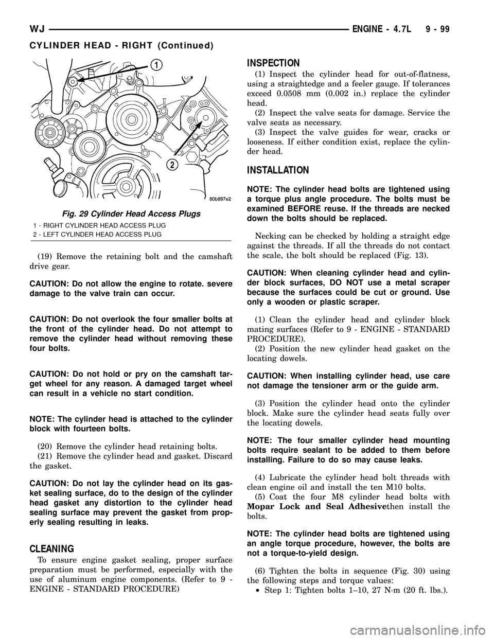
Fig. 29 Cylinder Head Access Plugs
1 - RIGHT CYLINDER HEAD ACCESS PLUG
2 - LEFT CYLINDER HEAD ACCESS PLUG
WJENGINE - 4.7L 9 - 99
CYLINDER HEAD - RIGHT (Continued)
Page 1348 of 2199
STANDARD PROCEDUREÐREFACING
NOTE: Valve seats that are worn or burned can be
reworked, provided that correct angle and seat
width are maintained. Otherwise the cylinder head
must be replaced.
NOTE: When refacing valves and valve seats, it is
important that the correct size valve guide pilot be
used for reseating stones. A true and complete sur-
face must be obtained.
(1) Using a suitable dial indicator measure the
center of the valve seat Total run out must not
exceed 0.051 mm (0.002 in).
(2) Apply a small amount of Prussian blue to the
valve seat, insert the valve into the cylinder head,
while applying light pressure on the valve rotate the
valve. Remove the valve and examine the valve face.
If the blue is transferred below the top edge of the
valve face, lower the valve seat using a 15 degree
stone. If the blue is transferred to the bottom edge of
the valve face, raise the valve seat using a 65 degree
stone.
(3) When the seat is properly positioned the width
of the intake seat must be 1.75 ± 2.36 mm (0.0689 ±
0.0928 in.) and the exhaust seat must be 1.71 ± 2.32
mm (0.0673 ± 0.0911 in.).
(4) Check the valve spring installed height after
refacing the valve and seat. The installed height for
both intake and exhaust valve springs must not
exceed 41.44 mm (1.6315 in.).
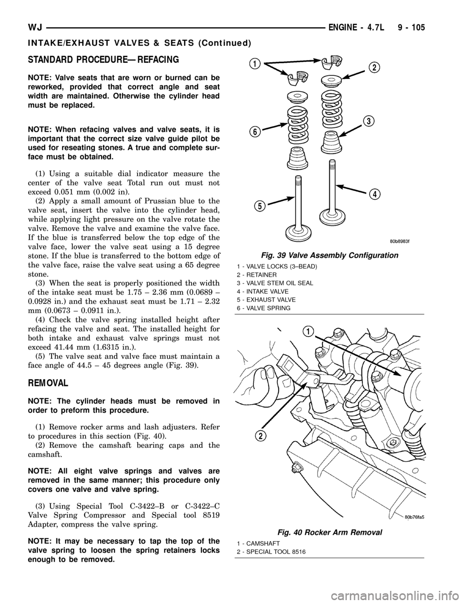
(5) The valve seat and valve face must maintain a
face angle of 44.5 ± 45 degrees angle (Fig. 39).
REMOVAL
NOTE: The cylinder heads must be removed in
order to preform this procedure.
(1) Remove rocker arms and lash adjusters. Refer
to procedures in this section (Fig. 40).
(2) Remove the camshaft bearing caps and the
camshaft.
NOTE: All eight valve springs and valves are
removed in the same manner; this procedure only
covers one valve and valve spring.
(3) Using Special Tool C-3422±B or C-3422±C
Valve Spring Compressor and Special tool 8519
Adapter, compress the valve spring.
NOTE: It may be necessary to tap the top of the
valve spring to loosen the spring retainers locks
enough to be removed.
Fig. 39 Valve Assembly Configuration
1 - VALVE LOCKS (3±BEAD)
2 - RETAINER
3 - VALVE STEM OIL SEAL
4 - INTAKE VALVE
5 - EXHAUST VALVE
6 - VALVE SPRING
Fig. 40 Rocker Arm Removal
1 - CAMSHAFT
2 - SPECIAL TOOL 8516
WJENGINE - 4.7L 9 - 105
INTAKE/EXHAUST VALVES & SEATS (Continued)
Page 1349 of 2199
(4) Remove the two spring retainer lock halves.
NOTE: the valve spring is under tension use care
when releasing the valve spring compressor.
(5) Remove the valve spring compressor.
(6) Remove the spring retainer, and the spring.
NOTE: Check for sharp edges on the keeper
grooves. Remove any burrs from the valve stem
before removing the valve from the cylinder head.
(7) Remove the valve from the cylinder head.
NOTE: The valve stem seals are common between
intake and exhaust.
(8) Remove the valve stem seal. Mark the valve for
proper installation.
TESTING VALVE SPRINGS
NOTE: Whenever the valves are removed from the
cylinder head it is recommended that the valve
springs be inspected and tested for reuse.
Inspect the valve springs for physical signs of wear
or damage. Turn table of tool C-647 until surface is
in line with the 40.69 mm (1.602 in.) mark on the
threaded stud and the zero mark on the front. Place
spring over the stud on the table and lift compress-
ing lever to set tone device. Pull on torque wrench
until Ping is heard. Take reading on torque wrench
at this instant. Multiply this reading by two. This
will give the spring load at test length. Fractional
measurements are indicated on the table for finer
adjustments. Refer to Specifications Section to obtain
specified height and allowable tensions. Replace any
springs that do not meet specifications. (Fig. 41)
INSTALLATION
(1) coat the valve stem with clean engine oil and
insert it into the cylinder head.
(2) Install the valve stem seal. make sure the seal
is fully seated and that the garter spring at the top
of the seal is intact.
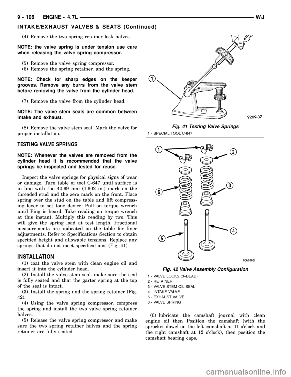
(3) Install the spring and the spring retainer (Fig.
42).
(4) Using the valve spring compressor, compress
the spring and install the two valve spring retainer
halves.
(5) Release the valve spring compressor and make
sure the two spring retainer halves and the spring
retainer are fully seated.(6) lubricate the camshaft journal with clean
engine oil then Position the camshaft (with the
sprocket dowel on the left camshaft at 11 o'clock and
the right camshaft at 12 o'clock), then position the
camshaft bearing caps.
Fig. 41 Testing Valve Springs
1 - SPECIAL TOOL C-647
Fig. 42 Valve Assembly Configuration
1 - VALVE LOCKS (3±BEAD)
2 - RETAINER
3 - VALVE STEM OIL SEAL
4 - INTAKE VALVE
5 - EXHAUST VALVE
6 - VALVE SPRING
9 - 106 ENGINE - 4.7LWJ
INTAKE/EXHAUST VALVES & SEATS (Continued)
Page 1350 of 2199
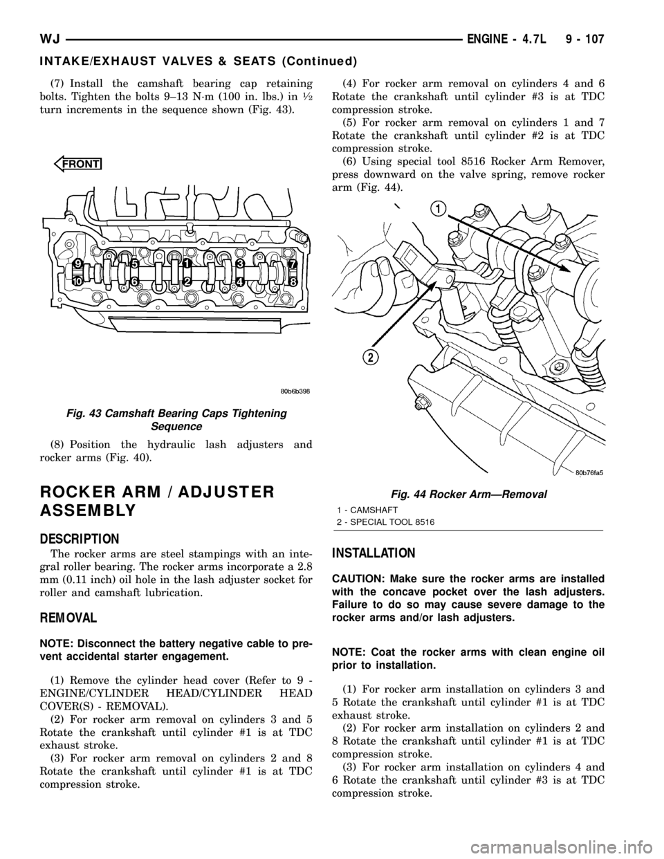
(7) Install the camshaft bearing cap retaining
bolts. Tighten the bolts 9±13 N´m (100 in. lbs.) in1¤2
turn increments in the sequence shown (Fig. 43).
(8) Position the hydraulic lash adjusters and
rocker arms (Fig. 40).
ROCKER ARM / ADJUSTER
ASSEMBLY
DESCRIPTION
The rocker arms are steel stampings with an inte-
gral roller bearing. The rocker arms incorporate a 2.8
mm (0.11 inch) oil hole in the lash adjuster socket for
roller and camshaft lubrication.
REMOVAL
NOTE: Disconnect the battery negative cable to pre-
vent accidental starter engagement.
(1) Remove the cylinder head cover (Refer to 9 -
ENGINE/CYLINDER HEAD/CYLINDER HEAD
COVER(S) - REMOVAL).
(2) For rocker arm removal on cylinders 3 and 5
Rotate the crankshaft until cylinder #1 is at TDC
exhaust stroke.
(3) For rocker arm removal on cylinders 2 and 8
Rotate the crankshaft until cylinder #1 is at TDC
compression stroke.(4) For rocker arm removal on cylinders 4 and 6
Rotate the crankshaft until cylinder #3 is at TDC
compression stroke.
(5) For rocker arm removal on cylinders 1 and 7
Rotate the crankshaft until cylinder #2 is at TDC
compression stroke.
(6) Using special tool 8516 Rocker Arm Remover,
press downward on the valve spring, remove rocker
arm (Fig. 44).
INSTALLATION
CAUTION: Make sure the rocker arms are installed
with the concave pocket over the lash adjusters.
Failure to do so may cause severe damage to the
rocker arms and/or lash adjusters.
NOTE: Coat the rocker arms with clean engine oil
prior to installation.
(1) For rocker arm installation on cylinders 3 and
5 Rotate the crankshaft until cylinder #1 is at TDC
exhaust stroke.
(2) For rocker arm installation on cylinders 2 and
8 Rotate the crankshaft until cylinder #1 is at TDC
compression stroke.
(3) For rocker arm installation on cylinders 4 and
6 Rotate the crankshaft until cylinder #3 is at TDC
compression stroke.
Fig. 43 Camshaft Bearing Caps Tightening
Sequence
Fig. 44 Rocker ArmÐRemoval
1 - CAMSHAFT
2 - SPECIAL TOOL 8516
WJENGINE - 4.7L 9 - 107
INTAKE/EXHAUST VALVES & SEATS (Continued)
Page 1360 of 2199
CRANKSHAFT OIL SEAL -
REAR
REMOVAL
NOTE: This procedure can be performed in vehicle.
(1) If being preformed in vehicle, remove the
transmission.
(2) Remove the flexplate (Refer to 9 - ENGINE/
ENGINE BLOCK/FLEX PLATE - REMOVAL).
NOTE: The crankshaft oil seal CAN NOT be reused
after removal.
NOTE: The crankshaft rear oil seal remover Special
Tool 8506 must be installed deeply into the seal.
Continue to tighten the removal tool into the seal
until the tool can not be turned farther. Failure to
install tool correctly the first time will cause tool to
pull free of seal without removing seal from engine.
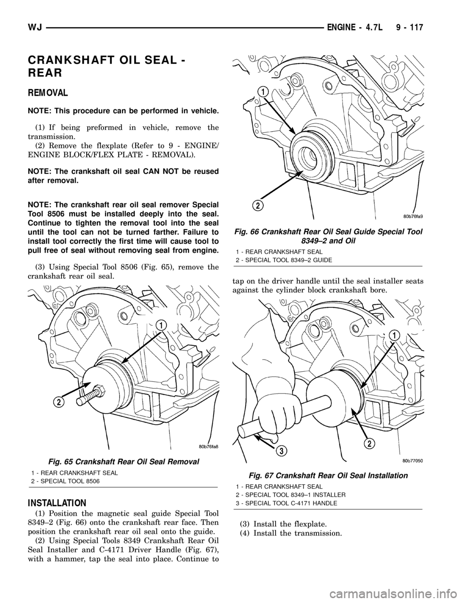
(3) Using Special Tool 8506 (Fig. 65), remove the
crankshaft rear oil seal.
INSTALLATION
(1) Position the magnetic seal guide Special Tool
8349±2 (Fig. 66) onto the crankshaft rear face. Then
position the crankshaft rear oil seal onto the guide.
(2) Using Special Tools 8349 Crankshaft Rear Oil
Seal Installer and C-4171 Driver Handle (Fig. 67),
with a hammer, tap the seal into place. Continue totap on the driver handle until the seal installer seats
against the cylinder block crankshaft bore.
(3) Install the flexplate.
(4) Install the transmission.
Fig. 65 Crankshaft Rear Oil Seal Removal
1 - REAR CRANKSHAFT SEAL
2 - SPECIAL TOOL 8506
Fig. 66 Crankshaft Rear Oil Seal Guide Special Tool
8349±2 and Oil
1 - REAR CRANKSHAFT SEAL
2 - SPECIAL TOOL 8349±2 GUIDE
Fig. 67 Crankshaft Rear Oil Seal Installation
1 - REAR CRANKSHAFT SEAL
2 - SPECIAL TOOL 8349±1 INSTALLER
3 - SPECIAL TOOL C-4171 HANDLE
WJENGINE - 4.7L 9 - 117
Page 1374 of 2199
CRANKCASE OIL LEVEL INSPECTION
CAUTION: Do not overfill crankcase with engine oil,
pressure loss or oil foaming can result.
Inspect engine oil level approximately every 800
kilometers (500 miles). Unless the engine has exhib-
ited loss of oil pressure, run the engine for about five
minutes before checking oil level. Checking engine oil
level on a cold engine is not accurate.
To ensure proper lubrication of an engine, the
engine oil must be maintained at an acceptable level.
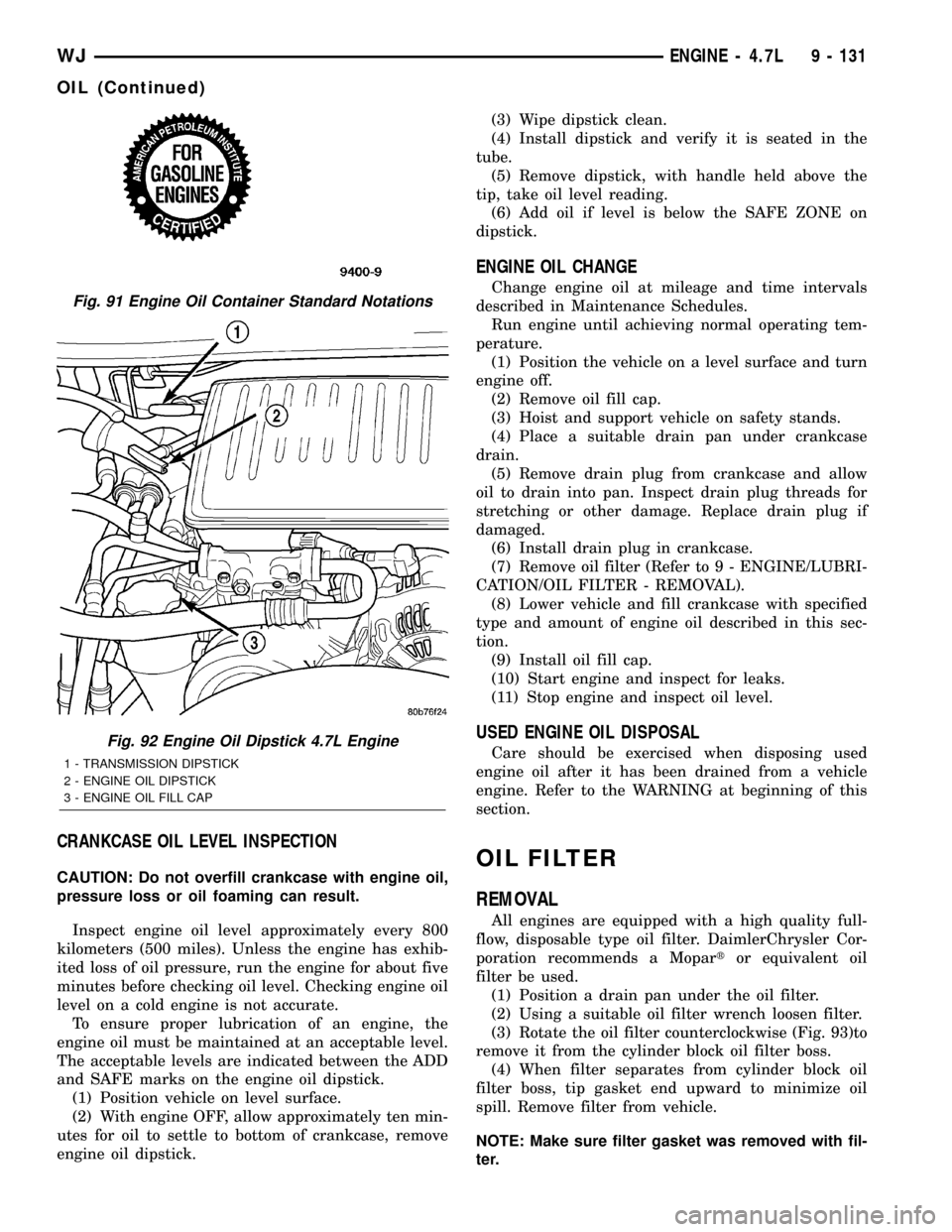
The acceptable levels are indicated between the ADD
and SAFE marks on the engine oil dipstick.
(1) Position vehicle on level surface.
(2) With engine OFF, allow approximately ten min-
utes for oil to settle to bottom of crankcase, remove
engine oil dipstick.(3) Wipe dipstick clean.
(4) Install dipstick and verify it is seated in the
tube.
(5) Remove dipstick, with handle held above the
tip, take oil level reading.
(6) Add oil if level is below the SAFE ZONE on
dipstick.
ENGINE OIL CHANGE
Change engine oil at mileage and time intervals
described in Maintenance Schedules.
Run engine until achieving normal operating tem-
perature.
(1) Position the vehicle on a level surface and turn
engine off.
(2) Remove oil fill cap.
(3) Hoist and support vehicle on safety stands.
(4) Place a suitable drain pan under crankcase
drain.
(5) Remove drain plug from crankcase and allow
oil to drain into pan. Inspect drain plug threads for
stretching or other damage. Replace drain plug if
damaged.
(6) Install drain plug in crankcase.
(7) Remove oil filter (Refer to 9 - ENGINE/LUBRI-
CATION/OIL FILTER - REMOVAL).
(8) Lower vehicle and fill crankcase with specified
type and amount of engine oil described in this sec-
tion.
(9) Install oil fill cap.
(10) Start engine and inspect for leaks.
(11) Stop engine and inspect oil level.
USED ENGINE OIL DISPOSAL
Care should be exercised when disposing used
engine oil after it has been drained from a vehicle
engine. Refer to the WARNING at beginning of this
section.
OIL FILTER
REMOVAL
All engines are equipped with a high quality full-
flow, disposable type oil filter. DaimlerChrysler Cor-
poration recommends a Mopartor equivalent oil
filter be used.
(1) Position a drain pan under the oil filter.
(2) Using a suitable oil filter wrench loosen filter.
(3) Rotate the oil filter counterclockwise (Fig. 93)to
remove it from the cylinder block oil filter boss.
(4) When filter separates from cylinder block oil
filter boss, tip gasket end upward to minimize oil
spill. Remove filter from vehicle.
NOTE: Make sure filter gasket was removed with fil-
ter.
Fig. 91 Engine Oil Container Standard Notations
Fig. 92 Engine Oil Dipstick 4.7L Engine
1 - TRANSMISSION DIPSTICK
2 - ENGINE OIL DIPSTICK
3 - ENGINE OIL FILL CAP
WJENGINE - 4.7L 9 - 131
OIL (Continued)
Page 1437 of 2199

(9) Disconnect speed control cable at throttle body
(if equipped). Refer to Speed Control Cable.
(10) Disconnect automatic transmission cable at
throttle body (if equipped).
(11) Remove cable routing bracket at intake mani-
fold.
(12) Clean dirt/debris from each fuel injector at
intake manifold.
(13) Remove fuel rail mounting nuts/bolts (Fig.
24).
(14) Remove fuel rail by gently rocking until all
fuel injectors have cleared machined holes at intake
manifold.
(15) If fuel injectors are to be removed, refer to
Fuel Injector Removal/Installation.
INSTALLATION
INSTALLATION - 4.7L
(1) If fuel injectors are to be installed, refer to Fuel
Injector Removal/Installation.
(2) Apply a small amount of engine oil to each fuel
injector o-ring. This will help in fuel rail installation.
(3) Position fuel rail/fuel injector assembly to
machined injector openings in cylinder head.
(4) Guide each injector into cylinder head. Be care-
ful not to tear injector o-rings.(5) Pushrightside of fuel rail down until fuel
injectors have bottomed on cylinder head shoulder.
Pushleftfuel rail down until injectors have bot-
tomed on cylinder head shoulder.
(6) Install 4 fuel rail mounting bolts and tighten to
27 N´m (20 ft. lbs.).
(7) Install ignition coils. Refer to Ignition Coil
Removal/Installation.
(8) Connect electrical connectors to throttle body.
(9) Connect electrical connectors to MAP and IAT
sensors.
(10) Connect electrical connectors at all fuel injec-
tors. To install connector, refer to (Fig. 23). Push con-
nector onto injector (1) and then push and lock red
colored slider (2). Verify connector is locked to injec-
tor by lightly tugging on connector.
(11) Connect vacuum lines to throttle body.
(12) Connect fuel line latch clip and fuel line to
fuel rail. Refer to Quick-Connect Fittings.
(13) Connect wiring to rear of generator.
(14) Install air box to throttle body.
(15) Install air duct to air box.
(16) Connect battery cable to battery.
(17) Start engine and check for leaks.
INSTALLATION - 4.0L
(1) If fuel injectors are to be installed, refer to Fuel
Injector Removal/Installation.
(2) Clean each injector bore at intake manifold.
(3) Apply a small amount of clean engine oil to
each injector o-ring. This will aid in installation.
(4) Position tips of all fuel injectors into the corre-
sponding injector bore in intake manifold. Seat injec-
tors into manifold.
(5) Install and tighten fuel rail mounting bolts to
11 3 N´m (100 25 in. lbs.) torque.
(6) Connect electrical connectors at all fuel injec-
tors. To install connector, refer to (Fig. 25). Push con-
nector onto injector (1) and then push and lock red
colored slider (2). Verify connector is locked to injec-
tor by lightly tugging on connector.
(7) Connect fuel line and fuel line latch clip to fuel
rail. Refer Quick-Connect Fittings.
(8) Install protective cap to pressure test port fit-
ting (if equipped).
(9) Install cable routing bracket to intake mani-
fold.
(10) Connect throttle cable at throttle body.
(11) Connect speed control cable at throttle body (if
equipped).
(12) Connect automatic transmission cable at
throttle body (if equipped).
(13) Install oxygen sensor wiring clip nuts to fuel
rail mounting studs (certain emissions packages
only).
Fig. 25 Remove/Install Injector ConnectorÐ4.0L
Engine
14 - 18 FUEL DELIVERYWJ
FUEL RAIL (Continued)
Page 1475 of 2199
(7) From inside vehicle, install clip holding cable
to dashpanel (Fig. 16).
(8) From inside vehicle, slide throttle cable core
wire into opening in top of pedal arm.
(9) Push cable retainer (clip) into pedal arm open-
ing until it snaps in place.
(10) Before starting engine, operate accelerator
pedal to check for any binding.
INSTALLATION - 4.7L
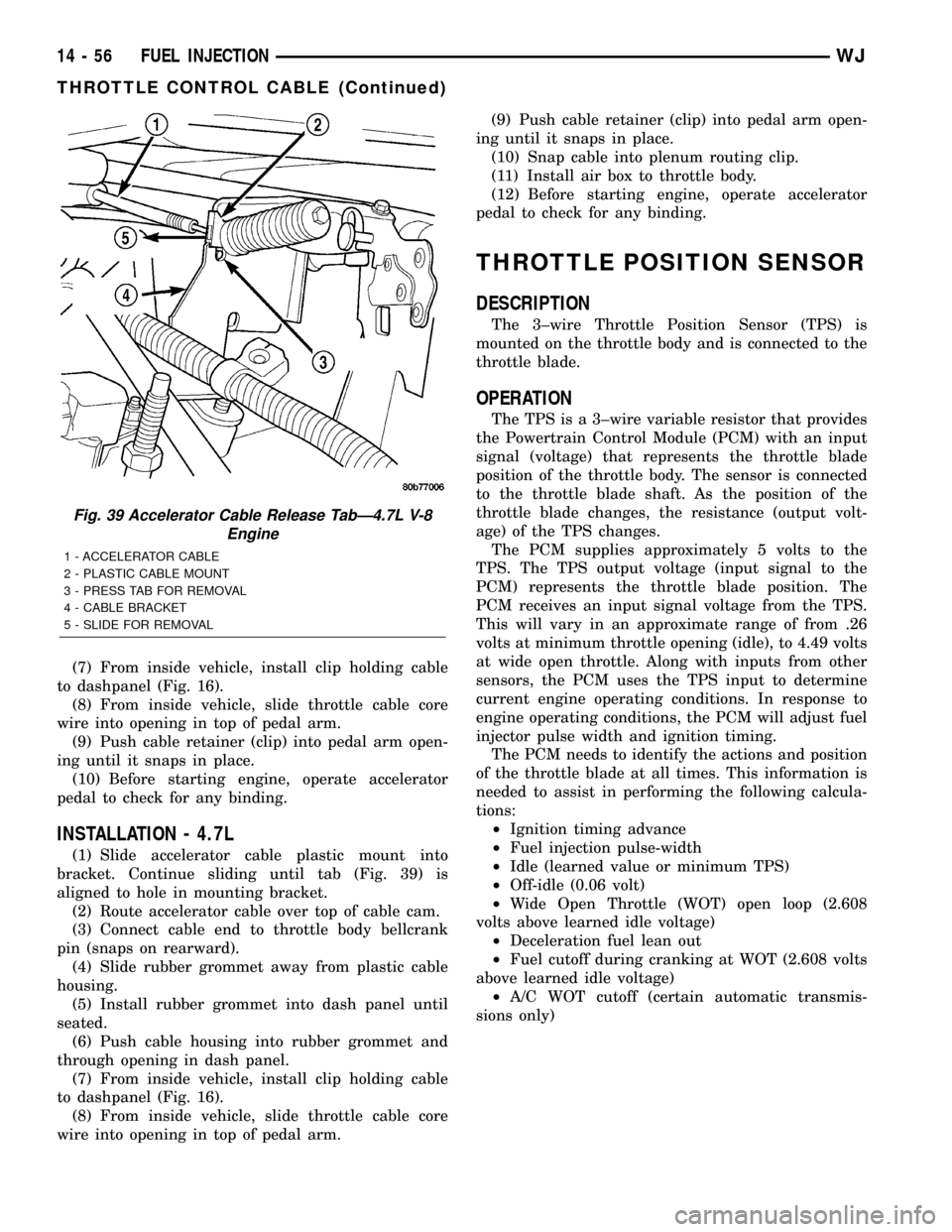
(1) Slide accelerator cable plastic mount into
bracket. Continue sliding until tab (Fig. 39) is
aligned to hole in mounting bracket.
(2) Route accelerator cable over top of cable cam.
(3) Connect cable end to throttle body bellcrank
pin (snaps on rearward).
(4) Slide rubber grommet away from plastic cable
housing.
(5) Install rubber grommet into dash panel until
seated.
(6) Push cable housing into rubber grommet and
through opening in dash panel.
(7) From inside vehicle, install clip holding cable
to dashpanel (Fig. 16).
(8) From inside vehicle, slide throttle cable core
wire into opening in top of pedal arm.(9) Push cable retainer (clip) into pedal arm open-
ing until it snaps in place.
(10) Snap cable into plenum routing clip.
(11) Install air box to throttle body.
(12) Before starting engine, operate accelerator
pedal to check for any binding.
THROTTLE POSITION SENSOR
DESCRIPTION
The 3±wire Throttle Position Sensor (TPS) is
mounted on the throttle body and is connected to the
throttle blade.
OPERATION
The TPS is a 3±wire variable resistor that provides
the Powertrain Control Module (PCM) with an input
signal (voltage) that represents the throttle blade
position of the throttle body. The sensor is connected
to the throttle blade shaft. As the position of the
throttle blade changes, the resistance (output volt-
age) of the TPS changes.
The PCM supplies approximately 5 volts to the
TPS. The TPS output voltage (input signal to the
PCM) represents the throttle blade position. The
PCM receives an input signal voltage from the TPS.
This will vary in an approximate range of from .26
volts at minimum throttle opening (idle), to 4.49 volts
at wide open throttle. Along with inputs from other
sensors, the PCM uses the TPS input to determine
current engine operating conditions. In response to
engine operating conditions, the PCM will adjust fuel
injector pulse width and ignition timing.
The PCM needs to identify the actions and position
of the throttle blade at all times. This information is
needed to assist in performing the following calcula-
tions:
²Ignition timing advance
²Fuel injection pulse-width
²Idle (learned value or minimum TPS)
²Off-idle (0.06 volt)
²Wide Open Throttle (WOT) open loop (2.608
volts above learned idle voltage)
²Deceleration fuel lean out
²Fuel cutoff during cranking at WOT (2.608 volts
above learned idle voltage)
²A/C WOT cutoff (certain automatic transmis-
sions only)
Fig. 39 Accelerator Cable Release TabÐ4.7L V-8
Engine
1 - ACCELERATOR CABLE
2 - PLASTIC CABLE MOUNT
3 - PRESS TAB FOR REMOVAL
4 - CABLE BRACKET
5 - SLIDE FOR REMOVAL
14 - 56 FUEL INJECTIONWJ
THROTTLE CONTROL CABLE (Continued)