2003 JEEP GRAND CHEROKEE speed control
[x] Cancel search: speed controlPage 1320 of 2199
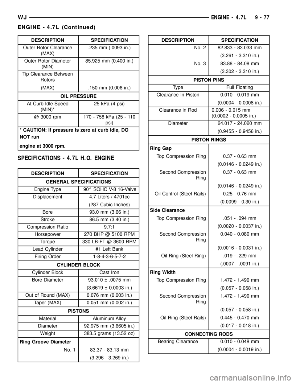
DESCRIPTION SPECIFICATION
Outer Rotor Clearance
(MAX).235 mm (.0093 in.)
Outer Rotor Diameter
(MIN)85.925 mm (0.400 in.)
Tip Clearance Between
Rotors
(MAX) .150 mm (0.006 in.)
OIL PRESSURE
At Curb Idle Speed
(MIN)*25 kPa (4 psi)
@ 3000 rpm 170 - 758 kPa (25 - 110
psi)
* CAUTION: If pressure is zero at curb idle, DO
NOT run
engine at 3000 rpm.
SPECIFICATIONS - 4.7L H.O. ENGINE
DESCRIPTION SPECIFICATION
GENERAL SPECIFICATIONS
Engine Type 90É SOHC V-8 16-Valve
Displacement 4.7 Liters / 4701cc
(287 Cubic Inches)
Bore 93.0 mm (3.66 in.)
Stroke 86.5 mm (3.40 in.)
Compression Ratio 9.7:1
Horsepower 270 BHP @ 5100 RPM
Torque 330 LB-FT @ 3600 RPM
Lead Cylinder #1 Left Bank
Firing Order 1-8-4-3-6-5-7-2
CYLINDER BLOCK
Cylinder Block Cast Iron
Bore Diameter 93.010 .0075 mm
(3.6619 0.0003 in.)
Out of Round (MAX) 0.076 mm (0.003 in.)
Taper (MAX) 0.051 mm (0.002 in.)
PISTONS
Material Aluminum Alloy
Diameter 92.975 mm (3.6605 in.)
Weight 383.5 grams (13.52 oz)
Ring Groove Diameter
No. 1 83.37 - 83.13 mm
(3.296 - 3.269 in.)
DESCRIPTION SPECIFICATION
No. 2 82.833 - 83.033 mm
(3.261 - 3.310 in.)
No. 3 83.88 - 84.08 mm
(3.302 - 3.310 in.)
PISTON PINS
Type Full Floating
Clearance In Piston 0.010 - 0.019 mm
(0.0004 - 0.0008 in.)
Clearance in Rod 0.006 - 0.015 mm
(0.0002 - 0.0005 in.)
Diameter 24.017 - 24.020 mm
(0.9455 - 0.9456 in.)
PISTON RINGS
Ring Gap
Top Compression Ring 0.37 - 0.63 mm
(0.0146 - 0.0249 in.)
Second Compression
Ring0.37 - 0.63 mm
(0.0146 - 0.0249 in.)
Oil Control (Steel Rails) 0.25 - 0.76 mm
(0.0099 - 0.30 in.)
Side Clearance
Top Compression Ring .051 - .094 mm
(0.0020 - 0.0037 in.)
Second Compression
Ring0.040 - 0.080 mm
(0.0016 - 0.0031 in.)
Oil Ring (Steel Ring) .019 - .229 mm
(.0007 - .0091 in.)
Ring Width
Top Compression Ring 1.472 - 1.490 mm
(0.057 - 0.058 in.)
Second Compression
Ring1.472 - 1.490 mm
(0.057 - 0.058 in.)
Oil Ring (Steel Rails) 0.445 - 0.470 mm
(0.017 - 0.018 in.)
CONNECTING RODS
Bearing Clearance 0.010 - 0.048 mm
(0.0004 - 0.0019 in.)
WJENGINE - 4.7L 9 - 77
ENGINE - 4.7L (Continued)
Page 1351 of 2199
(4) For rocker arm installation on cylinders 1 and
7 Rotate the crankshaft until cylinder #2 is at TDC
compression stroke.
(5) Using special tool 8516 press downward on the
valve spring, install rocker arm (Fig. 44).
(6) Install the cylinder head cover (Refer to 9 -
ENGINE/CYLINDER HEAD/CYLINDER HEAD
COVER(S) - INSTALLATION).
VALVE SPRINGS
DESCRIPTION
The valve springs are made from high strength
chrome silicon steel. The springs are common for
intake and exhaust applications. The valve spring
seat is integral with the valve stem seal, which is a
positive type seal to control lubrication.
VALVE STEM SEALS
DESCRIPTION
The valve stem seals are made of rubber and incor-
porate an integral steel valve spring seat. The inte-
gral garter spring maintains consistent lubrication
control to the valve stems.
ENGINE BLOCK
DESCRIPTION
The cylinder block is made of cast iron. The block
is a closed deck design with the left bank forward. To
provide high rigidity and improved NVH an
enhanced compacted graphite bedplate is bolted to
the block. The block design allows coolant flow
between the cylinders bores, and an internal coolant
bypass to a single poppet inlet thermostat is included
in the cast aluminum front cover.
STANDARD PROCEDUREÐCYLINDER BORE
HONING
Before honing, stuff plenty of clean shop towels
under the bores and over the crankshaft to keep
abrasive materials from entering the crankshaft
area.
(1) Used carefully, the Cylinder Bore Sizing Hone
C-823, equipped with 220 grit stones, is the best tool
for this job. In addition to deglazing, it will reduce
taper and out-of-round, as well as removing light
scuffing, scoring and scratches. Usually, a few strokes
will clean up a bore and maintain the required lim-
its.CAUTION: DO NOT use rigid type hones to remove
cylinder wall glaze.
(2) Deglazing of the cylinder walls may be done if
the cylinder bore is straight and round. Use a cylin-
der surfacing hone, Honing Tool C-3501, equipped
with 280 grit stones (C-3501-3810). about 20-60
strokes, depending on the bore condition, will be suf-
ficient to provide a satisfactory surface. Using honing
oil C-3501-3880, or a light honing oil, available from
major oil distributors.
CAUTION: DO NOT use engine or transmission oil,
mineral spirits, or kerosene.
(3) Honing should be done by moving the hone up
and down fast enough to get a crosshatch pattern.
The hone marks should INTERSECT at 50É to 60É
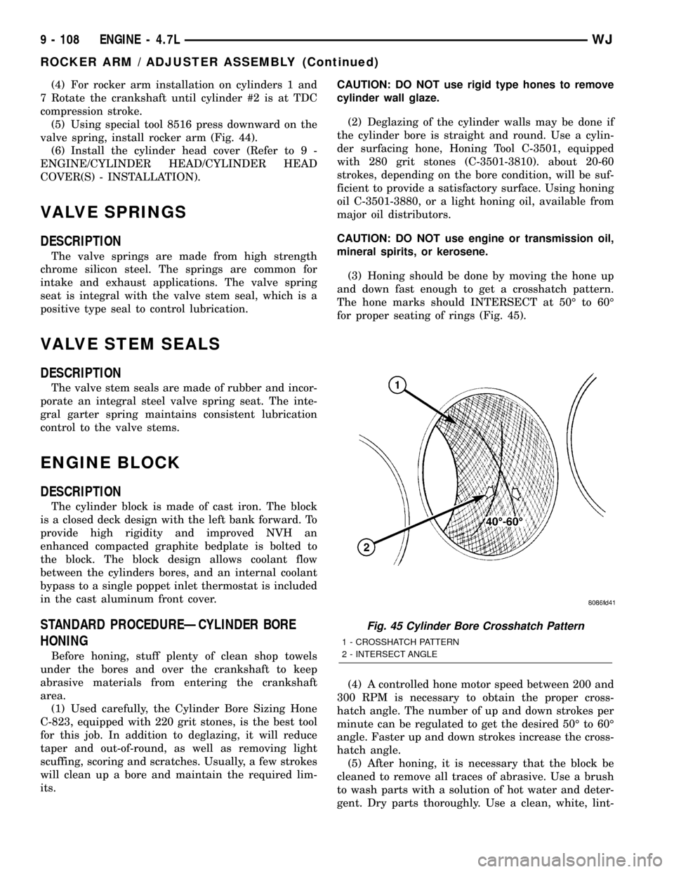
for proper seating of rings (Fig. 45).
(4) A controlled hone motor speed between 200 and
300 RPM is necessary to obtain the proper cross-
hatch angle. The number of up and down strokes per
minute can be regulated to get the desired 50É to 60É
angle. Faster up and down strokes increase the cross-
hatch angle.
(5) After honing, it is necessary that the block be
cleaned to remove all traces of abrasive. Use a brush
to wash parts with a solution of hot water and deter-
gent. Dry parts thoroughly. Use a clean, white, lint-
Fig. 45 Cylinder Bore Crosshatch Pattern
1 - CROSSHATCH PATTERN
2 - INTERSECT ANGLE
9 - 108 ENGINE - 4.7LWJ
ROCKER ARM / ADJUSTER ASSEMBLY (Continued)
Page 1379 of 2199
INTAKE MANIFOLD
DESCRIPTION
The intake manifold is made of a composite mate-
rial and features long runners which maximizes low
end torque. The intake manifold uses single plane
sealing which consist of eight individual press in
place port gaskets to prevent leaks. Eight studs and
two bolts are used to fasten the intake to the head.
DIAGNOSIS AND TESTINGÐINTAKE
MANIFOLD LEAKAGE
An intake manifold air leak is characterized by
lower than normal manifold vacuum. Also, one or
more cylinders may not be functioning.
WARNING: USE EXTREME CAUTION WHEN THE
ENGINE IS OPERATING. DO NOT STAND IN A
DIRECT LINE WITH THE FAN. DO NOT PUT YOUR
HANDS NEAR THE PULLEYS, BELTS OR THE FAN.
DO NOT WEAR LOOSE CLOTHING.
(1) Start the engine.
(2) Spray a small stream of water at the suspected
leak area.
(3) If a change in RPM is observed the area of the
suspected leak has been found.
(4) Repair as required.
REMOVAL
(1) Disconnect negative cable from battery.
(2) Remove air cleaner housing and throttle body
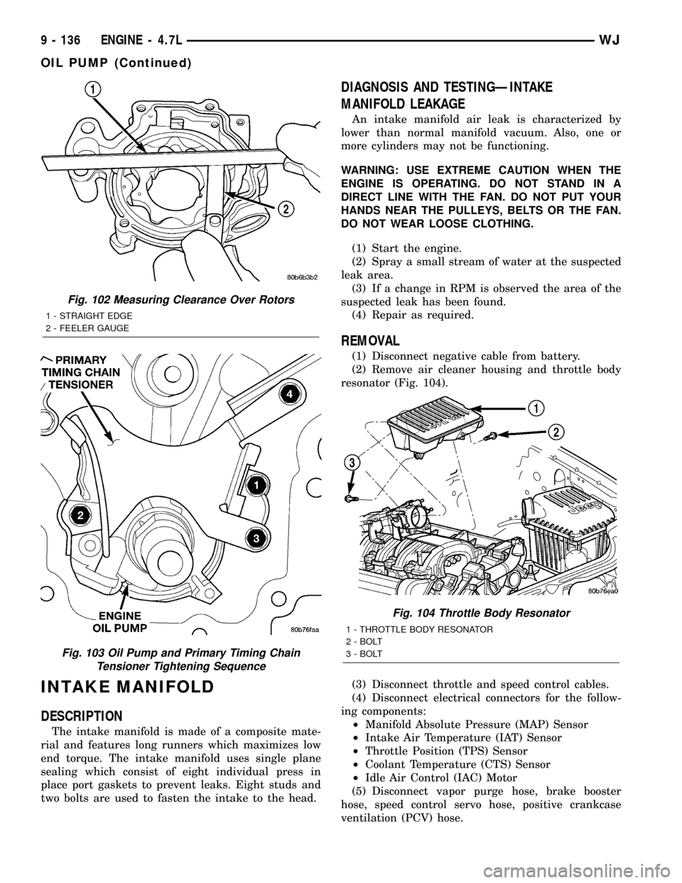
resonator (Fig. 104).
(3) Disconnect throttle and speed control cables.
(4) Disconnect electrical connectors for the follow-
ing components:
²Manifold Absolute Pressure (MAP) Sensor
²Intake Air Temperature (IAT) Sensor
²Throttle Position (TPS) Sensor
²Coolant Temperature (CTS) Sensor
²Idle Air Control (IAC) Motor
(5) Disconnect vapor purge hose, brake booster
hose, speed control servo hose, positive crankcase
ventilation (PCV) hose.
Fig. 102 Measuring Clearance Over Rotors
1 - STRAIGHT EDGE
2 - FEELER GAUGE
Fig. 103 Oil Pump and Primary Timing Chain
Tensioner Tightening Sequence
Fig. 104 Throttle Body Resonator
1 - THROTTLE BODY RESONATOR
2 - BOLT
3 - BOLT
9 - 136 ENGINE - 4.7LWJ
OIL PUMP (Continued)
Page 1381 of 2199

(7) Connect throttle cable and speed control cable
to throttle body.
(8) Install fuel rail (Refer to 14 - FUEL SYSTEM/
FUEL DELIVERY/FUEL RAIL - INSTALLATION).
(9) Install ignition coil towers (Refer to 8 - ELEC-
TRICAL/IGNITION CONTROL/IGNITION COIL -
INSTALLATION).
(10) Install coolant temperature sensor (Refer to 7
- COOLING/ENGINE/ENGINE COOLANT TEMP
SENSOR - INSTALLATION).
(11) Connect electrical connectors for the following
components:
²Manifold Absolute Pressure (MAP) Sensor
²Intake Air Temperature (IAT) Sensor
²Throttle Position (TPS) Sensor
²Coolant Temperature (CTS) Sensor
²Idle Air Control (IAC) Motor
²Ignition coil towers
²Fuel injectors
(12) Install top oil dipstick tube retaining bolt and
ground strap.
(13) Install right side engine lifting stud.
(14) Install generator including electrical connec-
tions (Refer to 8 - ELECTRICAL/CHARGING/GEN-
ERATOR - INSTALLATION).
(15) Connect Vapor purge hose, Brake booster
hose, Speed control servo hose, Positive crankcase
ventilation (PCV) hose.
(16) Install air conditioning compressor including
electrical connections.
(17) Fill cooling system (Refer to 7 - COOLING -
STANDARD PROCEDURE).
(18) Install accessory drive belt (Refer to 7 -
COOLING/ACCESSORY DRIVE/DRIVE BELTS -
INSTALLATION).
(19) Install cowl to hood seal (Refer to 23 - BODY/
WEATHERSTRIP/SEALS/COWL WEATHERSTRIP -
INSTALLATION).
(20) Install air cleaner housing and throttle body
resonator. Tighten resonator bolts 4.5 N´m (40 in.
lbs.).
(21) Connect negative cable to battery.
EXHAUST MANIFOLD - LEFT
DESCRIPTION
The exhaust manifolds are log style with a pat-
ented flow enhancing design to maximize perfor-
mance. The exhaust manifolds are made of high
silicon molybdenum cast iron. A perforated core
graphite exhaust manifold gasket is used to improve
sealing to the cylinder head. The exhaust manifolds
are covered by a three layer laminated heat shield
for thermal protection and noise reduction. The heat
shields are fastened with a torque prevailing nutthat is backed off slightly to allow for the thermal
expansion of the exhaust manifold.
REMOVAL
(1) Disconnect negative cable for battery.
(2) Hoist vehicle.
(3) Disconnect exhaust pipe at manifold.
(4) Lower vehicle.
(5) Remove air cleaner housing and tube.
(6) Remove the front two exhaust heat shield
retaining fasteners. Raise vehicle and remove the
fasteners at rear of heat shield.
(7) Remove heat shield (Fig. 107).
(8) Lower vehicle and remove the upper exhaust
manifold retaining bolts (Fig. 107).
(9) Raise vehicle and remove the lower exhaust
manifold retaining bolts (Fig. 107).
(10) Remove exhaust manifold and gasket (Fig.
107). Manifold is removed from below the engine
compartment.
CLEANING
(1) Clean the exhaust manifold using a suitable
cleaning solvent, then allow to air dry.
(2) Clean all gasket residue from the manifold
mating surface.
INSPECTION
(1) Inspect the exhaust manifold for cracks in the
mating surface and at every mounting bolt hole.
(2) Using a straight edge and a feeler gauge, check
the mating surface for warp and twist.
(3) Inspect the manifold to exhaust pipe mating
surface for cracks, gouges, or other damage that
would prevent sealing.
INSTALLATION
(1) Install exhaust manifold and gasket from below
engine compartment.
(2) Install lower exhaust manifold fasteners (Fig.
107). DO NOT tighten until all fasteners are in
place.
(3) Lower vehicle and install upper exhaust mani-
fold fasteners (Fig. 107). Tighten all manifold bolts
starting at center and working outward to 25 N´m
(18 ft. lbs.).
CAUTION: Over tightening heat shield fasteners,
may cause shield to distort and/or crack.
(4) Install exhaust manifold heat shield (Fig. 107).
Tighten fasteners to 8 N´m (72 in. lbs.), then loosen
45 degrees.
(5) Install air cleaner housing and tube.
(6) Connect exhaust pipe to manifold.
(7) Connect negative cable to battery.
9 - 138 ENGINE - 4.7LWJ
INTAKE MANIFOLD (Continued)
Page 1384 of 2199
INSPECTION
(1) Inspect the exhaust manifold for cracks in the
mating surface and at every mounting bolt hole.
(2) Using a straight edge and a feeler gauge, check
the mating surface for warp and twist.
(3) Inspect the manifold to exhaust pipe mating
surface for cracks, gouges, or other damage that
would prevent sealing.
INSTALLATION
(1) Install exhaust manifold and gasket from below
engine compartment.
(2) Install lower exhaust manifold fasteners. DO
NOT tighten until all fasteners are in place.
(3) Lower vehicle and install upper exhaust mani-
fold fasteners. Tighten all manifold bolts starting at
center and working outward to 25 N´m (18 ft. lbs.).
CAUTION: Over tightening heat shield fasteners,
may cause shield to distort and/or crack.
(4) Install exhaust manifold heat shield. Tighten
fasteners to 8 N´m (72 in. lbs.), then loosen 45
degrees.
(5) Install starter and fasteners.
(6) Connect exhaust pipe to manifold.
(7) Connect heater hoses at engine.
(8) Install fastener attaching A/C accumulator.
(9) Install A/C compressor and fasteners.
(10) Install accessory drive belt (Refer to 7 -
COOLING/ACCESSORY DRIVE/DRIVE BELTS -
INSTALLATION).
(11) Install washer bottle and battery tray assem-
bly.
(12) Install PDC.
(13) Install battery and connect cables.
(14) Fill cooling system (Refer to 7 - COOLING -
STANDARD PROCEDURE).
VALVE TIMING
DESCRIPTION - TIMING DRIVE SYSTEM
The timing drive system has been designed to pro-
vide quiet performance and reliability to support a
non-free wheelingengine. Specifically the intake
valves are non-free wheeling and can be easily dam-
aged with forceful engine rotation if camshaft-to-
crankshaft timing is incorrect. The timing drive
system consists of a primary chain and two second-
ary timing chain drives (Fig. 109).
OPERATION - TIMING DRIVE SYSTEM
The primary timing chain is a single inverted tooth
type. The primary chain drives the large fifty tooth
idler sprocket directly from a 25 tooth crankshaftsprocket. Primary chain motion is controlled by a
pivoting leaf spring tensioner arm and a fixed guide.
The arm and the guide both use nylon plastic wear
faces for low friction and long wear. The primary
chain receives oil splash lubrication from the second-
ary chain drive and oil pump leakage. The idler
sprocket assembly connects the primary and second-
ary chain drives. The idler sprocket assembly con-
sists of two integral thirty tooth sprockets and a fifty
tooth sprocket that is splined to the assembly. The
spline joint is a non ± serviceable press fit anti rattle
type. A spiral ring is installed on the outboard side of
the fifty tooth sprocket to prevent spline disengage-
ment. The idler sprocket assembly spins on a station-
ary idler shaft. The idler shaft is press-fit into the
cylinder block. A large washer on the idler shaft bolt
and the rear flange of the idler shaft are used to con-
trol sprocket thrust movement. Pressurized oil is
routed through the center of the idler shaft to pro-
vide lubrication for the two bushings used in the
idler sprocket assembly.
There are two secondary drive chains, both are
inverted tooth type, one to drive the camshaft in each
SOHC cylinder head. There are no shaft speed
changes in the secondary chain drive system. Each
secondary chain drives a thirty tooth cam sprocket
directly from the thirty tooth sprocket on the idler
sprocket assembly. A fixed chain guide and a hydrau-
lic oil damped tensioner are used to maintain tension
in each secondary chain system. The hydraulic ten-
sioners for the secondary chain systems are fed pres-
surized oil from oil reservoir pockets in the block.
Each tensioner also has a mechanical ratchet system
that limits chain slack if the tensioner piston bleeds
down after engine shut down. The tensioner arms
and guides also utilize nylon wear faces for low fric-
tion and long wear. The secondary timing chains
receive lubrication from a small orifice in the ten-
sioners. This orifice is protected from clogging by a
fine mesh screen which is located on the back of the
hydraulic tensioners.
STANDARD PROCEDURE
STANDARD PROCEDURE - ENGINE TIMING -
VERIFICATION
CAUTION: The 4.7L is a non free-wheeling design
engine. Therefore, correct engine timing is critical.
NOTE: Components referred to as left hand or right
hand are as viewed from the drivers position inside
the vehicle.
WJENGINE - 4.7L 9 - 141
EXHAUST MANIFOLD - RIGHT (Continued)
Page 1437 of 2199
(9) Disconnect speed control cable at throttle body
(if equipped). Refer to Speed Control Cable.
(10) Disconnect automatic transmission cable at
throttle body (if equipped).
(11) Remove cable routing bracket at intake mani-
fold.
(12) Clean dirt/debris from each fuel injector at
intake manifold.
(13) Remove fuel rail mounting nuts/bolts (Fig.
24).
(14) Remove fuel rail by gently rocking until all
fuel injectors have cleared machined holes at intake
manifold.
(15) If fuel injectors are to be removed, refer to
Fuel Injector Removal/Installation.
INSTALLATION
INSTALLATION - 4.7L
(1) If fuel injectors are to be installed, refer to Fuel
Injector Removal/Installation.
(2) Apply a small amount of engine oil to each fuel
injector o-ring. This will help in fuel rail installation.
(3) Position fuel rail/fuel injector assembly to
machined injector openings in cylinder head.
(4) Guide each injector into cylinder head. Be care-
ful not to tear injector o-rings.(5) Pushrightside of fuel rail down until fuel
injectors have bottomed on cylinder head shoulder.
Pushleftfuel rail down until injectors have bot-
tomed on cylinder head shoulder.
(6) Install 4 fuel rail mounting bolts and tighten to
27 N´m (20 ft. lbs.).
(7) Install ignition coils. Refer to Ignition Coil
Removal/Installation.
(8) Connect electrical connectors to throttle body.
(9) Connect electrical connectors to MAP and IAT
sensors.
(10) Connect electrical connectors at all fuel injec-
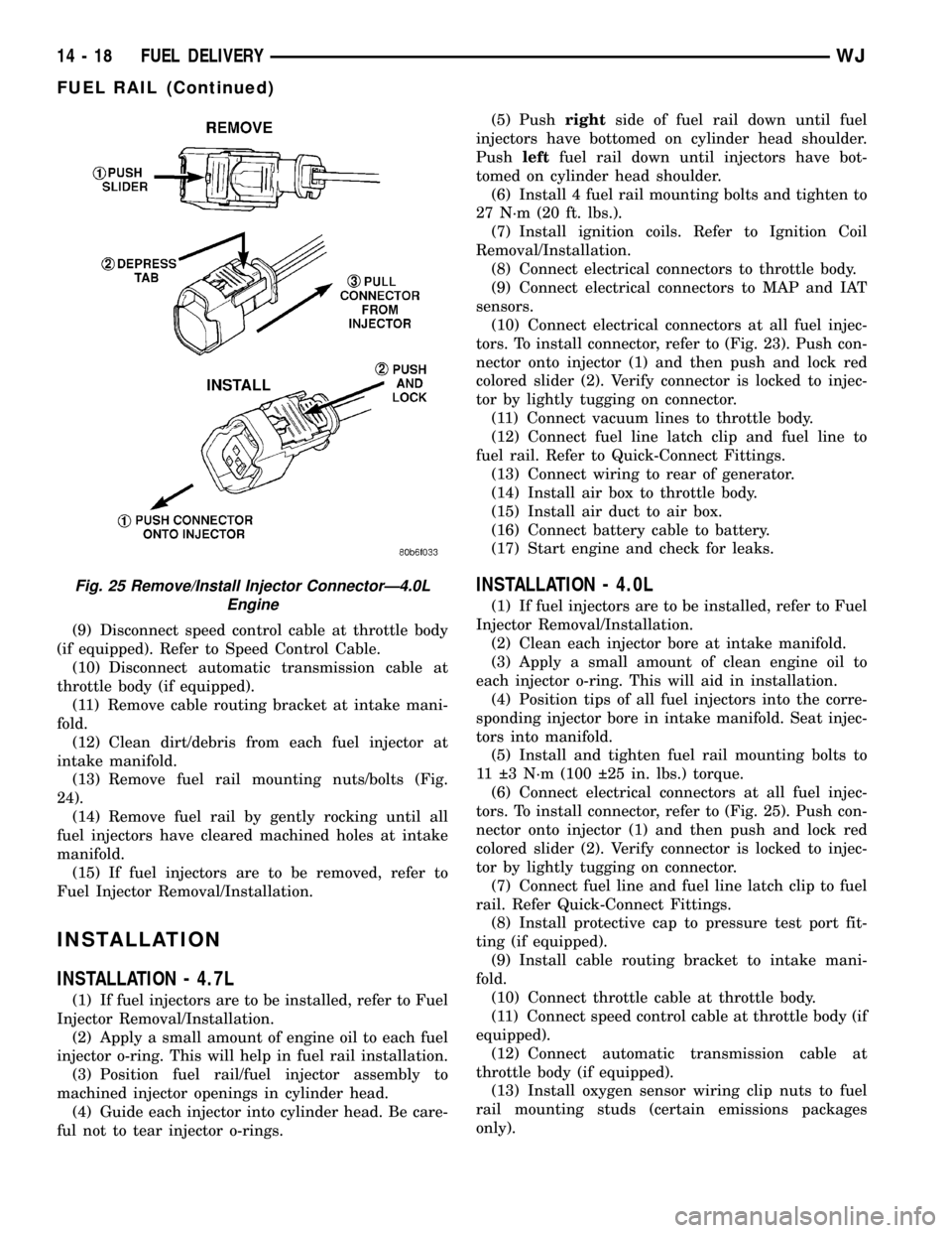
tors. To install connector, refer to (Fig. 23). Push con-
nector onto injector (1) and then push and lock red
colored slider (2). Verify connector is locked to injec-
tor by lightly tugging on connector.
(11) Connect vacuum lines to throttle body.
(12) Connect fuel line latch clip and fuel line to
fuel rail. Refer to Quick-Connect Fittings.
(13) Connect wiring to rear of generator.
(14) Install air box to throttle body.
(15) Install air duct to air box.
(16) Connect battery cable to battery.
(17) Start engine and check for leaks.
INSTALLATION - 4.0L
(1) If fuel injectors are to be installed, refer to Fuel
Injector Removal/Installation.
(2) Clean each injector bore at intake manifold.
(3) Apply a small amount of clean engine oil to
each injector o-ring. This will aid in installation.
(4) Position tips of all fuel injectors into the corre-
sponding injector bore in intake manifold. Seat injec-
tors into manifold.
(5) Install and tighten fuel rail mounting bolts to
11 3 N´m (100 25 in. lbs.) torque.
(6) Connect electrical connectors at all fuel injec-
tors. To install connector, refer to (Fig. 25). Push con-
nector onto injector (1) and then push and lock red
colored slider (2). Verify connector is locked to injec-
tor by lightly tugging on connector.
(7) Connect fuel line and fuel line latch clip to fuel
rail. Refer Quick-Connect Fittings.
(8) Install protective cap to pressure test port fit-
ting (if equipped).
(9) Install cable routing bracket to intake mani-
fold.
(10) Connect throttle cable at throttle body.
(11) Connect speed control cable at throttle body (if
equipped).
(12) Connect automatic transmission cable at
throttle body (if equipped).
(13) Install oxygen sensor wiring clip nuts to fuel
rail mounting studs (certain emissions packages
only).
Fig. 25 Remove/Install Injector ConnectorÐ4.0L
Engine
14 - 18 FUEL DELIVERYWJ
FUEL RAIL (Continued)
Page 1453 of 2199
(8) Inspect system body grounds for loose or dirty
connections. Refer to Group 8, Wiring for ground
locations.
(9) Verify crankcase ventilation (CCV) operation.
Refer to Emission Control System for additional
information.
(10) Inspect all fuel line quick-connect fittings for
damage or leaks.
(11) Verify hose connections to all ports of vacuum
fittings on intake manifold, and for emission system
are tight and not leaking.
(12) Inspect accelerator cable, transmission throt-
tle cable (if equipped) and speed control cable connec-
tions (if equipped). Check their connections to
throttle body linkage for any binding or restrictions.
(13) Verify vacuum booster hose is firmly con-
nected to fitting on intake manifold. Also check con-
nection to brake vacuum booster.(14) Inspect air cleaner inlet and air cleaner ele-
ment for dirt or restrictions.
(15) Inspect radiator grille area, radiator fins and
air conditioning condenser for restrictions.
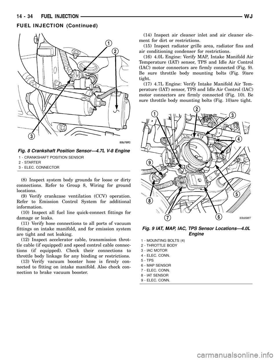
(16) 4.0L Engine: Verify MAP, Intake Manifold Air
Temperature (IAT) sensor, TPS and Idle Air Control
(IAC) motor connectors are firmly connected (Fig. 9).
Be sure throttle body mounting bolts (Fig. 9)are
tight.
(17) 4.7L Engine: Verify Intake Manifold Air Tem-
perature (IAT) sensor, TPS and Idle Air Control (IAC)
motor connectors are firmly connected (Fig. 10). Be
sure throttle body mounting bolts (Fig. 10)are tight.
Fig. 8 Crankshaft Position SensorÐ4.7L V-8 Engine
1 - CRANKSHAFT POSITION SENSOR
2-STARTER
3 - ELEC. CONNECTOR
Fig. 9 IAT, MAP, IAC, TPS Sensor LocationsÐ4.0L
Engine
1 - MOUNTING BOLTS (4)
2 - THROTTLE BODY
3 - IAC MOTOR
4 - ELEC. CONN.
5 - TPS
6 - MAP SENSOR
7 - ELEC. CONN.
8 - IAT SENSOR
9 - ELEC. CONN.
14 - 34 FUEL INJECTIONWJ
FUEL INJECTION (Continued)
Page 1459 of 2199
CRANKSHAFT POSITION
SENSOR
DESCRIPTION
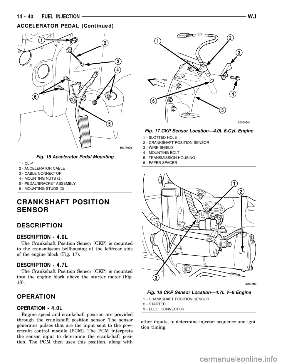
DESCRIPTION - 4.0L
The Crankshaft Position Sensor (CKP) is mounted
to the transmission bellhousing at the left/rear side
of the engine block (Fig. 17).
DESCRIPTION - 4.7L
The Crankshaft Position Sensor (CKP) is mounted
into the engine block above the starter motor (Fig.
18).
OPERATION
OPERATION - 4.0L
Engine speed and crankshaft position are provided
through the crankshaft position sensor. The sensor
generates pulses that are the input sent to the pow-
ertrain control module (PCM). The PCM interprets
the sensor input to determine the crankshaft posi-
tion. The PCM then uses this position, along withother inputs, to determine injector sequence and igni-
tion timing.
Fig. 16 Accelerator Pedal Mounting
1 - CLIP
2 - ACCELERATOR CABLE
3 - CABLE CONNECTOR
4 - MOUNTING NUTS (2)
5 - PEDAL/BRACKET ASSEMBLY
6 - MOUNTING STUDS (2)
Fig. 17 CKP Sensor LocationÐ4.0L 6-Cyl. Engine
1 - SLOTTED HOLE
2 - CRANKSHAFT POSITION SENSOR
3 - WIRE SHIELD
4 - MOUNTING BOLT
5 - TRANSMISSION HOUSING
6 - PAPER SPACER
Fig. 18 CKP Sensor LocationÐ4.7L V±8 Engine
1 - CRANKSHAFT POSITION SENSOR
2-STARTER
3 - ELEC. CONNECTOR
14 - 40 FUEL INJECTIONWJ
ACCELERATOR PEDAL (Continued)