2003 JEEP GRAND CHEROKEE Rear axle
[x] Cancel search: Rear axlePage 1438 of 2199

(14) Install air tube (or duct) at top of throttle
body.
(15) Install fuel tank cap.
(16) Connect negative battery cable to battery.
(17) Start engine and check for fuel leaks.
FUEL TANK
DESCRIPTION
The fuel tank is constructed of a plastic material.
Its main functions are for fuel storage and for place-
ment of the fuel pump module and certain ORVR
components.
OPERATION
All models pass a full 360 degree rollover test
without fuel leakage. To accomplish this, fuel and
vapor flow controls are required for all fuel tank con-
nections.
A fuel tank check valve(s) is mounted into the top
of the fuel tank (or pump module). Refer to Fuel
Tank Check Valve for additional information.
An evaporation control system is connected to the
check valve(s) to reduce emissions of fuel vapors into
the atmosphere. When fuel evaporates from the fuel
tank, vapors pass through vent hoses or tubes to a
charcoal canister where they are temporarily held.
When the engine is running, the vapors are drawn
into the intake manifold. Certain models are also
equipped with a self-diagnosing system using a Leak
Detection Pump (LDP). Refer to Emission Control
System for additional information.
Refer to ORVR for On-Board Refueling Vapor
Recovery system information.
REMOVAL
WARNING: THE FUEL SYSTEM IS UNDER CON-
STANT FUEL PRESSURE EVEN WITH ENGINE OFF.
PRESSURE MUST BE RELEASED BEFORE SERVIC-
ING FUEL TANK.
Two different procedures may be used to drain fuel
tank (through ORVR control valve opening at top of
fuel tank, or using DRB scan tool). The quickest is
draining through ORVR control valve opening at top
of fuel tank (Fig. 26).
As an alternative procedure, the electric fuel pump
may be activated allowing tank to be drained at fuel
rail connection. Refer to DRB scan tool for fuel pump
activation procedures. Before disconnecting fuel line
at fuel rail, release fuel pressure. Refer to the Fuel
System Pressure Release Procedure for procedures.
Attach end of Special Adapter Hose Tool number
6539 at fuel rail disconnection. Position opposite end
of 6539 to an approved gasoline draining station.Activate fuel pump with DRB and drain tank until
empty.
If electric fuel pump is not operating, tankMUST
be drained through ORVR control valve opening at
top of fuel tank (Fig. 26).
(1) Release fuel system pressure. Refer to Fuel
System Pressure Release Procedure.
(2) Disconnect negative battery cable at battery.
(3) Raise and support vehicle.
(4) Remove left rear wheel/tire.
CAUTION: HANDLE EVAP, LDP AND ORVR VAPOR /
VACUUM LINES VERY CAREFULLY. THESE LINES
AND HOSES MUST BE FIRMLY CONNECTED.
CHECK THE VAPOR/VACUUM LINES AT THE LDP,
LDP FILTER, EVAP CANISTER, EVAP CANISTER
PURGE SOLENOID AND ORVR COMPONENTS FOR
DAMAGE OR LEAKS. IF A LEAK IS PRESENT, A
DIAGNOSTIC TROUBLE CODE (DTC) MAY BE SET.
(5) Clean top of fuel tank at ORVR control valve
(Fig. 26) or (Fig. 27).
(6) Press release tab in direction of arrow in (Fig.
27) and remove ORVR control valve lock ring
(counter-clockwise). Lift up ORVR control slightly.
Using an approved gasoline draining station, drain
tank until empty through this opening.
(7) Remove stone shield behind left/rear wheel
(Fig. 28). Drill out plastic rivets for removal.
(8) Remove 3 LDP mounting bolts (Fig. 29).
(9) Remove support bracket brace bolt (Fig. 30).
(10) Loosen, but do not remove 2 support bracket
nuts at frame rail (Fig. 29).
(11) To separate and lower front section of two-
piece support bracket, remove 3 attaching bolts on
bottom of support bracket (Fig. 30). While lowering
support bracket, disconnect LDP wiring clip (Fig. 31).
(12) Remove hose clamp (Fig. 32) and remove fuel
fill hose from fuel fill tube.
(13) Cut and discard tie wrap from axle vent hose
(Fig. 32).
(14) Disconnect fuel vent hose from fuel vent tube
(Fig. 32).
(15) Disconnect ORVR hose elbow (Fig. 33) at top
of EVAP canister.
(16) Place hydraulic jack to bottom of fuel tank.
(17) Remove fuel tank-to-rear bumper fascia clips
(Fig. 34).
(18) Remove fuel tank heat shield mounting bolts
(Fig. 35).
CAUTION: To protect fuel tank from exhaust heat,
shield must re-installed after tank installation.
WARNING: PLACE SHOP TOWEL AROUND FUEL
LINES TO CATCH ANY EXCESS FUEL.
WJFUEL DELIVERY 14 - 19
FUEL RAIL (Continued)
Page 1439 of 2199
(19) Disconnect fuel return line at fuel filter/fuel
pressure regulator (Fig. 36). Refer to Quick-Connect
Fittings for procedures.
(20) Disconnect fuel pressure line at fuel filter/fuel
pressure regulator (Fig. 36). Refer to Quick-Connect
Fittings for procedures.
(21) Disconnect EVAP canister vent line near front
of tank (Fig. 36).
(22) Disconnect fuel pump module electrical con-
nector (pigtail harness) near front of tank (Fig. 36).
Harness connector is clipped to body.
(23) Remove left / front tank support bracket bolt
at frame (Fig. 37).
(24)WITHOUT TRAILER HITCH:Remove tank-
to-frame mounting bolts (Fig. 39). Remove rear tank
support bracket bolts at frame (Fig. 38). Carefully
lower tank until clear of vehicle. Place tank on floor.
(25)WITH TRAILER HITCH:Remove tank /
hitch mounting bolts (Fig. 40). Carefully lower tank
until clear of vehicle. Place tank on floor.
(26) If necessary, separate skid plate from fuel
tank by removing 2 fuel tank strap nuts (Fig. 39) and
remove 2 tank straps.
(27) If fuel pump module removal is necessary,
refer to Fuel Pump Module Removal/Installation.
(28) If hoses are to be removed at fuel tank end,
note painted alignment (indexing) markings on
hoses, and molded indexing tangs on tank before
removal. Remove hoses.
(29) If necessary, remove 3 fuel filler tube assem-
bly mounting bolts (Fig. 41) and remove fuel filler
tube.
INSTALLATION
CAUTION: HANDLE EVAP, LDP AND ORVR VAPOR /
VACUUM LINES VERY CAREFULLY. THESE LINES
AND HOSES MUST BE FIRMLY CONNECTED.
CHECK THE VAPOR/VACUUM LINES AT THE LDP,
LDP FILTER, EVAP CANISTER, EVAP CANISTER
PURGE SOLENOID AND ORVR COMPONENTS FOR
DAMAGE OR LEAKS. IF A LEAK IS PRESENT, A
DIAGNOSTIC TROUBLE CODE (DTC) MAY BE SET.
(1) If necessary, position fuel filler tube assembly
to body. Install 3 bolts and tighten to 2 N´m (15 in.
lbs.) torque.
(2) If necessary, connect quick-connect fittings to
fuel pump module.
(3) If fuel pump module is being installed, refer to
Fuel Pump Module Removal/Installation.
(4) Install fuel fill/vent hoses to tank fittings. To
prevent hoses from kinking, rotate each hose until
painted indexing mark on hose is aligned to molded
indexing tang on tank.
(5) Install hose clamps to hoses. Refer to Torque
Specifications.(6) If necessary, position fuel tank into skid plate.
Install 2 tank straps and 2 strap nuts (Fig. 39). Refer
to Torque Specifications.
(7) Position fuel tank / skid plate assembly to
hydraulic jack.
(8) Raise tank into position to frame.
(9)WITH TRAILER HITCH:Position trailer
hitch and tow hooks (Fig. 40) to bottom of fuel tank.
Install bolts and nuts loosely.
(10)WITHOUT TRAILER HITCH:Install 2 rear
tank support brackets and bolts (Fig. 38). Install
tank-to-frame bolts. Do not tighten bolts / nuts at
this time.
(11) Install 1 left / front tank support bracket and
bolts / nuts (Fig. 37). Do not tighten bolts / nuts at
this time.
(12) Be sure fuel tank is properly aligned to frame
and body. Tighten all tank, tow hook and trailer
hitch bolts / nuts except for 3 support brackets.
Tighten all 3 (2 rear and 1 left / front) support
bracket bolts / nuts last. Refer to Torque Specifica-
tions.
(13)
(14) Connect fuel pump module pigtail harness
electrical connector near front of tank.
(15) Connect both fuel lines to fuel filter/fuel pres-
sure regulator. Refer to Quick-Connect Fittings for
procedures.
(16) Connect EVAP hose near front of tank.
(17) Position rear axle vent hose and install new
tie strap (Fig. 32).
(18) Install heat shield nuts / bolts (Fig. 35). Refer
to Torque Specifications.
(19) Connect ORVR hose elbow (Fig. 33) to top of
EVAP canister.
(20) Connect fuel vent hose to fuel vent tube (Fig.
32).
(21) Install fuel fill hose and clamp to fuel fill tube
(Fig. 32).
(22) Install 3 LDP mounting bolts (Fig. 29).
(23) While raising support bracket, connect LDP
wiring clip (Fig. 31). Install front section of two-piece
support bracket to rear section with 3 attaching bolts
located on bottom of support bracket (Fig. 30).
(24) Install support bracket brace bolt (Fig. 30).
(25) Tighten 2 support bracket nuts at frame rail
(Fig. 29).
(26) Install fuel tank-to-rear bumper fascia clips
(Fig. 34).
(27) Using new plastic rivets, install stone shield
behind left/rear wheel (Fig. 28).
(28) Install left rear wheel/tire.
(29) Lower vehicle and connect negative battery
cable to battery.
(30) Fill tank with fuel and check for leaks.
14 - 20 FUEL DELIVERYWJ
FUEL TANK (Continued)
Page 1443 of 2199
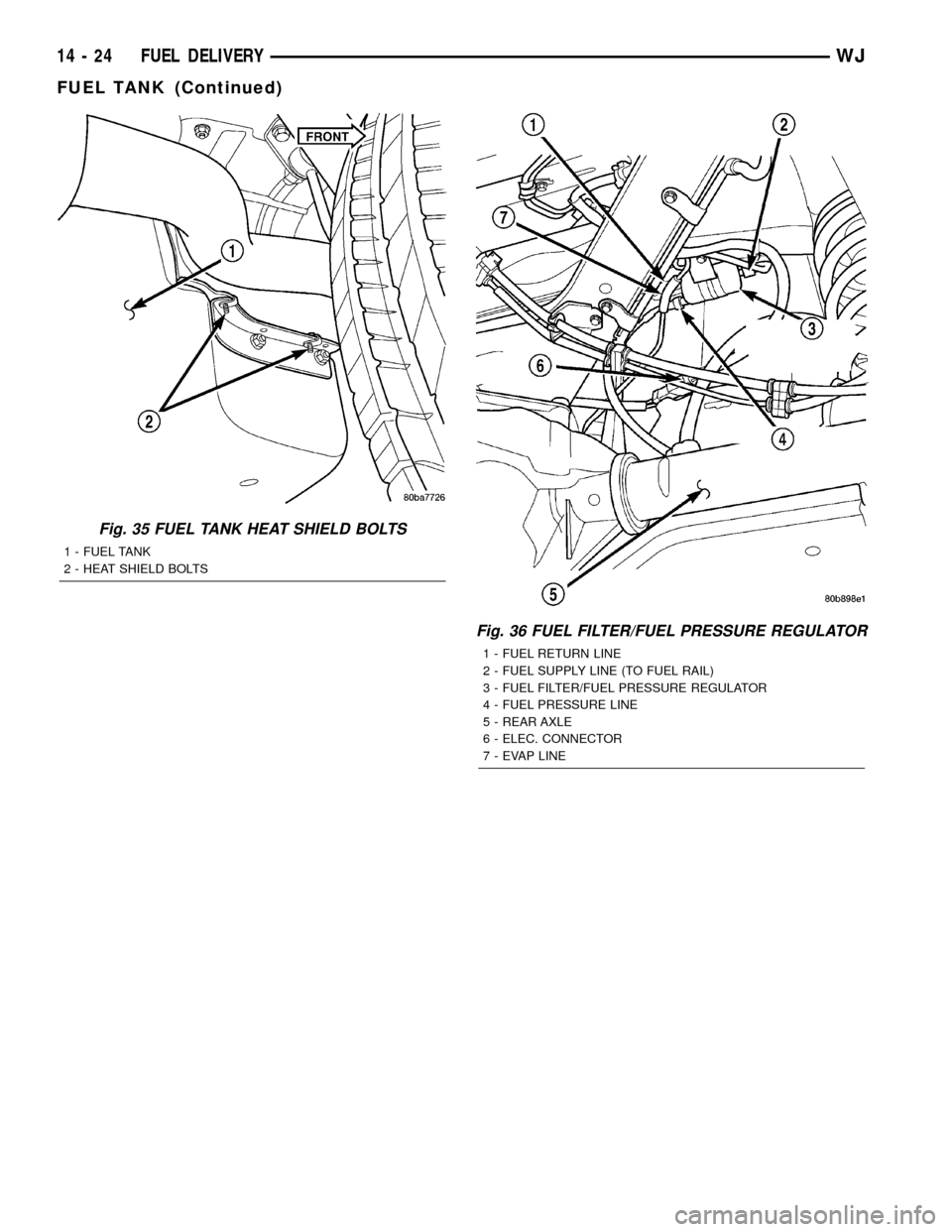
Fig. 35 FUEL TANK HEAT SHIELD BOLTS
1 - FUEL TANK
2 - HEAT SHIELD BOLTS
Fig. 36 FUEL FILTER/FUEL PRESSURE REGULATOR
1 - FUEL RETURN LINE
2 - FUEL SUPPLY LINE (TO FUEL RAIL)
3 - FUEL FILTER/FUEL PRESSURE REGULATOR
4 - FUEL PRESSURE LINE
5 - REAR AXLE
6 - ELEC. CONNECTOR
7 - EVAP LINE
14 - 24 FUEL DELIVERYWJ
FUEL TANK (Continued)
Page 1457 of 2199
(23) Inspect for pinched or leaking fuel tubes/lines.
Inspect for pinched, cracked or leaking fuel hoses.
(24) Inspect for exhaust system restrictions such
as pinched exhaust pipes, collapsed muffler or
plugged catalytic convertor.
(25) If equipped with automatic transmission, ver-
ify electrical harness is firmly connected to park/neu-
tral switch and to transmission components.
(26) Verify fuel pump module pigtail harness elec-
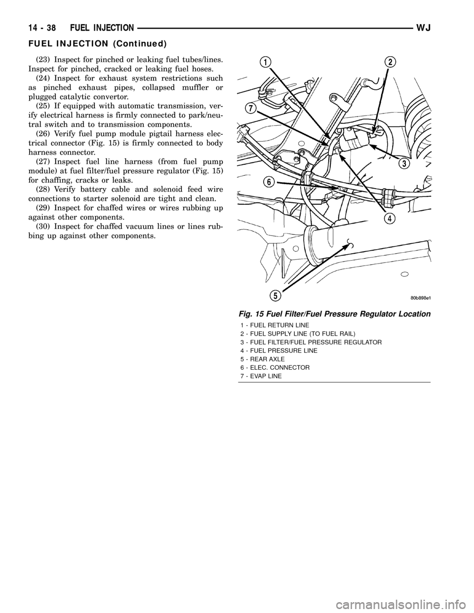
trical connector (Fig. 15) is firmly connected to body
harness connector.
(27) Inspect fuel line harness (from fuel pump
module) at fuel filter/fuel pressure regulator (Fig. 15)
for chaffing, cracks or leaks.
(28) Verify battery cable and solenoid feed wire
connections to starter solenoid are tight and clean.
(29) Inspect for chaffed wires or wires rubbing up
against other components.
(30) Inspect for chaffed vacuum lines or lines rub-
bing up against other components.
Fig. 15 Fuel Filter/Fuel Pressure Regulator Location
1 - FUEL RETURN LINE
2 - FUEL SUPPLY LINE (TO FUEL RAIL)
3 - FUEL FILTER/FUEL PRESSURE REGULATOR
4 - FUEL PRESSURE LINE
5 - REAR AXLE
6 - ELEC. CONNECTOR
7 - EVAP LINE
14 - 38 FUEL INJECTIONWJ
FUEL INJECTION (Continued)
Page 1536 of 2199
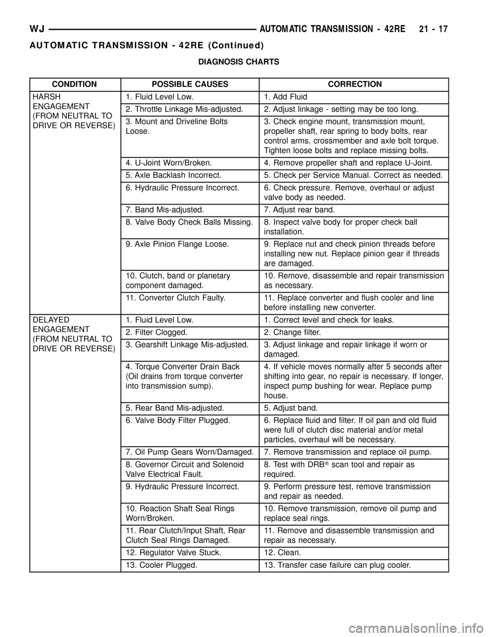
DIAGNOSIS CHARTS
CONDITION POSSIBLE CAUSES CORRECTION
HARSH
ENGAGEMENT
(FROM NEUTRAL TO
DRIVE OR REVERSE)1. Fluid Level Low. 1. Add Fluid
2. Throttle Linkage Mis-adjusted. 2. Adjust linkage - setting may be too long.
3. Mount and Driveline Bolts
Loose.3. Check engine mount, transmission mount,
propeller shaft, rear spring to body bolts, rear
control arms, crossmember and axle bolt torque.
Tighten loose bolts and replace missing bolts.
4. U-Joint Worn/Broken. 4. Remove propeller shaft and replace U-Joint.
5. Axle Backlash Incorrect. 5. Check per Service Manual. Correct as needed.
6. Hydraulic Pressure Incorrect. 6. Check pressure. Remove, overhaul or adjust
valve body as needed.
7. Band Mis-adjusted. 7. Adjust rear band.
8. Valve Body Check Balls Missing. 8. Inspect valve body for proper check ball
installation.
9. Axle Pinion Flange Loose. 9. Replace nut and check pinion threads before
installing new nut. Replace pinion gear if threads
are damaged.
10. Clutch, band or planetary
component damaged.10. Remove, disassemble and repair transmission
as necessary.
11. Converter Clutch Faulty. 11. Replace converter and flush cooler and line
before installing new converter.
DELAYED
ENGAGEMENT
(FROM NEUTRAL TO
DRIVE OR REVERSE)1. Fluid Level Low. 1. Correct level and check for leaks.
2. Filter Clogged. 2. Change filter.
3. Gearshift Linkage Mis-adjusted. 3. Adjust linkage and repair linkage if worn or
damaged.
4. Torque Converter Drain Back
(Oil drains from torque converter
into transmission sump).4. If vehicle moves normally after 5 seconds after
shifting into gear, no repair is necessary. If longer,
inspect pump bushing for wear. Replace pump
house.
5. Rear Band Mis-adjusted. 5. Adjust band.
6. Valve Body Filter Plugged. 6. Replace fluid and filter. If oil pan and old fluid
were full of clutch disc material and/or metal
particles, overhaul will be necessary.
7. Oil Pump Gears Worn/Damaged. 7. Remove transmission and replace oil pump.
8. Governor Circuit and Solenoid
Valve Electrical Fault.8. Test with DRBTscan tool and repair as
required.
9. Hydraulic Pressure Incorrect. 9. Perform pressure test, remove transmission
and repair as needed.
10. Reaction Shaft Seal Rings
Worn/Broken.10. Remove transmission, remove oil pump and
replace seal rings.
11. Rear Clutch/Input Shaft, Rear
Clutch Seal Rings Damaged.11. Remove and disassemble transmission and
repair as necessary.
12. Regulator Valve Stuck. 12. Clean.
13. Cooler Plugged. 13. Transfer case failure can plug cooler.
WJAUTOMATIC TRANSMISSION - 42RE 21 - 17
AUTOMATIC TRANSMISSION - 42RE (Continued)
Page 1537 of 2199
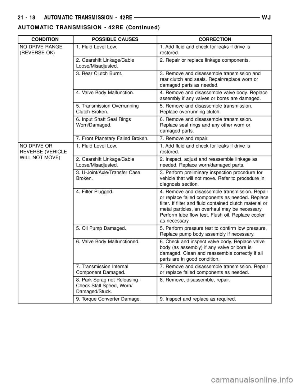
CONDITION POSSIBLE CAUSES CORRECTION
NO DRIVE RANGE
(REVERSE OK)1. Fluid Level Low. 1. Add fluid and check for leaks if drive is
restored.
2. Gearshift Linkage/Cable
Loose/Misadjusted.2. Repair or replace linkage components.
3. Rear Clutch Burnt. 3. Remove and disassemble transmission and
rear clutch and seals. Repair/replace worn or
damaged parts as needed.
4. Valve Body Malfunction. 4. Remove and disassemble valve body. Replace
assembly if any valves or bores are damaged.
5. Transmission Overrunning
Clutch Broken.5. Remove and disassemble transmission.
Replace overrunning clutch.
6. Input Shaft Seal Rings
Worn/Damaged.6. Remove and disassemble transmission.
Replace seal rings and any other worn or
damaged parts.
7. Front Planetary Failed Broken. 7. Remove and repair.
NO DRIVE OR
REVERSE (VEHICLE
WILL NOT MOVE)1. Fluid Level Low. 1. Add fluid and check for leaks if drive is
restored.
2. Gearshift Linkage/Cable
Loose/Misadjusted.2. Inspect, adjust and reassemble linkage as
needed. Replace worn/damaged parts.
3. U-Joint/Axle/Transfer Case
Broken.3. Perform preliminary inspection procedure for
vehicle that will not move. Refer to procedure in
diagnosis section.
4. Filter Plugged. 4. Remove and disassemble transmission. Repair
or replace failed components as needed. Replace
filter. If filter and fluid contained clutch material or
metal particles, an overhaul may be necessary.
Perform lube flow test. Flush oil. Replace cooler
as necessary.
5. Oil Pump Damaged. 5. Perform pressure test to confirm low pressure.
Replace pump body assembly if necessary.
6. Valve Body Malfunctioned. 6. Check and inspect valve body. Replace valve
body (as assembly) if any valve or bore is
damaged. Clean and reassemble correctly if all
parts are in good condition.
7. Transmission Internal
Component Damaged.7. Remove and disassemble transmission. Repair
or replace failed components as needed.
8. Park Sprag not Releasing -
Check Stall Speed, Worn/
Damaged/Stuck.8. Remove, disassemble, repair.
9. Torque Converter Damage. 9. Inspect and replace as required.
21 - 18 AUTOMATIC TRANSMISSION - 42REWJ
AUTOMATIC TRANSMISSION - 42RE (Continued)
Page 1588 of 2199
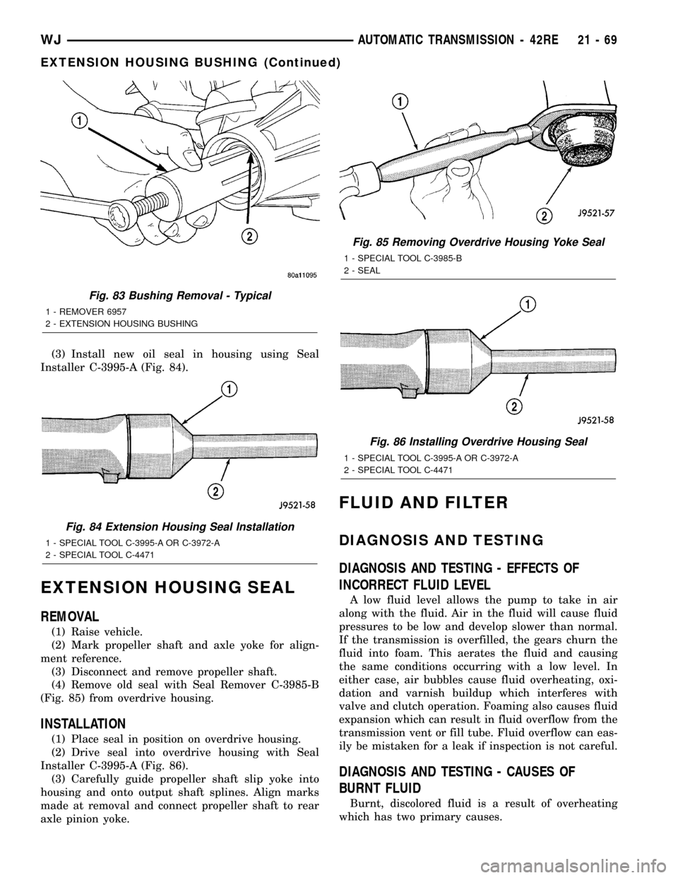
(3) Install new oil seal in housing using Seal
Installer C-3995-A (Fig. 84).
EXTENSION HOUSING SEAL
REMOVAL
(1) Raise vehicle.
(2) Mark propeller shaft and axle yoke for align-
ment reference.
(3) Disconnect and remove propeller shaft.
(4) Remove old seal with Seal Remover C-3985-B
(Fig. 85) from overdrive housing.
INSTALLATION
(1) Place seal in position on overdrive housing.
(2) Drive seal into overdrive housing with Seal
Installer C-3995-A (Fig. 86).
(3) Carefully guide propeller shaft slip yoke into
housing and onto output shaft splines. Align marks
made at removal and connect propeller shaft to rear
axle pinion yoke.
FLUID AND FILTER
DIAGNOSIS AND TESTING
DIAGNOSIS AND TESTING - EFFECTS OF
INCORRECT FLUID LEVEL
A low fluid level allows the pump to take in air
along with the fluid. Air in the fluid will cause fluid
pressures to be low and develop slower than normal.
If the transmission is overfilled, the gears churn the
fluid into foam. This aerates the fluid and causing
the same conditions occurring with a low level. In
either case, air bubbles cause fluid overheating, oxi-
dation and varnish buildup which interferes with
valve and clutch operation. Foaming also causes fluid
expansion which can result in fluid overflow from the
transmission vent or fill tube. Fluid overflow can eas-
ily be mistaken for a leak if inspection is not careful.
DIAGNOSIS AND TESTING - CAUSES OF
BURNT FLUID
Burnt, discolored fluid is a result of overheating
which has two primary causes.
Fig. 83 Bushing Removal - Typical
1 - REMOVER 6957
2 - EXTENSION HOUSING BUSHING
Fig. 84 Extension Housing Seal Installation
1 - SPECIAL TOOL C-3995-A OR C-3972-A
2 - SPECIAL TOOL C-4471
Fig. 85 Removing Overdrive Housing Yoke Seal
1 - SPECIAL TOOL C-3985-B
2 - SEAL
Fig. 86 Installing Overdrive Housing Seal
1 - SPECIAL TOOL C-3995-A OR C-3972-A
2 - SPECIAL TOOL C-4471
WJAUTOMATIC TRANSMISSION - 42RE 21 - 69
EXTENSION HOUSING BUSHING (Continued)
Page 1604 of 2199
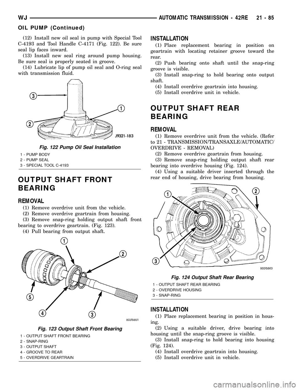
(12) Install new oil seal in pump with Special Tool
C-4193 and Tool Handle C-4171 (Fig. 122). Be sure
seal lip faces inward.
(13) Install new seal ring around pump housing.
Be sure seal is properly seated in groove.
(14) Lubricate lip of pump oil seal and O-ring seal
with transmission fluid.
OUTPUT SHAFT FRONT
BEARING
REMOVAL
(1) Remove overdrive unit from the vehicle.
(2) Remove overdrive geartrain from housing.
(3) Remove snap-ring holding output shaft front
bearing to overdrive geartrain. (Fig. 123).
(4) Pull bearing from output shaft.
INSTALLATION
(1) Place replacement bearing in position on
geartrain with locating retainer groove toward the
rear.
(2) Push bearing onto shaft until the snap-ring
groove is visible.
(3) Install snap-ring to hold bearing onto output
shaft.
(4) Install overdrive geartrain into housing.
(5) Install overdrive unit in vehicle.
OUTPUT SHAFT REAR
BEARING
REMOVAL
(1) Remove overdrive unit from the vehicle. (Refer
to 21 - TRANSMISSION/TRANSAXLE/AUTOMATIC/
OVERDRIVE - REMOVAL)
(2) Remove overdrive geartrain from housing.
(3) Remove snap-ring holding output shaft rear
bearing into overdrive housing (Fig. 124).
(4) Using a suitable driver inserted through the
rear end of housing, drive bearing from housing.
INSTALLATION
(1) Place replacement bearing in position in hous-
ing.
(2) Using a suitable driver, drive bearing into
housing until the snap-ring groove is visible.
(3) Install snap-ring to hold bearing into housing
(Fig. 124).
(4) Install overdrive geartrain into housing.
(5) Install overdrive unit in vehicle.
Fig. 122 Pump Oil Seal Installation
1 - PUMP BODY
2 - PUMP SEAL
3 - SPECIAL TOOL C-4193
Fig. 123 Output Shaft Front Bearing
1 - OUTPUT SHAFT FRONT BEARING
2 - SNAP-RING
3 - OUTPUT SHAFT
4 - GROOVE TO REAR
5 - OVERDRIVE GEARTRAIN
Fig. 124 Output Shaft Rear Bearing
1 - OUTPUT SHAFT REAR BEARING
2 - OVERDRIVE HOUSING
3 - SNAP-RING
WJAUTOMATIC TRANSMISSION - 42RE 21 - 85
OIL PUMP (Continued)