2003 JEEP GRAND CHEROKEE Rear door
[x] Cancel search: Rear doorPage 1639 of 2199
INSPECTION
Replace the clutch discs if warped, worn, scored,
burned/charred, the lugs are damaged, or if the fac-
ing is flaking off. Replace the top and bottom pres-
sure plates if scored, warped, or cracked. Be sure the
driving lugs on the pressure and clutch plates are
also in good condition. The lugs must not be bent,
cracked or damaged in any way.
Replace the piston spring and wave spring if either
part is distorted, warped or broken.
Check the lug grooves in the clutch retainer. The
clutch and pressure plates should slide freely in the
slots. Replace the retainer if the grooves are worn or
damaged. Also check action of the check balls in the
retainer and piston. Each check ball must move
freely and not stick.
Replace the retainer bushing if worn, scored, or
doubt exists about bushing condition.
Inspect the piston and retainer seal surfaces for
nicks or scratches. Minor scratches can be removed
with crocus cloth. However, replace the piston and/or
retainer if the seal surfaces are seriously scored.
Check condition of the fiber thrust washer and
metal output shaft thrust washer. Replace either
washer if worn or damaged.
Check condition of the seal rings on the input shaft
and clutch retainer hub. Replace the seal rings only
if worn, distorted, or damaged. The input shaft front
seal ring is teflon with chamfered ends. The rear ring
is metal with interlocking ends.
Check the input shaft for wear, or damage. Replace
the shaft if worn, scored or damaged in any way.
ASSEMBLY
(1) Soak clutch discs in transmission fluid while
assembling other clutch parts.
(2) Install new seal rings on clutch retainer hub
and input shaft, if necessary, (Fig. 227) and (Fig.
228).
(a) Be sure clutch hub seal ring is fully seated in
groove and is not twisted.
(3) Lubricate splined end of input shaft and clutch
retainer with transmission fluid. Then press input
shaft into retainer (Fig. 229). Use a suitably sized
press tool to support retainer as close to input shaft
as possible.
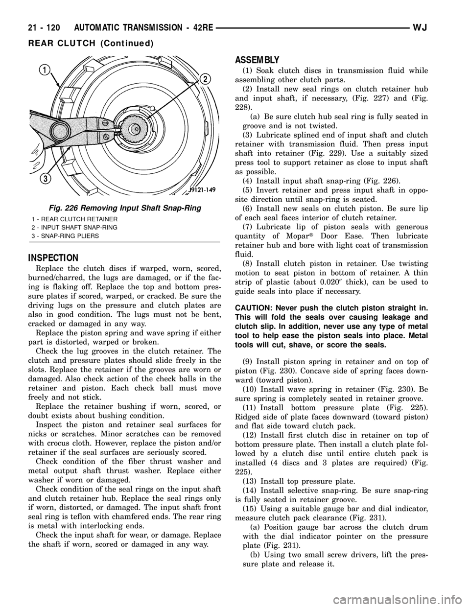
(4) Install input shaft snap-ring (Fig. 226).
(5) Invert retainer and press input shaft in oppo-
site direction until snap-ring is seated.
(6) Install new seals on clutch piston. Be sure lip
of each seal faces interior of clutch retainer.
(7) Lubricate lip of piston seals with generous
quantity of MopartDoor Ease. Then lubricate
retainer hub and bore with light coat of transmission
fluid.
(8) Install clutch piston in retainer. Use twisting
motion to seat piston in bottom of retainer. A thin
strip of plastic (about 0.0209thick), can be used to
guide seals into place if necessary.
CAUTION: Never push the clutch piston straight in.
This will fold the seals over causing leakage and
clutch slip. In addition, never use any type of metal
tool to help ease the piston seals into place. Metal
tools will cut, shave, or score the seals.
(9) Install piston spring in retainer and on top of
piston (Fig. 230). Concave side of spring faces down-
ward (toward piston).
(10) Install wave spring in retainer (Fig. 230). Be
sure spring is completely seated in retainer groove.
(11) Install bottom pressure plate (Fig. 225).
Ridged side of plate faces downward (toward piston)
and flat side toward clutch pack.
(12) Install first clutch disc in retainer on top of
bottom pressure plate. Then install a clutch plate fol-
lowed by a clutch disc until entire clutch pack is
installed (4 discs and 3 plates are required) (Fig.
225).
(13) Install top pressure plate.
(14) Install selective snap-ring. Be sure snap-ring
is fully seated in retainer groove.
(15) Using a suitable gauge bar and dial indicator,
measure clutch pack clearance (Fig. 231).
(a) Position gauge bar across the clutch drum
with the dial indicator pointer on the pressure
plate (Fig. 231).
(b) Using two small screw drivers, lift the pres-
sure plate and release it.
Fig. 226 Removing Input Shaft Snap-Ring
1 - REAR CLUTCH RETAINER
2 - INPUT SHAFT SNAP-RING
3 - SNAP-RING PLIERS
21 - 120 AUTOMATIC TRANSMISSION - 42REWJ
REAR CLUTCH (Continued)
Page 1874 of 2199
BODY
TABLE OF CONTENTS
page page
BODY
DIAGNOSIS AND TESTING
WATER LEAKS........................1
WIND NOISE..........................2
STANDARD PROCEDURE
STANDARD PROCEDURE - BODY
LUBRICATION.........................2
STANDARD PROCEDURE - DRILLING AND
WELDING............................3
SPECIFICATIONS
BODY LUBRICANTS....................3
SPECIFICATIONS - TORQUE.............4
SPECIAL TOOLS
BODY...............................4DECKLID/HATCH/LIFTGATE/TAILGATE........5
DOOR - FRONT.........................11
DOORS - REAR.........................19
EXTERIOR.............................25
HOOD.................................33
INSTRUMENT PANEL SYSTEM.............36
INTERIOR..............................69
PAINT.................................81
SEATS................................83
STATIONARY GLASS.....................93
SUNROOF.............................96
WEATHERSTRIP/SEALS..................105
BODY STRUCTURE.....................112
BODY
DIAGNOSIS AND TESTING
WATER LEAKS
Water leaks can be caused by poor sealing,
improper body component alignment, body seam
porosity, missing plugs, or blocked drain holes. Cen-
trifugal and gravitational force can cause water to
drip from a location away from the actual leak point,
making leak detection difficult. All body sealing
points should be water tight in normal wet-driving
conditions. Water flowing downward from the front of
the vehicle should not enter the passenger or luggage
compartment. Moving sealing surfaces will not
always seal water tight under all conditions. At
times, side glass or door seals will allow water to
enter the passenger compartment during high pres-
sure washing or hard driving rain (severe) condi-
tions. Overcompensating on door or glass
adjustments to stop a water leak that occurs under
severe conditions can cause premature seal wear and
excessive closing or latching effort. After completing
a repair, water test vehicle to verify leak has stopped
before returning vehicle to use.
VISUAL INSPECTION BEFORE WATER LEAK TESTS
Verify that floor and body plugs are in place, body
drains are clear, and body components are properly
aligned and sealed. If component alignment or seal-
ing is necessary, refer to the appropriate section of
this group for proper procedures.
WATER LEAK TESTS
WARNING: DO NOT USE ELECTRIC SHOP LIGHTS
OR TOOLS IN WATER TEST AREA. PERSONAL
INJURY CAN RESULT.
When the conditions causing a water leak have
been determined, simulate the conditions as closely
as possible.
²If a leak occurs with the vehicle parked in a
steady light rain, flood the leak area with an open-
ended garden hose.
²If a leak occurs while driving at highway speeds
in a steady rain, test the leak area with a reasonable
velocity stream or fan spray of water. Direct the
spray in a direction comparable to actual conditions.
²If a leak occurs when the vehicle is parked on an
incline, hoist the end or side of the vehicle to simu-
late this condition. This method can be used when
the leak occurs when the vehicle accelerates, stops or
turns. If the leak occurs on acceleration, hoist the
front of the vehicle. If the leak occurs when braking,
hoist the back of the vehicle. If the leak occurs on left
turns, hoist the left side of the vehicle. If the leak
occurs on right turns, hoist the right side of the vehi-
cle. For hoisting recommendations refer to Group 0,
Lubrication and Maintenance, General Information
section.
WATER LEAK DETECTION
To detect a water leak point-of-entry, do a water
test and watch for water tracks or droplets forming
on the inside of the vehicle. If necessary, remove inte-
rior trim covers or panels to gain visual access to the
WJBODY 23 - 1
Page 1877 of 2199
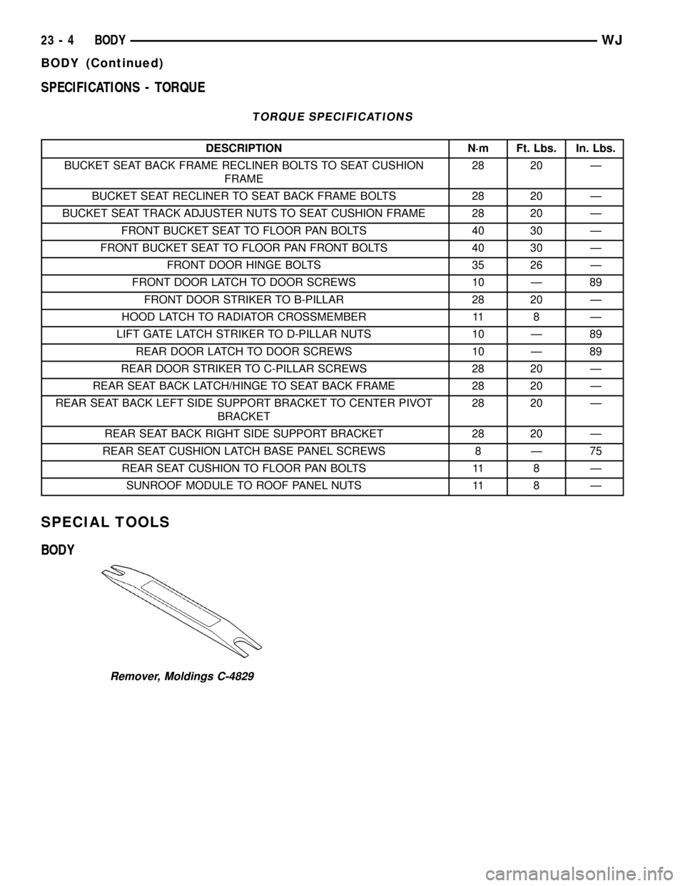
SPECIFICATIONS - TORQUE
TORQUE SPECIFICATIONS
DESCRIPTION N´m Ft. Lbs. In. Lbs.
BUCKET SEAT BACK FRAME RECLINER BOLTS TO SEAT CUSHION
FRAME28 20 Ð
BUCKET SEAT RECLINER TO SEAT BACK FRAME BOLTS 28 20 Ð
BUCKET SEAT TRACK ADJUSTER NUTS TO SEAT CUSHION FRAME 28 20 Ð
FRONT BUCKET SEAT TO FLOOR PAN BOLTS 40 30 Ð
FRONT BUCKET SEAT TO FLOOR PAN FRONT BOLTS 40 30 Ð
FRONT DOOR HINGE BOLTS 35 26 Ð
FRONT DOOR LATCH TO DOOR SCREWS 10 Ð 89
FRONT DOOR STRIKER TO B-PILLAR 28 20 Ð
HOOD LATCH TO RADIATOR CROSSMEMBER 11 8 Ð
LIFT GATE LATCH STRIKER TO D-PILLAR NUTS 10 Ð 89
REAR DOOR LATCH TO DOOR SCREWS 10 Ð 89
REAR DOOR STRIKER TO C-PILLAR SCREWS 28 20 Ð
REAR SEAT BACK LATCH/HINGE TO SEAT BACK FRAME 28 20 Ð
REAR SEAT BACK LEFT SIDE SUPPORT BRACKET TO CENTER PIVOT
BRACKET28 20 Ð
REAR SEAT BACK RIGHT SIDE SUPPORT BRACKET 28 20 Ð
REAR SEAT CUSHION LATCH BASE PANEL SCREWS 8 Ð 75
REAR SEAT CUSHION TO FLOOR PAN BOLTS 11 8 Ð
SUNROOF MODULE TO ROOF PANEL NUTS 11 8 Ð
SPECIAL TOOLS
BODY
Remover, Moldings C-4829
23 - 4 BODYWJ
BODY (Continued)
Page 1886 of 2199
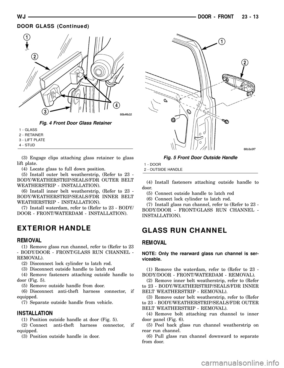
(3) Engage clips attaching glass retainer to glass
lift plate.
(4) Locate glass to full down position.
(5) Install outer belt weatherstrip, (Refer to 23 -
BODY/WEATHERSTRIP/SEALS/FDR OUTER BELT
WEATHERSTRIP - INSTALLATION).
(6) Install inner belt weatherstrip, (Refer to 23 -
BODY/WEATHERSTRIP/SEALS/FDR INNER BELT
WEATHERSTRIP - INSTALLATION).
(7) Install waterdam, refer to (Refer to 23 - BODY/
DOOR - FRONT/WATERDAM - INSTALLATION).
EXTERIOR HANDLE
REMOVAL
(1) Remove glass run channel, refer to (Refer to 23
- BODY/DOOR - FRONT/GLASS RUN CHANNEL -
REMOVAL).
(2) Disconnect lock cylinder to latch rod.
(3) Disconnect outside handle to latch rod
(4) Remove fasteners attaching outside handle to
door (Fig. 5).
(5) Remove outside handle from door.
(6) Disconnect anti-theft harness connector, if
equipped.
(7) Separate outside handle from vehicle.
INSTALLATION
(1) Position outside handle at door (Fig. 5).
(2) Connect anti-theft harness connector, if
equipped.
(3) Position outside handle in door.(4) Install fasteners attaching outside handle to
door.
(5) Connect outside handle to latch rod
(6) Connect lock cylinder to latch rod.
(7) Install glass run channel, refer to (Refer to 23 -
BODY/DOOR - FRONT/GLASS RUN CHANNEL -
INSTALLATION).
GLASS RUN CHANNEL
REMOVAL
NOTE: Only the rearward glass run channel is ser-
viceable.
(1) Remove the waterdam, refer to (Refer to 23 -
BODY/DOOR - FRONT/WATERDAM - REMOVAL).
(2) Remove inner belt weatherstrip, refer to (Refer
to 23 - BODY/WEATHERSTRIP/SEALS/FDR INNER
BELT WEATHERSTRIP - REMOVAL).
(3) Remove outer belt weatherstrip, refer to (Refer
to 23 - BODY/WEATHERSTRIP/SEALS/FDR OUTER
BELT WEATHERSTRIP - REMOVAL).
(4) Remove bolt attaching run channel to inner
door panel (Fig. 6).
(5) Peel back glass run channel weatherstrip on
rear run channel.
(6) Pull glass run channel downward to separate
from door.
Fig. 4 Front Door Glass Retainer
1 - GLASS
2 - RETAINER
3 - LIFT PLATE
4 - STUD
Fig. 5 Front Door Outside Handle
1 - DOOR
2 - OUTSIDE HANDLE
WJDOOR - FRONT 23 - 13
DOOR GLASS (Continued)
Page 1887 of 2199
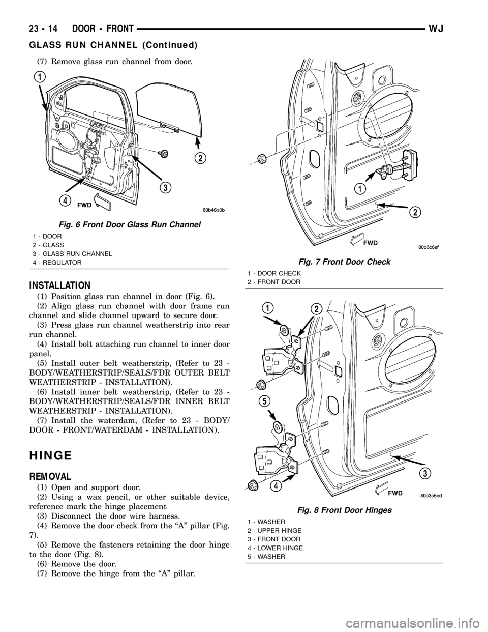
(7) Remove glass run channel from door.
INSTALLATION
(1) Position glass run channel in door (Fig. 6).
(2) Align glass run channel with door frame run
channel and slide channel upward to secure door.
(3) Press glass run channel weatherstrip into rear
run channel.
(4) Install bolt attaching run channel to inner door
panel.
(5) Install outer belt weatherstrip, (Refer to 23 -
BODY/WEATHERSTRIP/SEALS/FDR OUTER BELT
WEATHERSTRIP - INSTALLATION).
(6) Install inner belt weatherstrip, (Refer to 23 -
BODY/WEATHERSTRIP/SEALS/FDR INNER BELT
WEATHERSTRIP - INSTALLATION).
(7) Install the waterdam, (Refer to 23 - BODY/
DOOR - FRONT/WATERDAM - INSTALLATION).
HINGE
REMOVAL
(1) Open and support door.
(2) Using a wax pencil, or other suitable device,
reference mark the hinge placement
(3) Disconnect the door wire harness.
(4) Remove the door check from the ªAº pillar (Fig.
7).
(5) Remove the fasteners retaining the door hinge
to the door (Fig. 8).
(6) Remove the door.
(7) Remove the hinge from the ªAº pillar.
Fig. 6 Front Door Glass Run Channel
1 - DOOR
2 - GLASS
3 - GLASS RUN CHANNEL
4 - REGULATOR
Fig. 7 Front Door Check
1 - DOOR CHECK
2 - FRONT DOOR
Fig. 8 Front Door Hinges
1 - WASHER
2 - UPPER HINGE
3 - FRONT DOOR
4 - LOWER HINGE
5 - WASHER
23 - 14 DOOR - FRONTWJ
GLASS RUN CHANNEL (Continued)
Page 1892 of 2199
DOORS - REAR
TABLE OF CONTENTS
page page
CHECK STRAP
REMOVAL.............................19
INSTALLATION.........................19
DOOR
REMOVAL.............................20
INSTALLATION.........................20
DOOR GLASS
REMOVAL.............................20
INSTALLATION.........................20
EXTERIOR HANDLE
REMOVAL.............................20
INSTALLATION.........................21
HINGE
REMOVAL.............................21
INSTALLATION.........................21
INSIDE HANDLE ACTUATOR
REMOVAL.............................22INSTALLATION.........................22
LATCH
REMOVAL.............................22
INSTALLATION.........................22
LATCH STRIKER
REMOVAL.............................23
INSTALLATION.........................23
TRIM PANEL
REMOVAL.............................23
INSTALLATION.........................23
WATERDAM
REMOVAL.............................23
INSTALLATION.........................24
WINDOW REGULATOR
REMOVAL.............................24
INSTALLATION.........................24
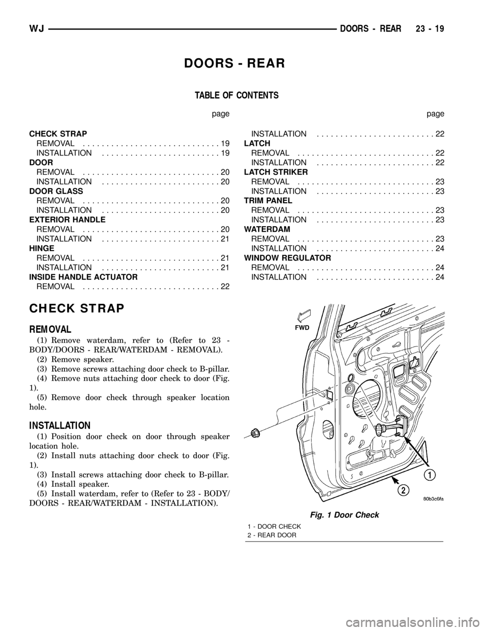
CHECK STRAP
REMOVAL
(1) Remove waterdam, refer to (Refer to 23 -
BODY/DOORS - REAR/WATERDAM - REMOVAL).
(2) Remove speaker.
(3) Remove screws attaching door check to B-pillar.
(4) Remove nuts attaching door check to door (Fig.
1).
(5) Remove door check through speaker location
hole.
INSTALLATION
(1) Position door check on door through speaker
location hole.
(2) Install nuts attaching door check to door (Fig.
1).
(3) Install screws attaching door check to B-pillar.
(4) Install speaker.
(5) Install waterdam, refer to (Refer to 23 - BODY/
DOORS - REAR/WATERDAM - INSTALLATION).
Fig. 1 Door Check
1 - DOOR CHECK
2 - REAR DOOR
WJDOORS - REAR 23 - 19
Page 1893 of 2199
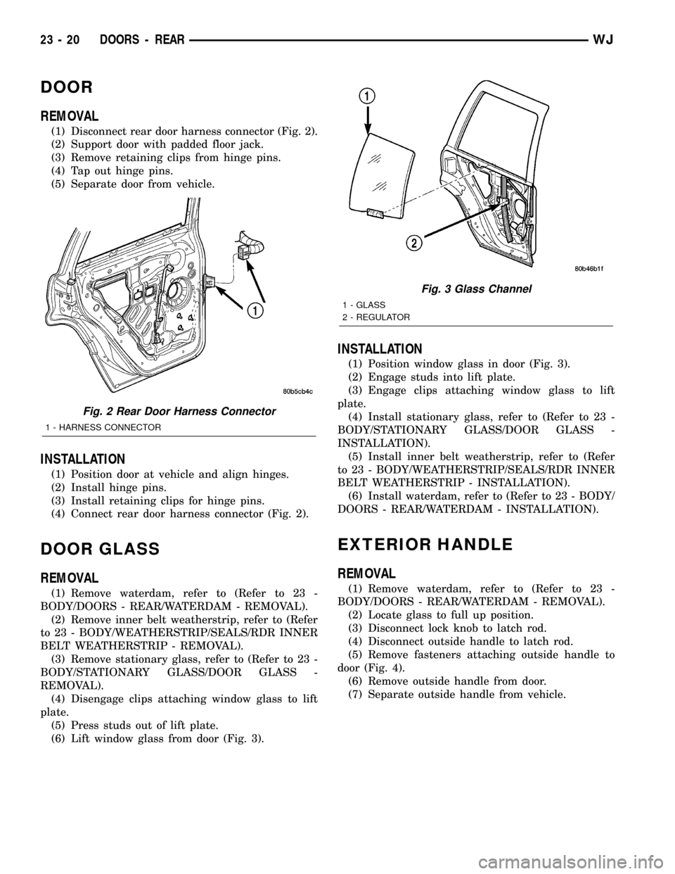
DOOR
REMOVAL
(1) Disconnect rear door harness connector (Fig. 2).
(2) Support door with padded floor jack.
(3) Remove retaining clips from hinge pins.
(4) Tap out hinge pins.
(5) Separate door from vehicle.
INSTALLATION
(1) Position door at vehicle and align hinges.
(2) Install hinge pins.
(3) Install retaining clips for hinge pins.
(4) Connect rear door harness connector (Fig. 2).
DOOR GLASS
REMOVAL
(1) Remove waterdam, refer to (Refer to 23 -
BODY/DOORS - REAR/WATERDAM - REMOVAL).
(2) Remove inner belt weatherstrip, refer to (Refer
to 23 - BODY/WEATHERSTRIP/SEALS/RDR INNER
BELT WEATHERSTRIP - REMOVAL).
(3) Remove stationary glass, refer to (Refer to 23 -
BODY/STATIONARY GLASS/DOOR GLASS -
REMOVAL).
(4) Disengage clips attaching window glass to lift
plate.
(5) Press studs out of lift plate.
(6) Lift window glass from door (Fig. 3).
INSTALLATION
(1) Position window glass in door (Fig. 3).
(2) Engage studs into lift plate.
(3) Engage clips attaching window glass to lift
plate.
(4) Install stationary glass, refer to (Refer to 23 -
BODY/STATIONARY GLASS/DOOR GLASS -
INSTALLATION).
(5) Install inner belt weatherstrip, refer to (Refer
to 23 - BODY/WEATHERSTRIP/SEALS/RDR INNER
BELT WEATHERSTRIP - INSTALLATION).
(6) Install waterdam, refer to (Refer to 23 - BODY/
DOORS - REAR/WATERDAM - INSTALLATION).
EXTERIOR HANDLE
REMOVAL
(1) Remove waterdam, refer to (Refer to 23 -
BODY/DOORS - REAR/WATERDAM - REMOVAL).
(2) Locate glass to full up position.
(3) Disconnect lock knob to latch rod.
(4) Disconnect outside handle to latch rod.
(5) Remove fasteners attaching outside handle to
door (Fig. 4).
(6) Remove outside handle from door.
(7) Separate outside handle from vehicle.
Fig. 2 Rear Door Harness Connector
1 - HARNESS CONNECTOR
Fig. 3 Glass Channel
1 - GLASS
2 - REGULATOR
23 - 20 DOORS - REARWJ
Page 1894 of 2199
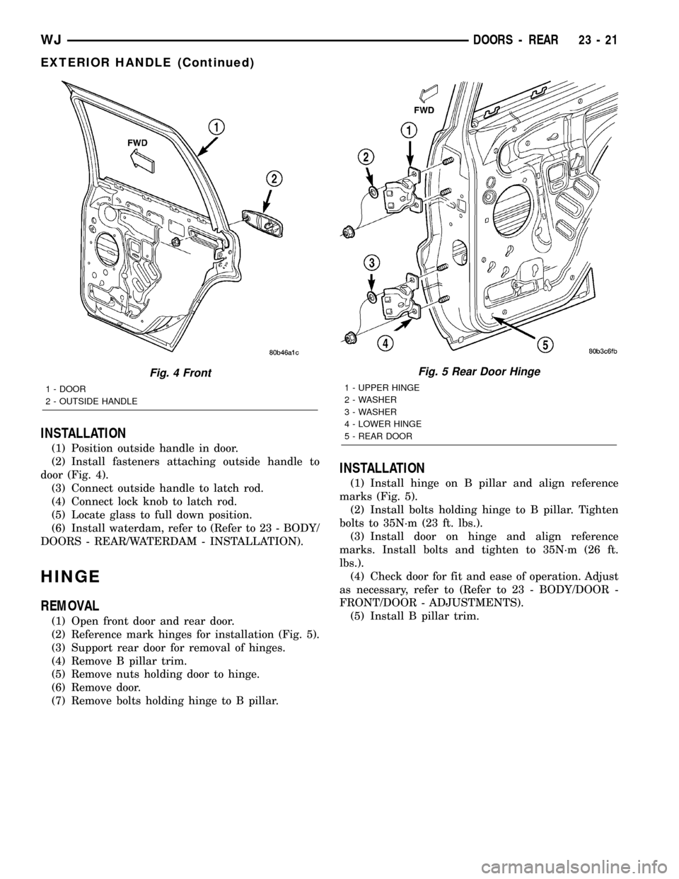
INSTALLATION
(1) Position outside handle in door.
(2) Install fasteners attaching outside handle to
door (Fig. 4).
(3) Connect outside handle to latch rod.
(4) Connect lock knob to latch rod.
(5) Locate glass to full down position.
(6) Install waterdam, refer to (Refer to 23 - BODY/
DOORS - REAR/WATERDAM - INSTALLATION).
HINGE
REMOVAL
(1) Open front door and rear door.
(2) Reference mark hinges for installation (Fig. 5).
(3) Support rear door for removal of hinges.
(4) Remove B pillar trim.
(5) Remove nuts holding door to hinge.
(6) Remove door.
(7) Remove bolts holding hinge to B pillar.
INSTALLATION
(1) Install hinge on B pillar and align reference
marks (Fig. 5).
(2) Install bolts holding hinge to B pillar. Tighten
bolts to 35N´m (23 ft. lbs.).
(3) Install door on hinge and align reference
marks. Install bolts and tighten to 35N´m (26 ft.
lbs.).
(4) Check door for fit and ease of operation. Adjust
as necessary, refer to (Refer to 23 - BODY/DOOR -
FRONT/DOOR - ADJUSTMENTS).
(5) Install B pillar trim.
Fig. 4 Front
1 - DOOR
2 - OUTSIDE HANDLE
Fig. 5 Rear Door Hinge
1 - UPPER HINGE
2 - WASHER
3 - WASHER
4 - LOWER HINGE
5 - REAR DOOR
WJDOORS - REAR 23 - 21
EXTERIOR HANDLE (Continued)